EP0722543B1 - Bremsklotz für scheibenbremsen - Google Patents
Bremsklotz für scheibenbremsen Download PDFInfo
- Publication number
- EP0722543B1 EP0722543B1 EP94925454A EP94925454A EP0722543B1 EP 0722543 B1 EP0722543 B1 EP 0722543B1 EP 94925454 A EP94925454 A EP 94925454A EP 94925454 A EP94925454 A EP 94925454A EP 0722543 B1 EP0722543 B1 EP 0722543B1
- Authority
- EP
- European Patent Office
- Prior art keywords
- brake
- guide
- disc
- brake pad
- brake disc
- Prior art date
- Legal status (The legal status is an assumption and is not a legal conclusion. Google has not performed a legal analysis and makes no representation as to the accuracy of the status listed.)
- Expired - Lifetime
Links
Images

Classifications
-
- F—MECHANICAL ENGINEERING; LIGHTING; HEATING; WEAPONS; BLASTING
- F16—ENGINEERING ELEMENTS AND UNITS; GENERAL MEASURES FOR PRODUCING AND MAINTAINING EFFECTIVE FUNCTIONING OF MACHINES OR INSTALLATIONS; THERMAL INSULATION IN GENERAL
- F16D—COUPLINGS FOR TRANSMITTING ROTATION; CLUTCHES; BRAKES
- F16D65/00—Parts or details
- F16D65/02—Braking members; Mounting thereof
- F16D65/04—Bands, shoes or pads; Pivots or supporting members therefor
- F16D65/092—Bands, shoes or pads; Pivots or supporting members therefor for axially-engaging brakes, e.g. disc brakes
- F16D65/095—Pivots or supporting members therefor
-
- F—MECHANICAL ENGINEERING; LIGHTING; HEATING; WEAPONS; BLASTING
- F16—ENGINEERING ELEMENTS AND UNITS; GENERAL MEASURES FOR PRODUCING AND MAINTAINING EFFECTIVE FUNCTIONING OF MACHINES OR INSTALLATIONS; THERMAL INSULATION IN GENERAL
- F16D—COUPLINGS FOR TRANSMITTING ROTATION; CLUTCHES; BRAKES
- F16D65/00—Parts or details
- F16D65/14—Actuating mechanisms for brakes; Means for initiating operation at a predetermined position
- F16D65/16—Actuating mechanisms for brakes; Means for initiating operation at a predetermined position arranged in or on the brake
- F16D65/18—Actuating mechanisms for brakes; Means for initiating operation at a predetermined position arranged in or on the brake adapted for drawing members together, e.g. for disc brakes
- F16D65/183—Actuating mechanisms for brakes; Means for initiating operation at a predetermined position arranged in or on the brake adapted for drawing members together, e.g. for disc brakes with force-transmitting members arranged side by side acting on a spot type force-applying member
Definitions
- the invention relates to a brake pad for disc brakes according to the preamble of claim 1 and a Floating caliper disc brake with an inventive Brake pad.
- a generic brake pad is from DE 78 03 310 U1 known.
- This known brake pad has two on the side protruding hammer head-shaped guide parts on which the Brake pad is supported and guided.
- the associated Floating caliper disc brake has a brake carrier with Support arms protruding over the edge of a brake disc.
- the Support arms are with guide surfaces for the contact parts the brake pads.
- the brake pads are pulling both on the brake disc inlet side as also supported on the brake disc outlet side.
- the guide surfaces for the pulling support are radial arranged inside the brake disc edge. For this This guide surfaces can be on each axial side just stretch it close to the brake disc and it is not possible one from the inner to the outer Continuous guide surface on the axial side for both brake pads to provide. But there is a risk that the Back plates of worn brake pads in the axial direction slide towards the brake disc from the guide surfaces and in extreme cases the brake pad will fall out could.
- the object of the invention is to provide a brake pad for disc brakes to be specified, even if the friction lining is worn is secured against radial falling out and yet is inexpensive to manufacture.
- the brake pad by means of inner radial support surfaces in Direction supported radially on the wheel axis.
- inner radial support surfaces in Direction supported radially on the wheel axis.
- vertical anchoring surface arranged in a sharp edge
- arcuate bulge provided through which the occurring mechanical stresses can be significantly reduced and the risk of breakage is averted.
- Radial support surfaces can also according to claim 5 the locking lugs themselves are provided so that the inner radial support surfaces are eliminated according to claim 3 and replaced by an enlarged arcuate bulge can be.
- the locking lugs according to the invention are optimally dimensioned, if according to claim 7 by one of the thickness of the Project the corresponding amount from the back plate.
- the back plates of an inventive Brake pads are advantageously thin, since yes no longer the thickness of the back plate to secure against radial fall out serves.
- Claims 9 to 13 relate to a floating caliper disc brake, the brake pads according to the invention provided and by advantageous measures for use this brake pads is particularly suitable.
- the described Features can be used particularly advantageously with conventional floating caliper disc brakes, adapted to the use of brake pads according to the invention should be.
- the support arms are provided with recesses into which the locking lugs can intervene. It is not necessary that the Lugs according to claim 13 bear against the support arms. Rather, it is advantageous according to claim 10 Normally, locking lugs do not rest on the support arms allow.
- the recesses of the support arms can be in in this case, simply when casting without additional manufacturing costs be molded on.
- the cast surface must not be processed here costly since it is is not a management area. Only in an emergency if the brake pad slips off the actual guide surface, prevent the locking lugs by contacting one Radially falling out of the area of the recess Brake pads.
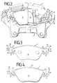
- a floating caliper disc brake can be seen in FIGS. 1 and 2 with brake pads 1,2 according to the invention are arranged on both sides of a brake disc 3.
- a Floating saddle 4 encompasses the one indicated by dashed lines Brake disc edge 5 and the brake pads 1,2 to this press the brake disc 3.
- the floating saddle 4 is by means of two bolt guides 6, 7 on a brake carrier 8 axially displaceable.
- the brake carrier 8 has two support arms 9, 10 projecting beyond the brake disc edge, the adjacent to both axial sides of the brake disc 3 and in Secant direction 11 pairs of opposite guide surfaces 12, 13, 14, 15, 16, 17 for guiding and supporting the Have brake pads 1.2.
- FIG. 1 has an inventive brake lining 1, 2 a back plate 20, on which a friction lining 21 is attached.
- a back plate 20 From the back plate 20 are laterally in opposite secant directions 11 two guide parts 22, 23, each one radial have anchored anchoring section 24, and provided on their narrow sides with support surfaces 25, 26, 27 are.
- the two are in the secant direction 11 outwardly facing end faces 25 of the guide parts 22,23 on the first guide surfaces 12,13 and the inwardly facing anchor surfaces 26 on the second Guide surfaces 14, 15 of the support arms 9, 10.
- the inner ones radial support surfaces 27 rest in the radial direction the third guide surfaces 16, 17 on the hook-shaped Sections 18, 19 of the support arms 9, 10 are formed are.
- the brake pads 1,2 When braking, the brake pads 1,2 from the frictional force taken in the circumferential direction of the brake disc 3, wherein those on the outlet side of the brake disc 3 End faces 25 against the first guide surfaces 12 and 13 be pressed.
- the brake pad 1,2 is supported pressing on those located in the outlet of the brake disc 3 Guide part 22.23.
- the other two guide parts 22.23, which is on the other side in the inlet of the brake disc 3 are located with their anchor surfaces 26 the second guide surfaces 14, 15, the respective one Brake pad 1 or 2 is supported pulling.
- the first guide surfaces are to prevent torques 12, 13 of the support arms 9, 10 and the end faces 25 of the guide parts 22, 23 radially outside the brake disc edge 5 arranged.
- the second guide surfaces are for the same reason 14, 15 of the support arms 9, 10 and the associated anchor surfaces 26 of the guide parts 22, 23 radially inside the Brake disc edge 5 arranged.
- the third guide surfaces 16, 17 of the support arms 9, 10 for supporting the inner radial Support surfaces 27 of the brake pads 1, 2 are arranged.
- the first guide surfaces 12, 13 can due to their location just as well designed as a continuous guide surface 12, 13 will. This is the second guide area 14, 15 and the third guide surfaces 16, 17 are not possible, since they cannot penetrate the brake disc 3. Much more the second guide surfaces 14, 15 and the third Guide surfaces 16, 17 in the axial direction shortly before reaching the brake disc 3 ends, so that a slight axial Clearance 28, 29 for the movement of the brake disc 3 remains.
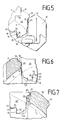
- Recess 31 provided in Figures 2, 5 and 6th is designed as a bevel 32.
- the recesses 31 or bevels 32 run from the inner axial side over the brake disc edge 5 to the outer axial side almost over the entire axial length of the support arms 9, 10 and extend into the area of the axially inner first guide surfaces 13 as well as in the area of the axially outer first guide surfaces 12.
- the locking lugs 30 grip although in the recesses 31,32, but touch in normal operation not the support arms 9.10. Only if the If the emergency described above occurs, the safety lugs are supported 30 on the support arms 9,10 and prevent one Brake pads 1,2 fall out of the brake.
- the support arms 9, 10 are provided with a bevel 32 are recommended, the one shown in most figures oblique arrangement of the locking lugs 30 on the outer Corners of the guide parts 22, 23.
- the one shown in Figure 7 Embodiment protrude the slightly modified locking lugs 30 'only in the secant direction 11 over the End faces 25 of the modified guide parts 23 '.
- the modified support arm 10 ' is reinforced with a rib 33, around the material removed in the recess 31 again add and the strength of the original cross section to restore.
- the locking lugs 30 make a large one Thickness of the back plates 20 to secure against radial Falling out unnecessarily, so that the back plates 20 a have low thickness for their manufacturing costs can.
- the guide parts 22,23 In order to tear the guide parts under heavy loads 22, 23 on the cutting edge of the anchor surfaces 26 and to avoid the inner radial support surfaces 27, are the guide parts 22,23 at this point with an arcuate bulge 34.
- the floating caliper 4 is supported on its axial outside on the outer brake pad 2.
- the guide parts 22 of the brake pad 2 additionally with outer radial contact surfaces 35 for supporting the floating saddle 4 provided.
Landscapes
- Engineering & Computer Science (AREA)
- General Engineering & Computer Science (AREA)
- Mechanical Engineering (AREA)
- Braking Arrangements (AREA)
Description
- Figur 1:
- eine Draufsicht auf eine Teilbelag-Scheibenbremse mit erfindungsgemäßen Bremsbelägen,
- Figur 2 :
- eine teilweise geschnittene Seitenansicht einer Teilbelag-Scheibenbremse mit erfindungsgemäßen Bremsbelägen,
- Figur 3 :
- eine Draufsicht auf die Rückseite eines Bremsbelags, der zur Verwendung auf der äußeren Axialseite der Scheibenbremse von Figur 2 bestimmt ist,
- Figur 4 :
- eine Draufsicht auf die Vorderseite eines Bremsbelags, der zur Verwendung auf der inneren Axialseite der Bremse von Figur 2 bestimmt ist,
- Figur 5 :
- einen vergrößerten Ausschnitt der rechten Seite von Figur 2,
- Figur 6 :
- einen vergrößerten Ausschnitt der linken Seite von Figur 2,
- Figur 7:
- einen Ausschnitt einer anderen Scheibenbremse mit einer weiteren Ausführungsform eines erfindungsgemäßen Bremsbelags.
Claims (13)
- Bremsbelag für Scheibenbremsen, mit einer Rückenplatte (20), die einen Reibbelag (21) trägt und seitlich in zwei bezüglich einer Bremsscheibe (3) in entgegengesetzte Sekantenrichtungen (11) abstehende, reibbelagfreie Führungsteile (22,23) übergeht, die jeweils einen radial nach innen abgewinkelten Ankerabschnitt (24) aufweisen und an ihren Schmalseiten mit Abstützflächen (25,26,27) versehen sind, wobei in Sekantenrichtung (11) nach außen gewandte Stirnflächen (25) der Führungsteile (22,23) radial außerhalb des Bremsscheibenrandes (5) und zu den Stirnflächen (25) parallele, aber nach innen gewandte Ankerflächen (26) der Ankerabschnitte (24) radial innerhalb des Bremsscheibenrandes (5) angeordnet sind, so daß der Bremsbelag (1,2) über das auf der Einlaufseite der Bremsscheibe (3) befindliche Führungsteil (22,23) ziehend und über das andere Führungsteil (22,23) drückend abgestützt werden kann, dadurch gekennzeichnet, daß die Führungsteile (22,23) jeweils eine zusätzliche Sicherungsnase (30) aufweisen, die radial außerhalb des Bremsscheibenrandes (5) angeordnet ist und in Sekantenrichtung (11) über die Stirnflächen (25) hinausragt.
- Bremsbelag nach Anspruch 1, dadurch gekennzeichnet, daß die Sicherungsnasen (30) an den äußeren Ecken der Führungsteile (22,23) schräg angeordnet sind und auch in radialer Richtung abstehen.
- Bremsbelag nach Anspruch 1 oder 2, dadurch gekennzeichnet, daß eine radial innerhalb des Bremsscheibenrandes (5) angeordnete, der Bremsscheibenachse zugewandte Schmalseite der Führungsteile (22,23) eine innere radiale Abstützfläche (27) aufweist, die neben dem Ankerabschnitt (24) senkrecht zur Ankerfläche (26) angeordnet ist.
- Bremsbelag nach Anspruch 3, dadurch gekennzeichnet, daß die radiale Abstützfläche (27) über eine bogenförmige Ausbuchtung (34) in die Ankerfläche (26) übergeht.
- Bremsbelag nach Anspruch 1, dadurch gekennzeichnet, daß eine radiale Abstützfläche an der Sicherungsnase (30) vorgesehen ist.
- Bremsbelag nach einem der Ansprüche 1 bis 5, dadurch gekennzeichnet, daß eine radial außerhalb des Bremsscheibenrandes (5) angeordnete Schmalseite der Führungsteile (22) eine äußere radiale Auflagefläche (35) für die Auflage eines Schwimmsattels (4) einer Schwimmsattel-Scheibenbremse aufweist.
- Bremsbelag nach einem der Ansprüche 1 bis 6, dadurch gekennzeichnet, daß die Abmessungen der Sicherungsnasen (30) im wesentlichen der Dicke der Rückenplatten (20) entsprechen.
- Bremsbelag nach Anspruch 7, dadurch gekennzeichnet, daß die Dicke der Rückenplatte (20) höchsten 4 mm beträgt.
- Schwimmsattel-Scheibenbremse mit Bremsbelägen nach einem der Ansprüche 1 bis 8, mit einem den Bremsscheibenrand (5) und die Bremsbeläge (1,2) umgreifenden Schwimmsattel (4), der an einem Bremsträger (8) axial verschiebbar gelagert ist, mit zwei über den Bremsscheibenrand (5) ragenden Trägerarmen (9,10) des Bremsträgers (8), die zu beiden Axialseiten der Bremsscheibe (3) benachbarte Führungsflächen (12,13,14,15,16,17) zur Führung und Abstützung der Bremsbeläge (1,2) aufweisen, wobei jeweils paarweise gegenüberliegende, der Bremsenmitte zugewandte erste Führungsflächen (12,13) der Trägerarme (9,10) zur Anlage der Stirnflächen (25) und radial innerhalb des Bremsscheibenrandes (5) an hakenförmigen Abschnitten (18,19) der Trägerarme (9,10) angeordnete zweite Führungsflächen (14,15) zur Anlage der Ankerflächen (26) sowie dritte Führungsflächen (16,17) zur Anlage der inneren radialen Abstützflächen (27) der Führungsteile (22,23) vorgesehen sind, dadurch gekennzeichnet, daß die Trägerarme (9,10) je eine axial verlaufende, den ersten Führungsflächen (12,13) benachbarte Ausnehmung (31) aufweisen, die sich über den Bremsscheibenrand (5) beiderseits bis in den Bereich der Bremsbeläge (1,2) erstreckt, und daß die Sicherungsnasen (30) in die Ausnehmungen (31) eingreifen.
- Scheibenbremse nach Anspruch 9, dadurch gekennzeichnet, daß die Sicherungsnasen (30) die Trägerarme (9,10) nur im Notfall berühren, wenn die inneren radialen Abstützflächen (27) der Führungsteile (22,23) des Bremsbelags (1,2) von den dritten Führungsflächen (16,17) der hakenförmigen Abschnitte (18,19) der Trägerarme (9,10) abrutschen.
- Scheibenbremse nach Anspruch 9 oder 10, dadurch gekennzeichnet, daß der aufgrund der Ausnehmungen (31) geschwächte Querschnitt der Trägerarme (9,10) durch Zufügen von Material auf der Außenseite der Trägerarme (9,10) in Form von Rippen (33) verstärkt wird.
- Scheibenbremse nach einem der Ansprüche 9 bis 11, dadurch gekennzeichnet, daß die Ausnehmung (31) als einfache Abschrägung (32) ausgebildet ist.
- Scheibenbremse nach Anspruch 9, dadurch gekennzeichnet, daß die Sicherungsnasen (30) mit radialen Abstützflächen versehen sind, die im Bereich der Ausnehmungen (31) auf den Trägerarmen (9,10) radial aufliegen.
Applications Claiming Priority (3)
| Application Number | Priority Date | Filing Date | Title |
|---|---|---|---|
| DE4334840A DE4334840A1 (de) | 1993-10-13 | 1993-10-13 | Bremsbelag für Scheibenbremsen |
| DE4334840 | 1993-10-13 | ||
| PCT/EP1994/002693 WO1995010713A1 (de) | 1993-10-13 | 1994-08-12 | Bremsklotz für scheibenbremsen |
Publications (2)
| Publication Number | Publication Date |
|---|---|
| EP0722543A1 EP0722543A1 (de) | 1996-07-24 |
| EP0722543B1 true EP0722543B1 (de) | 1998-01-07 |
Family
ID=6500016
Family Applications (1)
| Application Number | Title | Priority Date | Filing Date |
|---|---|---|---|
| EP94925454A Expired - Lifetime EP0722543B1 (de) | 1993-10-13 | 1994-08-12 | Bremsklotz für scheibenbremsen |
Country Status (11)
| Country | Link |
|---|---|
| EP (1) | EP0722543B1 (de) |
| JP (1) | JPH09509238A (de) |
| KR (1) | KR960705152A (de) |
| CN (1) | CN1071433C (de) |
| CZ (1) | CZ77196A3 (de) |
| DE (2) | DE4334840A1 (de) |
| ES (1) | ES2114700T3 (de) |
| HU (1) | HU214729B (de) |
| PL (1) | PL313940A1 (de) |
| SK (1) | SK34396A3 (de) |
| WO (1) | WO1995010713A1 (de) |
Families Citing this family (16)
| Publication number | Priority date | Publication date | Assignee | Title |
|---|---|---|---|---|
| DE19652936A1 (de) * | 1996-12-02 | 1998-06-04 | Teves Gmbh Alfred | Teilbelag-Scheibenbremse |
| DE19719640A1 (de) * | 1997-05-09 | 1998-11-12 | Itt Mfg Enterprises Inc | Bremsbackenhalterung für eine Teilbelagscheibenbremse |
| EP1499814B2 (de) † | 2002-07-15 | 2013-12-11 | Freni Brembo S.p.A. | Bremsbelag für scheibenbremse |
| DE10257353A1 (de) * | 2002-12-05 | 2004-06-17 | Goldbach Automobile Consulting Gmbh | Scheibenbremse mit Belagträger |
| DE10312478B4 (de) * | 2003-03-20 | 2007-03-29 | Lucas Automotive Gmbh | Scheibenbremse |
| DE10312479B4 (de) * | 2003-03-20 | 2007-05-03 | Lucas Automotive Gmbh | Scheibenbremse |
| GB201016013D0 (en) * | 2010-09-24 | 2010-11-10 | Meritor Heavy Vehicle Braking | Brake assembly |
| DE102011118314B4 (de) * | 2011-11-11 | 2013-09-26 | Wabco Radbremsen Gmbh | Scheibenbremse, insbesondere für nutzfahrzeuge, sowie bremsbelag und druckplatte als separate bauteile für eine solche scheibenbremse |
| KR20150083850A (ko) * | 2012-11-13 | 2015-07-20 | 스미또모 베이크라이트 가부시키가이샤 | 브레이크 패드 및 캘리퍼 장치 |
| CN104279252A (zh) * | 2013-07-04 | 2015-01-14 | 上海大陆汽车制动系统销售有限公司 | 推拉结构的盘式制动器 |
| DE102013012547B4 (de) * | 2013-07-29 | 2021-08-19 | Wabco Europe Bvba | Scheibenbremse, insbesondere für Nutzfahrzeuge, sowie Bremsbelag einer solchen Scheibenbremse |
| PL3265689T3 (pl) * | 2015-03-04 | 2021-10-25 | Brembo S.P.A. | Wielowarstwowy klocek do hamulca tarczowego |
| DE102016209069A1 (de) | 2015-08-31 | 2017-03-02 | Continental Teves Ag & Co. Ohg | Rückenplatte für einen Scheibenbremsbelag, Scheibenbremsbelag und Festsattelscheibenbremse dazu |
| DE102016104967A1 (de) * | 2015-10-09 | 2017-04-13 | Knorr-Bremse Systeme für Nutzfahrzeuge GmbH | Bremsträger |
| DK3791085T3 (da) * | 2018-05-09 | 2022-05-30 | Continental Teves Ag & Co Ohg | Omdrejningsafhængigt konfektioneret skivebremsebelægning til en skivebremse med fast beslag |
| EP3584462B1 (de) * | 2018-06-20 | 2020-05-20 | WABCO Europe BVBA | Belagträger für eine scheibenbremse |
Family Cites Families (10)
| Publication number | Priority date | Publication date | Assignee | Title |
|---|---|---|---|---|
| JPS52135969A (en) * | 1976-05-11 | 1977-11-14 | Akebono Brake Ind Co Ltd | Friction pad of disc brake |
| DE7803310U1 (de) * | 1978-02-04 | 1981-06-11 | Alfred Teves Gmbh, 6000 Frankfurt | Bremsbacke fuer eine teilbelagscheibenbremse, insbesondere fuer kraftfahrzeuge |
| US4220223A (en) * | 1978-08-01 | 1980-09-02 | Kelsey Hayes Co. | Sliding caliper disc brake friction pad assemblies |
| DE2926818A1 (de) * | 1979-07-03 | 1981-03-12 | Alfred Teves Gmbh, 6000 Frankfurt | Teilbelagscheibenbremse. |
| US4548300A (en) * | 1983-08-31 | 1985-10-22 | Rockwell International Corporation | Disc brake friction pad and stabilizing support |
| FR2606107B1 (fr) * | 1986-10-31 | 1988-12-02 | Bendix France | Plaquette pour frein a disque et frein a disque equipe de telles plaquettes |
| DE3827686A1 (de) * | 1988-08-16 | 1990-02-22 | Teves Gmbh Alfred | Bremsbacke |
| DE3910969C2 (de) * | 1989-04-05 | 1994-09-01 | Teves Gmbh Alfred | Teilbelag-Scheibenbremse |
| DE3816109A1 (de) * | 1988-05-11 | 1989-11-23 | Teves Gmbh Alfred | Scheibenbremse mit unverwechselbaren bremskloetzen |
| DE4002863A1 (de) * | 1990-02-01 | 1991-08-08 | Teves Gmbh Alfred | Bremsklotz |
-
1993
- 1993-10-13 DE DE4334840A patent/DE4334840A1/de not_active Withdrawn
-
1994
- 1994-08-12 DE DE59404978T patent/DE59404978D1/de not_active Expired - Lifetime
- 1994-08-12 KR KR1019960701396A patent/KR960705152A/ko not_active Abandoned
- 1994-08-12 SK SK343-96A patent/SK34396A3/sk unknown
- 1994-08-12 CZ CZ96771A patent/CZ77196A3/cs unknown
- 1994-08-12 ES ES94925454T patent/ES2114700T3/es not_active Expired - Lifetime
- 1994-08-12 JP JP7511217A patent/JPH09509238A/ja active Pending
- 1994-08-12 PL PL94313940A patent/PL313940A1/xx unknown
- 1994-08-12 EP EP94925454A patent/EP0722543B1/de not_active Expired - Lifetime
- 1994-08-12 HU HU9600966A patent/HU214729B/hu not_active IP Right Cessation
- 1994-08-12 CN CN94193736A patent/CN1071433C/zh not_active Expired - Fee Related
- 1994-08-12 WO PCT/EP1994/002693 patent/WO1995010713A1/de not_active Ceased
Also Published As
| Publication number | Publication date |
|---|---|
| HU9600966D0 (en) | 1996-06-28 |
| WO1995010713A1 (de) | 1995-04-20 |
| HU214729B (hu) | 1998-05-28 |
| SK34396A3 (en) | 1996-10-02 |
| EP0722543A1 (de) | 1996-07-24 |
| ES2114700T3 (es) | 1998-06-01 |
| CN1071433C (zh) | 2001-09-19 |
| CN1133082A (zh) | 1996-10-09 |
| PL313940A1 (en) | 1996-08-05 |
| DE59404978D1 (de) | 1998-02-12 |
| KR960705152A (ko) | 1996-10-09 |
| CZ77196A3 (en) | 1996-09-11 |
| HUT74218A (en) | 1996-11-28 |
| JPH09509238A (ja) | 1997-09-16 |
| DE4334840A1 (de) | 1995-04-20 |
Similar Documents
| Publication | Publication Date | Title |
|---|---|---|
| EP0722543B1 (de) | Bremsklotz für scheibenbremsen | |
| DE2919537C2 (de) | Bremsbelag für eine Kraftfahrzeug-Scheibenbremse | |
| DE2804808C3 (de) | Bremsbackenhalterung für eine Teilbelagscheibenbremse, insbesondere für Kraftfahrzeuge | |
| DE3919179C2 (de) | ||
| DE69701946T2 (de) | Reibscheibe mit aus Segmenten bestehenden Belägen | |
| EP2252805B1 (de) | Scheibenbremse mit orientierungsgesichertem einbau der bremsbeläge | |
| DE8615015U1 (de) | Blattfeder zum Niederhalten der Belag-Tragplatte einer Scheibenbremse | |
| DE3540810C1 (de) | Schwimmsattel-Scheibenbremse | |
| DE1450130B2 (de) | ||
| EP1898115A1 (de) | Fahrzeug-Scheibenbremse | |
| EP2761200A1 (de) | Scheibenbremse, insbesondere für ein nutzfahrzeug, sowie bremsbelag für eine scheibenbremse | |
| DE2904118A1 (de) | Teilbelagscheibenbremse, insbesondere fuer kraftfahrzeuge | |
| DE2501874A1 (de) | Segmentierte bremsscheibe | |
| DE3410127C2 (de) | Einstückige Bremsscheibe | |
| DE2447555C3 (de) | Kohlenstoff-Bremsscheibe für Mehrscheienbremsen | |
| DE8519567U1 (de) | Scheibenbremse mit Bremssattel und durch Haken im Bremssattel befestigten Bremsbelägen | |
| DE4110869C2 (de) | Festsattel-Teilbelagscheibenbremse | |
| DE2718003A1 (de) | Scheibenbremse fuer fahrzeuge, insbesondere strassenfahrzeuge | |
| DE69514482T2 (de) | Scheibenbremse | |
| WO1992017713A1 (de) | Festsattel-teilbelagscheibenbremse | |
| DE7901527U1 (de) | Scheibenbremse | |
| EP0760061B1 (de) | Zuspannvorrichtung für eine scheibenbremse | |
| DE3014057A1 (de) | Bremsbackenhalterung fuer eine teilbelagscheibenbremse, insbesondere fuer kraftfahrzeuge | |
| WO1993003289A1 (de) | Schwimmrahmen-scheibenbremse mit komfortabler bremsbackenanordnung | |
| DE69004024T2 (de) | Bremsbacke für Trommelbremsen. |
Legal Events
| Date | Code | Title | Description |
|---|---|---|---|
| PUAI | Public reference made under article 153(3) epc to a published international application that has entered the european phase |
Free format text: ORIGINAL CODE: 0009012 |
|
| 17P | Request for examination filed |
Effective date: 19960513 |
|
| AK | Designated contracting states |
Kind code of ref document: A1 Designated state(s): DE ES FR GB IT |
|
| GRAG | Despatch of communication of intention to grant |
Free format text: ORIGINAL CODE: EPIDOS AGRA |
|
| 17Q | First examination report despatched |
Effective date: 19961216 |
|
| ITF | It: translation for a ep patent filed | ||
| GRAG | Despatch of communication of intention to grant |
Free format text: ORIGINAL CODE: EPIDOS AGRA |
|
| GRAH | Despatch of communication of intention to grant a patent |
Free format text: ORIGINAL CODE: EPIDOS IGRA |
|
| GRAH | Despatch of communication of intention to grant a patent |
Free format text: ORIGINAL CODE: EPIDOS IGRA |
|
| GRAA | (expected) grant |
Free format text: ORIGINAL CODE: 0009210 |
|
| AK | Designated contracting states |
Kind code of ref document: B1 Designated state(s): DE ES FR GB IT |
|
| REF | Corresponds to: |
Ref document number: 59404978 Country of ref document: DE Date of ref document: 19980212 |
|
| ET | Fr: translation filed | ||
| GBT | Gb: translation of ep patent filed (gb section 77(6)(a)/1977) |
Effective date: 19980320 |
|
| REG | Reference to a national code |
Ref country code: ES Ref legal event code: FG2A Ref document number: 2114700 Country of ref document: ES Kind code of ref document: T3 |
|
| PLBE | No opposition filed within time limit |
Free format text: ORIGINAL CODE: 0009261 |
|
| STAA | Information on the status of an ep patent application or granted ep patent |
Free format text: STATUS: NO OPPOSITION FILED WITHIN TIME LIMIT |
|
| 26N | No opposition filed | ||
| PGFP | Annual fee paid to national office [announced via postgrant information from national office to epo] |
Ref country code: GB Payment date: 20010725 Year of fee payment: 8 |
|
| PGFP | Annual fee paid to national office [announced via postgrant information from national office to epo] |
Ref country code: ES Payment date: 20010809 Year of fee payment: 8 |
|
| PGFP | Annual fee paid to national office [announced via postgrant information from national office to epo] |
Ref country code: FR Payment date: 20010820 Year of fee payment: 8 |
|
| REG | Reference to a national code |
Ref country code: GB Ref legal event code: IF02 |
|
| PG25 | Lapsed in a contracting state [announced via postgrant information from national office to epo] |
Ref country code: GB Free format text: LAPSE BECAUSE OF NON-PAYMENT OF DUE FEES Effective date: 20020812 |
|
| PG25 | Lapsed in a contracting state [announced via postgrant information from national office to epo] |
Ref country code: ES Free format text: LAPSE BECAUSE OF NON-PAYMENT OF DUE FEES Effective date: 20020813 |
|
| GBPC | Gb: european patent ceased through non-payment of renewal fee |
Effective date: 20020812 |
|
| PG25 | Lapsed in a contracting state [announced via postgrant information from national office to epo] |
Ref country code: FR Free format text: LAPSE BECAUSE OF NON-PAYMENT OF DUE FEES Effective date: 20030430 |
|
| REG | Reference to a national code |
Ref country code: FR Ref legal event code: ST |
|
| REG | Reference to a national code |
Ref country code: ES Ref legal event code: FD2A Effective date: 20030912 |
|
| PG25 | Lapsed in a contracting state [announced via postgrant information from national office to epo] |
Ref country code: IT Free format text: LAPSE BECAUSE OF NON-PAYMENT OF DUE FEES;WARNING: LAPSES OF ITALIAN PATENTS WITH EFFECTIVE DATE BEFORE 2007 MAY HAVE OCCURRED AT ANY TIME BEFORE 2007. THE CORRECT EFFECTIVE DATE MAY BE DIFFERENT FROM THE ONE RECORDED. Effective date: 20050812 |
|
| PGFP | Annual fee paid to national office [announced via postgrant information from national office to epo] |
Ref country code: DE Payment date: 20120831 Year of fee payment: 19 |
|
| PG25 | Lapsed in a contracting state [announced via postgrant information from national office to epo] |
Ref country code: DE Free format text: LAPSE BECAUSE OF NON-PAYMENT OF DUE FEES Effective date: 20140301 |
|
| REG | Reference to a national code |
Ref country code: DE Ref legal event code: R119 Ref document number: 59404978 Country of ref document: DE Effective date: 20140301 |