EP0722026A2 - Dispositif pour la fixation d'un élément de construction en forme de plaque sur un mur ou similaire - Google Patents
Dispositif pour la fixation d'un élément de construction en forme de plaque sur un mur ou similaire Download PDFInfo
- Publication number
- EP0722026A2 EP0722026A2 EP96100427A EP96100427A EP0722026A2 EP 0722026 A2 EP0722026 A2 EP 0722026A2 EP 96100427 A EP96100427 A EP 96100427A EP 96100427 A EP96100427 A EP 96100427A EP 0722026 A2 EP0722026 A2 EP 0722026A2
- Authority
- EP
- European Patent Office
- Prior art keywords
- mounting
- wall
- support
- component
- handrail
- Prior art date
- Legal status (The legal status is an assumption and is not a legal conclusion. Google has not performed a legal analysis and makes no representation as to the accuracy of the status listed.)
- Granted
Links
- 125000006850 spacer group Chemical group 0.000 claims description 16
- 230000004323 axial length Effects 0.000 claims description 2
- 239000002184 metal Substances 0.000 description 17
- 229910052751 metal Inorganic materials 0.000 description 17
- 238000004519 manufacturing process Methods 0.000 description 3
- XEEYBQQBJWHFJM-UHFFFAOYSA-N Iron Chemical compound [Fe] XEEYBQQBJWHFJM-UHFFFAOYSA-N 0.000 description 2
- 238000007373 indentation Methods 0.000 description 2
- 239000007787 solid Substances 0.000 description 2
- 238000005452 bending Methods 0.000 description 1
- 230000006835 compression Effects 0.000 description 1
- 238000007906 compression Methods 0.000 description 1
- 238000010276 construction Methods 0.000 description 1
- 230000000694 effects Effects 0.000 description 1
- 239000013013 elastic material Substances 0.000 description 1
- 229910052742 iron Inorganic materials 0.000 description 1
- 230000003287 optical effect Effects 0.000 description 1
- 230000002093 peripheral effect Effects 0.000 description 1
- 230000000284 resting effect Effects 0.000 description 1
- 238000010079 rubber tapping Methods 0.000 description 1
Images


Classifications
-
- E—FIXED CONSTRUCTIONS
- E04—BUILDING
- E04F—FINISHING WORK ON BUILDINGS, e.g. STAIRS, FLOORS
- E04F11/00—Stairways, ramps, or like structures; Balustrades; Handrails
- E04F11/18—Balustrades; Handrails
- E04F11/181—Balustrades
- E04F11/1812—Details of anchoring to the wall or floor
-
- E—FIXED CONSTRUCTIONS
- E04—BUILDING
- E04F—FINISHING WORK ON BUILDINGS, e.g. STAIRS, FLOORS
- E04F19/00—Other details of constructional parts for finishing work on buildings
- E04F19/02—Borders; Finishing strips, e.g. beadings; Light coves
- E04F19/026—Borders; Finishing strips, e.g. beadings; Light coves specially adapted for cushioning impacts
Definitions
- the invention relates to a device of the type specified in the preamble of claim 1.
- the supports consist of bases to be fastened to the wall or the like, with which support parts in the form of sliding blocks are connected, which are formed in correspondingly shaped, on the rear sides of the plate-shaped components Grooves are used.
- the invention is therefore based on the object to design the generic device so that regardless of whether it is used only as a support for the handrail or as a support for the component, a pleasing appearance can be given and the handrail assembled in sections and can be dismantled.
- the invention has the essential advantage that the support can either be used together with a simple top cap as a carrier for a handrail or together with a mounting plate provided instead of the top cap as a carrier for both the handrail and for the plate-shaped component.
- the appearance of the support is essentially determined by the largely arbitrarily designed upper part.
- the various handrail sections can be easily assembled or disassembled because they only need to be placed on the support surface, but do not need to be laterally pulled onto a pipe section or the like.
- the handrail element 1 shows an inventive handrail element 1 in the form of a tubular element which has a longitudinal axis 2.
- the handrail element 1 contains a hollow cylindrical metal tube 3 and a plastic sheathing 4 mounted thereon, which preferably also consists of a tube and has the same length as the metal tube 3.
- a connecting element 5 is inserted into each of the two open ends of the metal tube 3 serving as receiving openings.
- the handrail element 1 could also consist of a solid rod, the ends of which have end-side receiving openings for the connection elements 5.
- Each connecting element 5 contains a cylindrical fastening section 6 inserted into the pipe end with an outer diameter corresponding to the inner diameter of the metal pipe 3 and one on the fastening section 6 along a circumferential shoulder 7 connected mounting section 8.
- the shoulder 7 has a height corresponding approximately to the wall thickness of the metal tube 3, so that the largest outside diameter of the mounting section 8 corresponds at most to the outside diameter of the metal tube 3.
- the fastening section 6 is inserted into the metal tube 3 in such a way that the shoulder 7 rests against its front end face, and for example by means of indentations 9, which are formed in the metal tube 3 and protrude into a transverse bore 10 of the fastening section 6, in the direction of the longitudinal axis 2 immovably and fixed non-rotatably in the metal tube 3.
- the mounting section 8 is essentially semi-cylindrical at its front end 11 so that it can form an assembly block together with a correspondingly designed front end 12 (FIG.
- the front ends 11 and 12 each have in their flat, mutually facing sections a recess 16 (FIG. 1) and an extension 17 projecting beyond the longitudinal axis (2), as a result of which the front ends 11, 12 are given a hook-like shape .
- the mounting sections 8, 14 each have a continuous transverse bore 18 for receiving a fastening screw 19 (FIG. 2).
- a handrail element 20 which has a tubular, plastic arch element 21, in which a metal insert 22 is arranged, which is somewhat shorter than the handrail element 20 and has a threaded bore 23 at at least one end, into which a threaded bolt 24 is screwed, which is provided at one end of a cylindrical insert 25 with an outer diameter corresponding to the outer diameter of the fastening section 6.
- the threaded bolt 24 can be secured against rotation by a transverse pin which projects into the threaded bolt 24 and the wall of the arch element 21 and the insert 22 Cross hole is inserted.
- the insert 25 is stuck in a receiving opening at one end of a tube piece 28 made of a metal tube 26 and a plastic jacket 27, the other end of which receives a connecting element 5 according to FIG. 1.
- the insert 25, like the end element 5, can be fastened in the metal tube 26 by means of transverse bores and indentations.
- the other end of the handrail element 20 is either designed accordingly or simply terminated with a stopper 29.
- a support 32 suitable for fastening the handrail elements 1, 15 to a wall 31 or the like can be seen in FIGS. 2 and 4.
- the support 32 essentially has a lower part 33 and an upper part 34.
- the lower part 33 is e.g. Made of flat iron and has a central portion 35, one of which is angled by approximately 90 ° leg 36 at one end and a leg 37 angled by approximately 135 ° at the other end.
- the leg 37 has a center hole and on its back a flat mounting surface, which is used to rest on the wall 31.
- the attachment to the wall 31 is e.g. by means of a fastening screw 38 projecting through the center hole and a dowel 39 (FIG. 4).
- the upper part 34 is e.g.
- the upper part 34 can be pushed onto the lower part 33 in such a way that, in an assembly state shown in FIG. 4, on the one hand the lower part 33 is completely received and covered by the upper part 34, and on the other hand the mounting surfaces of the lower and upper part lie in the plane of the wall surface.
- the assembly is carried out in such a way that the longitudinal axis 40 projects obliquely upwards from the wall 31 and forms an angle of approximately 45 ° with the vertical.
- the upper part 34 gives the support 32 its external appearance.
- the upper part 34 serves as a means for supporting or assembling the handrail elements 1 or 15.
- it has a semi-cylindrical support surface 41 which, according to FIG. 4, is open at an angle upwards and outwards, the radius of which is essentially the radius of the outer peripheral surfaces of the mounting sections 8 and 14 of the connection elements 5 corresponds and which has an axis 42 (FIG. 2) which, in the assembled state, runs parallel to the wall 31 and essentially horizontally.
- the support surface 41 is provided with a center hole 43 and arranged at a preselected distance from the mounting surface.
- the upper part 34 also has at its lateral ends recesses 44 which are adapted to the outer cross sections of the handrail elements 1, 15 or the plastic casing 4 and are therefore semi-cylindrical in the exemplary embodiment.
- the recesses 44 are dimensioned such that they form stop or abutment surfaces for the adjacent end faces of the plastic sheathing 4 in the assembled state in the manner shown in FIG. 2 and have a width corresponding to their wall thickness.
- the assembly of a handrail using the described supports 32 can be carried out as follows.
- the lower parts 33 are fastened to the wall 31 by means of the fastening screws 38 and dowels 39 so that their central sections 35 protrude obliquely upwards in the manner shown in FIG. 4.
- the upper parts 34 are then pushed onto the lower parts 33 in the manner shown in FIG. 4 until their mounting surfaces also lie against the wall 31.
- the underside of the support surface 41 or stiffening webs connected to it are then preferably supported on the upper side of the leg 36.
- two handrail elements 1 and 15 with the mutually assigned ends 11 and 12, ie with mounting sections 8 pivoted through 180 ° about the longitudinal axis 2 are placed on the support surface 41 from above, forming a mounting block (cf. also FIG. 2).
- the arrangement is preferably such that the longitudinal axis 2 is arranged coaxially to the axis 42 (FIG. 2) of the semi-cylindrical bearing surface 41 in the assembled state.
- the handrail elements 1, 15 are fastened to the support 32 by means of the fastening screw 19 inserted from above through the transverse bores 18 (FIG. 1) and the center hole 43, which simultaneously fastens the upper part 34 to the lower part 33.
- a threaded hole in the leg 36 is used, for example, for tightening the fastening screw 19.
- a press-in nut 45 can be provided, which receives the fastening screw 19 and in a center hole of the Leg 36 is attached.
- fastening screw 19 could also be screwed into a normal nut arranged on the underside of the leg 36.
- the position of the cross bores 18 in the mounting sections 8 and 14 is selected so that with coaxial alignment of both cross bores 18, the end faces of the handrail elements 1, 15 automatically rest against the stop surfaces formed by the recesses 44 (FIG. 2). Because of this arrangement, it is possible to disassemble or assemble individual handrail sections by loosening or tightening two adjacent fastening screws 19. This makes it easy to replace a destroyed handrail section.
- additional caps 46 (FIGS. 2, 4) are provided, which in the exemplary embodiment are semi-cylindrical and have an outer diameter which corresponds exactly to the outer diameter of the plastic sheathing 4.
- cover caps 46 are fastened, for example, by means of internal snap connection elements 47 to the wall parts forming the support surface 41 and are designed to be so long that, in the assembled state (FIG. 2), along hair-thin butt joints, they protrude from the supports 32 protruding from the supports 32 of the plastic sheathing 4 of the handrail elements 1 , 15 as well as to the front and back of the upper parts 34 and form a flush continuation of their surfaces. This creates, at least from a distance, the impression that the entire handrail consists of an uninterrupted tube or rod element which is connected to the support 32 in a manner that is not visible.
- the upper part 34 has a e.g. rectangular recess 48, which can be closed with a cover or a cover cap 49, which is also fastened to the upper part 34 by means of snap or snap connection elements 50.
- the cover 49 preferably borders along the hairline butt joints to the upper part 34, so that it is hardly visible from the outside.
- the cover 49 serves on the one hand the purpose of allowing access to the fastening screw 38 and / or to a nut which can be screwed onto the fastening screw 19, regardless of whether the upper part 34 is arranged on the lower part 33 or is connected to it to form a preassembled unit. On the other hand, the cover 49 can also be removed are to release the recess 48 and allow the additional attachment of a wall protection element or other components.
- the press-in nut 45 is fastened to form a preassembled unit in the center holes of both the leg 36 and the stop surface 41.
- the recess 48 allows access to the fastening screw 38 when fastening this unit to the wall 31.
- the handrail element 20 can also be mounted on one side of the support 32.
- the plug 29 can either be arranged near the wall 31, as is sometimes desired at the end of a handrail, or can be replaced by a further piece of pipe 28 with a connecting element 5, e.g. it is necessary to guide the handrail around a wall corner or the like.
- FIG. 5 it is provided that the right handrail element 15 or its mounting section 14 in FIG. 2 is only assigned a loose mounting section 52 which replaces the mounting section 8 in FIG. 2 but is not connected to a fastening section 6 or another handrail element .
- the opening that remains free on one side of the support 32 is closed by means of a latchable cap 53.
- a handrail end can also be realized without the handrail element 20 according to FIG. 3.
- connection elements 55 are provided, the fastening sections 56 of which consist of threaded bolts. These are screwed into hollow cylindrical, conically shaped expansion parts 57 with corresponding internal thread sections, which are arranged in expandable parts 58, which have expandable segments that lie against the inner jackets of the metal tubes 3.
- the threaded bolts 56 are tightened in the expansion parts 57, they are axially displaced and the expandable parts 58 are thereby radially expanded and fixed in the metal tubes 3 by clamping action.
- Spreading parts 57 and expandable parts 58 of this type are known per se (DE 40 30 978 A1) and therefore do not need to be explained in more detail.
- the handrail shown in FIG. 7 contains solid wooden handrail elements 60, which have receiving openings 61 at their ends.
- receiving sleeves 62 are fastened, which are provided, for example, with self-tapping external thread parts 63 and have internal thread sections which, analogously to FIG. 6, serve to receive threaded bolts which form fastening sections 64 of connecting elements 65.
- FIGS. 5 to 7 are designed analogously to those according to FIGS. 1 to 4, which is why the same reference numerals have been used throughout for the same parts.
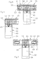
- the supports 32 serve for the combined fastening of additional plate-shaped components 67, in particular so-called wall protection elements, as well as the described or other handrail elements.
- the support surface 41 forms a means for mounting the handrail elements 1, 15 or 20, 60 while below the support surface 41 further means are provided for mounting at least one holding part 68, which is attached to the rear of the component 67 by means of at least one screw or the like is attached.
- the holding part 68 is provided on its underside with a rear projecting projection 69 and is thus hook-shaped.
- the means for mounting the holding part 68 has a holding web 70, into which the holding part 68 can be hung by its shoulder 69 engaging behind the holding web 70 in a hook-like manner, as shown in particular in FIG. 8.
- a stop surface 71 for the rear of component 67 is provided on said means or on support 32, which in the assembled state is arranged parallel to wall 31 and essentially vertically.
- the support 32 corresponds to the support according to FIG. 4, which is why the same parts are provided with the same reference numerals in FIGS. 8 and 9 and only the parts used for the assembly of the component 67 are explained below.
- the holding web 70 and the mounting surface 71 are at the lower end of a Mounting part 72 is provided, which is shell-shaped towards the component 67 and is connected at its rear to a base 73.
- the base 73 has, in an axially central part, a mounting plate 74 which is exactly the same size as the cover cap 49 (FIG. 4) and how it can be mounted in the recess 48.
- the base 73 On the component 67 side, the base 73 has a groove 75 which receives an assigned section of the mounting part 72 and defines its spatial position relative to the support 32.
- the position of the base 73 is predetermined by the position of the mounting plate 74 in the recess 48, ie the plate 74 replacing the cover cap 49 can be considered in this embodiment as part of the means for mounting the mounting part 68.
- a fastening screw 76 is used for fastening, which projects through a hole in the bottom of the groove 75 and in the associated section of the mounting part 72 and is screwed into a threaded bore in the lower part 33, which is formed, for example, by a press-in nut 77 which is fastened in the central section 35 of the lower part 33 becomes.
- a sleeve 78 provided on the rear of the base 73, which is supported on the central section 35, can serve as a spacer and transmit the forces exerted on the component 67 to the support 32.
- the component 67 is assembled in such a way that the support 32 is first installed with or without a handrail. Subsequently, the unit consisting of base 73 and mounting part 72 is fixed on the support 32 by means of the fastening screw 76, as a result of which the stop surface 71 is arranged vertically. Subsequently, the mounting part 68 fastened to the component 67 is hooked in by inserting the attachment 69 from above into a cavity behind the holding web 70. The component can be held in a vertical position throughout.
- the side walls of the mounting part 72 are provided in an upper region with transverse bores 79 (FIG. 9), into which a retaining pin 80 is inserted, which according to FIGS. 8 and 9 comes to lie in a space that is on the one hand the rear wall and upper lugs 81 of the mounting part 72 and on the other hand is limited by a holding surface 82 which is formed by a shoulder 82a formed at the upper end of the holding part 68.
- the cross bores 79 can be closed by plugs which have to be removed before the fastening of the holding part 68 can be released again.
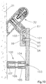
- the latter are provided in a lower region with at least one spacer 83.
- This consists e.g. from a lower part 84 fastened to the rear of the component 67 with a threaded bolt 85 projecting vertically backwards, onto which a threaded sleeve 86 is screwed, which carries at the free end a buffer insert 87 to be supported on the wall 81 made of an elastic material.
- the axial length of the spacer 83 can be changed and, at the same time, the component 67 in the lower region can be pivoted or braced outward about the support 32, as a result of which the holding part 68 is pressed more strongly into the mounting part 72 and an undesired lifting out of the component 67 from the mounting part 72 is safely avoided.
- the buffer insert 87 can also be designed as a large-area rosette which serves to reduce the surface pressure.
- the threaded sleeve 86 preferably consists, analogously to the handrail 1 (FIG. 1), of a metal tube 88 with a plastic jacket 89.
- An insert 90 with an internal thread is fastened in the metal tube 88, and the plastic jacket 89 is in a sleeve-like extension 91 on one on the lower part 84 clipped cover part 92 with a sliding fit.
- a compression spring 93 can be supported between the insert 90 and the lower part 84, which braces the threaded parts 85, 90 against one another and thus avoids undesired twisting of the threaded sleeve 86 or a loosening of the bracing of the component 67 due to vibrations or the like.
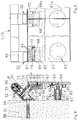
- each component 67 has two mounting parts 68 and 68a, which are expediently arranged at their lateral ends.
- the width of each mounting part 72 is dimensioned so large that it always receives the mounting parts 68, 68a of the two adjacent components 67, 67a at the joints between two components 67, 67a can. It is particularly desirable at the lateral ends of a wall section provided with components 67 to offset the mounting parts 72 parallel to the wall and in the horizontal direction relative to the supports 32 such that they are flush with their side walls, for example, as in FIG.
- the mounting parts 72 can be provided with several, optionally usable holes 94 for the fastening screw 76 (FIG. 8) or can be provided with an additional hole 94 at the construction site.
- mounting parts 96 fastened to the components 67 are provided with hook-shaped projections 97 in the lower region, at least stop surfaces 98 being formed on mounting parts 99 as inclined surfaces and being light in the assembled state are arranged obliquely to the wall 31 to enable the mounting of the mounting parts 96.
- This embodiment enables the components 67 to be hung in the pivoted state. If such a pivoting is not possible, e.g. in the area of a 90 ° corner, the embodiment according to FIGS. 8 and 9 is preferred.
- the components 67 would also align at an angle to the wall 31.
- the spacer 100 By setting the spacer 100 accordingly in FIG. 10, on the other hand, not only the component 67 is aligned vertically, but also the mounting part 96 in the mounting part 99 is pivoted such that an upper holding surface 101 on the mounting part 96 under a shoulder 102 attached to the front of the mounting part 99 comes to rest, whereby an unwanted loosening of the component 67 is prevented.
- the shoulder 102 would hinder or even make it impossible to mount the holding part 96.
- the spacer 100 consists of a lower part 104 with an external thread 105 inserted into the component 67 by means of a pin 103, on which a threaded bushing 106 is rotatably mounted with a buffer insert 107.
- the spacers are only loosely connected to the components 67 and are only supported on the wall 31 by means of the buffer inserts, which is possible because of the prestressing of the components 67 produced with them.
- the spacers 83 can also be firmly connected to the components 67 by means of additional screws. As a result, there are fewer loose parts and the spacers cannot fall off the components 67 during transport or the like. In addition, there is improved handling in connection with faster assembly.
- FIG. 11 schematically shows a spacer 109 which, if necessary, can be firmly attached to the wall 31 or the like by means of a stud 110.
- the stud 110 has a transverse bore on a section protruding from the wall 31.
- the spacer 109 which is otherwise designed like the spacer 83 (FIG. 8), is first brought into the desired position by rotating the threaded sleeve 86, the free end of the threaded sleeve 86 resting against the wall 31. Then a transverse pin 111 is inserted through the transverse bore of the stud 110 and a corresponding transverse bore of the threaded sleeve 86, which secures the position produced.
- the invention is not limited to the exemplary embodiments described, which can be modified in many ways. This applies, for example, with regard to axes 2 and 42 (FIG. 2), since exemplary embodiments are also conceivable in which the supports are used to mount the handrails of stairs and therefore do not run perpendicularly but rather obliquely to the longitudinal axis 40 (FIG. 4) Support surfaces 41 and axes 42 could have. It would also be possible, for example, to manufacture the mounting parts 72 and base 73 from one piece or as a preassembled structural unit. Furthermore, in the embodiments of FIGS.
- the plate-shaped components 67 and the parts serving to fasten them could be completely absent, while on the other hand the assembly of the plate-shaped components 67 according to FIGS. 8 to 11 also with the aid of supports can be made that support completely different handrail elements than those shown in the drawing, and for this purpose may also have completely different means than those shown.
- the components 67 can also be screwed directly through them Mounting part 72.99 are fastened, for example, by the fastening screw for the holding part 96 indicated in FIG. 10 being designed as a fastening screw screwed into the mounting part 99 and the holding part 97 being omitted. Should the screw heads lying on the visible side of the components 67 have a disruptive effect, they could be covered by appropriately designed cover caps. Furthermore, in FIGS.
- the cutout 48 can also be located at another convenient point, and the support surfaces 41 could also be positioned differently, in particular relative to the cutouts 48.
- the supports 32 or the lower and upper parts 33, 34 forming them with the support surfaces 41 are only one exemplary embodiment, especially since the support itself could also be designed as a one-piece hollow body.
Landscapes
- Engineering & Computer Science (AREA)
- Architecture (AREA)
- Civil Engineering (AREA)
- Structural Engineering (AREA)
- Supports Or Holders For Household Use (AREA)
- Steps, Ramps, And Handrails (AREA)
- Connection Of Plates (AREA)
- Fire-Detection Mechanisms (AREA)
- Handcart (AREA)
- Battery Mounting, Suspending (AREA)
- Patch Boards (AREA)
Applications Claiming Priority (2)
| Application Number | Priority Date | Filing Date | Title |
|---|---|---|---|
| DE29500542U DE29500542U1 (de) | 1995-01-14 | 1995-01-14 | Vorrichtung zur Befestigung eines plattenförmigen Bauteils an einer Wand o.dgl. |
| DE29500542U | 1995-01-14 |
Publications (3)
| Publication Number | Publication Date |
|---|---|
| EP0722026A2 true EP0722026A2 (fr) | 1996-07-17 |
| EP0722026A3 EP0722026A3 (fr) | 1996-11-13 |
| EP0722026B1 EP0722026B1 (fr) | 2000-07-12 |
Family
ID=8002502
Family Applications (1)
| Application Number | Title | Priority Date | Filing Date |
|---|---|---|---|
| EP96100427A Expired - Lifetime EP0722026B1 (fr) | 1995-01-14 | 1996-01-12 | Dispositif pour la fixation d'un élément de construction en forme de plaque sur un mur ou similaire |
Country Status (4)
| Country | Link |
|---|---|
| EP (1) | EP0722026B1 (fr) |
| AT (1) | ATE194678T1 (fr) |
| DE (2) | DE29500542U1 (fr) |
| ES (1) | ES2150602T3 (fr) |
Families Citing this family (2)
| Publication number | Priority date | Publication date | Assignee | Title |
|---|---|---|---|---|
| FR2750588B1 (fr) * | 1996-07-04 | 1998-09-18 | Mapal Sa | Barriere basse de protection anti-choc pour meubles de vente et applications analogues |
| DE20212290U1 (de) * | 2002-08-09 | 2003-12-18 | Franz Viegener Ii Gmbh & Co. Kg | Halterung zur Befestigung von Montagegestellen |
Citations (3)
| Publication number | Priority date | Publication date | Assignee | Title |
|---|---|---|---|---|
| DE9307992U1 (de) * | 1993-05-27 | 1993-08-12 | Wormuth, Armin, 10587 Berlin | Trägerelement für einen horizontal längs verlaufenden Wandschutz, insbesondere für Krankenhäuser o.dgl. |
| DE4300997A1 (de) * | 1993-01-15 | 1994-07-21 | Wilke Heinrich Hewi Gmbh | Vorrichtung zur Befestigung eines plattenförmigen Bauteils an einer Wand o. dgl. |
| EP0657600A2 (fr) * | 1993-12-08 | 1995-06-14 | Construction Specialties, Inc. | Butoir/Main courante ergonomique |
-
1995
- 1995-01-14 DE DE29500542U patent/DE29500542U1/de not_active Expired - Lifetime
-
1996
- 1996-01-12 AT AT96100427T patent/ATE194678T1/de active
- 1996-01-12 DE DE59605556T patent/DE59605556D1/de not_active Expired - Fee Related
- 1996-01-12 EP EP96100427A patent/EP0722026B1/fr not_active Expired - Lifetime
- 1996-01-12 ES ES96100427T patent/ES2150602T3/es not_active Expired - Lifetime
Patent Citations (3)
| Publication number | Priority date | Publication date | Assignee | Title |
|---|---|---|---|---|
| DE4300997A1 (de) * | 1993-01-15 | 1994-07-21 | Wilke Heinrich Hewi Gmbh | Vorrichtung zur Befestigung eines plattenförmigen Bauteils an einer Wand o. dgl. |
| DE9307992U1 (de) * | 1993-05-27 | 1993-08-12 | Wormuth, Armin, 10587 Berlin | Trägerelement für einen horizontal längs verlaufenden Wandschutz, insbesondere für Krankenhäuser o.dgl. |
| EP0657600A2 (fr) * | 1993-12-08 | 1995-06-14 | Construction Specialties, Inc. | Butoir/Main courante ergonomique |
Also Published As
| Publication number | Publication date |
|---|---|
| EP0722026B1 (fr) | 2000-07-12 |
| EP0722026A3 (fr) | 1996-11-13 |
| ATE194678T1 (de) | 2000-07-15 |
| DE59605556D1 (de) | 2000-08-17 |
| DE29500542U1 (de) | 1996-05-15 |
| ES2150602T3 (es) | 2000-12-01 |
Similar Documents
| Publication | Publication Date | Title |
|---|---|---|
| AT404219B (de) | Schublade | |
| DE2348239A1 (de) | Gestellanordnung | |
| EP0705375B1 (fr) | Système de fixation pour panneaux de façade | |
| EP0501148B1 (fr) | Système d'assemblage pour deux éléments fabriqués en tube ou tige et/ou éléments ayant des jonctions | |
| DE4030978C2 (de) | Verbindungseinrichtung für Rohre | |
| EP0333772B1 (fr) | Systeme modulaire de construction | |
| DE3132855A1 (de) | Rosetten-unterteil | |
| DD299202A5 (de) | Vorrichtung zur befestigung eines insbesondere rohrfoermigen bauteils an einer wand oder dgl. | |
| EP0477707B1 (fr) | Dispositif d'assemblage notamment pour d'une pièce de construction tubulaire | |
| DE69210796T3 (de) | Klammer, insbesondere zur Befestigung von Heizkörpern | |
| DE4210488A1 (de) | Verbindungseinrichtung für ein insbesondere rohrförmiges Bauteil | |
| DE3521783C1 (de) | Abstandsbüchse für die Befestigung eines Beschlagteils an einem mit einem vorgesetzten Profilteil versehenen Hohlprofil | |
| EP0475216A1 (fr) | Dispositif d'assemblage entre des poutres et des noeuds d'une structure tridimensionelle | |
| EP0722026B1 (fr) | Dispositif pour la fixation d'un élément de construction en forme de plaque sur un mur ou similaire | |
| DE102007014484B4 (de) | Vorrichtung zum lösbaren Verbinden | |
| DE3301478C2 (de) | Vorrichtung zum Befestigen eines rohr- oder stangenförmigen Bauteils an einer Montagefläche | |
| DE1942604A1 (de) | Einrichtung zum Verankern eines Teiles an einem anderen Teil eines Baukoerpers | |
| DE3922961A1 (de) | Abstandshalter zum halten von beiderseits einer zu errichtenden betonwand aufgestellten schaltafeln im wandabstand zueinander | |
| DE3147092C2 (de) | Verbindungssystem mit wenigstens einem Eckbogenelement | |
| DE202014010156U1 (de) | Befestigungselement zur Befestigung von Anbauteilen an gedämmten Gebäudewänden | |
| EP0723052A2 (fr) | Main courante | |
| EP2425066B1 (fr) | Cloisonnement pour aménagement intérieur | |
| AT405561B (de) | Plattenbefestigungselement | |
| DE9302897U1 (de) | Dübel zur Befestigung von Lasten an Hohlraumdecken | |
| DE2734520C3 (de) | Schalungszuganker aus Kunststoff |
Legal Events
| Date | Code | Title | Description |
|---|---|---|---|
| PUAI | Public reference made under article 153(3) epc to a published international application that has entered the european phase |
Free format text: ORIGINAL CODE: 0009012 |
|
| AK | Designated contracting states |
Kind code of ref document: A2 Designated state(s): AT BE CH DE ES FR GB IT LI LU NL |
|
| PUAL | Search report despatched |
Free format text: ORIGINAL CODE: 0009013 |
|
| AK | Designated contracting states |
Kind code of ref document: A3 Designated state(s): AT BE CH DE ES FR GB IT LI LU NL |
|
| 17P | Request for examination filed |
Effective date: 19970417 |
|
| GRAG | Despatch of communication of intention to grant |
Free format text: ORIGINAL CODE: EPIDOS AGRA |
|
| 17Q | First examination report despatched |
Effective date: 19990629 |
|
| GRAG | Despatch of communication of intention to grant |
Free format text: ORIGINAL CODE: EPIDOS AGRA |
|
| GRAH | Despatch of communication of intention to grant a patent |
Free format text: ORIGINAL CODE: EPIDOS IGRA |
|
| GRAH | Despatch of communication of intention to grant a patent |
Free format text: ORIGINAL CODE: EPIDOS IGRA |
|
| GRAA | (expected) grant |
Free format text: ORIGINAL CODE: 0009210 |
|
| AK | Designated contracting states |
Kind code of ref document: B1 Designated state(s): AT BE CH DE ES FR GB IT LI LU NL |
|
| REF | Corresponds to: |
Ref document number: 194678 Country of ref document: AT Date of ref document: 20000715 Kind code of ref document: T |
|
| REG | Reference to a national code |
Ref country code: CH Ref legal event code: NV Representative=s name: E. BLUM & CO. PATENTANWAELTE Ref country code: CH Ref legal event code: EP |
|
| REF | Corresponds to: |
Ref document number: 59605556 Country of ref document: DE Date of ref document: 20000817 |
|
| ITF | It: translation for a ep patent filed | ||
| GBT | Gb: translation of ep patent filed (gb section 77(6)(a)/1977) |
Effective date: 20000914 |
|
| ET | Fr: translation filed | ||
| REG | Reference to a national code |
Ref country code: ES Ref legal event code: FG2A Ref document number: 2150602 Country of ref document: ES Kind code of ref document: T3 |
|
| PGFP | Annual fee paid to national office [announced via postgrant information from national office to epo] |
Ref country code: GB Payment date: 20010110 Year of fee payment: 6 |
|
| PGFP | Annual fee paid to national office [announced via postgrant information from national office to epo] |
Ref country code: AT Payment date: 20010122 Year of fee payment: 6 |
|
| PGFP | Annual fee paid to national office [announced via postgrant information from national office to epo] |
Ref country code: ES Payment date: 20010124 Year of fee payment: 6 |
|
| PGFP | Annual fee paid to national office [announced via postgrant information from national office to epo] |
Ref country code: CH Payment date: 20010125 Year of fee payment: 6 |
|
| PGFP | Annual fee paid to national office [announced via postgrant information from national office to epo] |
Ref country code: LU Payment date: 20010129 Year of fee payment: 6 |
|
| PGFP | Annual fee paid to national office [announced via postgrant information from national office to epo] |
Ref country code: FR Payment date: 20010130 Year of fee payment: 6 Ref country code: BE Payment date: 20010130 Year of fee payment: 6 |
|
| PGFP | Annual fee paid to national office [announced via postgrant information from national office to epo] |
Ref country code: NL Payment date: 20010131 Year of fee payment: 6 |
|
| PGFP | Annual fee paid to national office [announced via postgrant information from national office to epo] |
Ref country code: DE Payment date: 20010328 Year of fee payment: 6 |
|
| PLBE | No opposition filed within time limit |
Free format text: ORIGINAL CODE: 0009261 |
|
| STAA | Information on the status of an ep patent application or granted ep patent |
Free format text: STATUS: NO OPPOSITION FILED WITHIN TIME LIMIT |
|
| 26N | No opposition filed | ||
| REG | Reference to a national code |
Ref country code: GB Ref legal event code: IF02 |
|
| PG25 | Lapsed in a contracting state [announced via postgrant information from national office to epo] |
Ref country code: LU Free format text: LAPSE BECAUSE OF NON-PAYMENT OF DUE FEES Effective date: 20020112 Ref country code: GB Free format text: LAPSE BECAUSE OF NON-PAYMENT OF DUE FEES Effective date: 20020112 Ref country code: AT Free format text: LAPSE BECAUSE OF NON-PAYMENT OF DUE FEES Effective date: 20020112 |
|
| PG25 | Lapsed in a contracting state [announced via postgrant information from national office to epo] |
Ref country code: ES Free format text: LAPSE BECAUSE OF NON-PAYMENT OF DUE FEES Effective date: 20020113 |
|
| PG25 | Lapsed in a contracting state [announced via postgrant information from national office to epo] |
Ref country code: LI Free format text: LAPSE BECAUSE OF NON-PAYMENT OF DUE FEES Effective date: 20020131 Ref country code: CH Free format text: LAPSE BECAUSE OF NON-PAYMENT OF DUE FEES Effective date: 20020131 Ref country code: BE Free format text: LAPSE BECAUSE OF NON-PAYMENT OF DUE FEES Effective date: 20020131 |
|
| BERE | Be: lapsed |
Owner name: HEINRICH WILKE G.M.B.H. HEWI Effective date: 20020131 |
|
| PG25 | Lapsed in a contracting state [announced via postgrant information from national office to epo] |
Ref country code: NL Free format text: LAPSE BECAUSE OF NON-PAYMENT OF DUE FEES Effective date: 20020801 Ref country code: DE Free format text: LAPSE BECAUSE OF NON-PAYMENT OF DUE FEES Effective date: 20020801 |
|
| GBPC | Gb: european patent ceased through non-payment of renewal fee |
Effective date: 20020112 |
|
| REG | Reference to a national code |
Ref country code: CH Ref legal event code: PL |
|
| PG25 | Lapsed in a contracting state [announced via postgrant information from national office to epo] |
Ref country code: FR Free format text: LAPSE BECAUSE OF NON-PAYMENT OF DUE FEES Effective date: 20020930 |
|
| NLV4 | Nl: lapsed or anulled due to non-payment of the annual fee |
Effective date: 20020801 |
|
| REG | Reference to a national code |
Ref country code: FR Ref legal event code: ST |
|
| REG | Reference to a national code |
Ref country code: ES Ref legal event code: FD2A Effective date: 20030211 |
|
| PG25 | Lapsed in a contracting state [announced via postgrant information from national office to epo] |
Ref country code: IT Free format text: LAPSE BECAUSE OF NON-PAYMENT OF DUE FEES;WARNING: LAPSES OF ITALIAN PATENTS WITH EFFECTIVE DATE BEFORE 2007 MAY HAVE OCCURRED AT ANY TIME BEFORE 2007. THE CORRECT EFFECTIVE DATE MAY BE DIFFERENT FROM THE ONE RECORDED. Effective date: 20050112 |