EP0721806B1 - Vorrichtung zur Detektion der Anwesenheit eines harten Gegenstandes in einem Poststück - Google Patents
Vorrichtung zur Detektion der Anwesenheit eines harten Gegenstandes in einem Poststück Download PDFInfo
- Publication number
- EP0721806B1 EP0721806B1 EP96400068A EP96400068A EP0721806B1 EP 0721806 B1 EP0721806 B1 EP 0721806B1 EP 96400068 A EP96400068 A EP 96400068A EP 96400068 A EP96400068 A EP 96400068A EP 0721806 B1 EP0721806 B1 EP 0721806B1
- Authority
- EP
- European Patent Office
- Prior art keywords
- envelope
- bend
- conveyor
- fold
- sensor
- Prior art date
- Legal status (The legal status is an assumption and is not a legal conclusion. Google has not performed a legal analysis and makes no representation as to the accuracy of the status listed.)
- Expired - Lifetime
Links
Images

Classifications
-
- B—PERFORMING OPERATIONS; TRANSPORTING
- B07—SEPARATING SOLIDS FROM SOLIDS; SORTING
- B07C—POSTAL SORTING; SORTING INDIVIDUAL ARTICLES, OR BULK MATERIAL FIT TO BE SORTED PIECE-MEAL, e.g. BY PICKING
- B07C1/00—Measures preceding sorting according to destination
- B07C1/10—Sorting according to size or flexibility
- B07C1/16—Sorting according to thickness or stiffness
Definitions
- the invention relates to a device for detecting the presence of a hard object inserted inside a envelope.
- the invention applies in particular to automatic processing of mail folds, such as postal sorting.
- conveyor belts which define a relatively fold fold conveying path complicated including several 90 ° and even 180 ° turns.
- Mail folds are usually made up a flexible and flat envelope containing sheets of flexible paper themselves so that the folds flex easily in the bends of the path.
- the mail folds have thicknesses generally varying between 0.15 to 8 mm and a goal of the invention is to provide a device capable of detecting the presence of a hard object in thick folds variable.
- the invention relates to a device to detect the presence of a hard object inserted at the interior of an envelope having a certain thickness.
- This device includes a conveyor for moving the envelope following a direction of travel along a path including a turn.
- An organ is arranged outside the turn and downstream of it following said direction of movement to cooperate with the conveyor in order to force the envelope to flex in the turn.
- This organ is mounted movable relative to the conveyor so as to occupy a first position offset from the conveyor by a first distance substantially equal to the thickness of the envelope before it enters the bend and a second position offset from the first position by a certain distance when the envelope passes through the turn.
- a captor is intended to detect that said certain distance is above a predetermined threshold, on the basis of which the presence of a hard object inside the envelope is detected. Since this organ is previously removed from the conveyor according to the thickness of the envelope to treat, he is not subject to violent contact with the edge of the envelope, so the displacement of this organ does not integrate the kinetic energy that can be generated by such contact. This situation is particularly critical in a sorting facility postal where mail folds are moved to very large speed. A second member placed outside the bend and upstream thereof in said direction of travel suitable for first moving the first organ arranged downstream of the turn by a substantially equal distance to the thickness of the envelope.
- this second the member is itself mounted movable relative to the conveyor and is coupled in movement with the first organ by a elastic mechanical connection able to absorb shocks which the second organ undergoes and which are transmitted to the first organ.
- this mechanical connection includes a telescopic link and a return spring which acts against the removal of the first organ by report to the second organ.
- a sensor arranged to detect that the relative distance between the first and second organ is greater than a predetermined threshold can serve as a basis for detecting the presence of hard objects in the envelopes.
- Figure 1 shows schematically the device according the invention in the rest position.
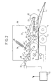
- Figure 2 schematically shows the device of the figure 1 crossed by a thin fold containing a hard object.
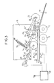
- Figure 3 schematically shows the device of the Figure 1 crossed by a very thick fold.
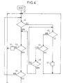
- Figure 4 is a flowchart illustrating the operation of the device according to the invention.
- the device according to the invention is used to detect the presence of a hard object, such as a metal plate, inserted inside a flexible envelope of paper or the like, like the envelope of a mail fold.
- a hard object such as a metal plate
- hard objects inserted into the envelopes of the folds usually have a length of at least 50mm, thickness of at least 1mm and withstand a bending force of around 400Nmm. We understands that this kind of hard object stiffens a fold of mail which can then damage or block a conveyor bands.
- a conveyor defines a straight path followed by a turn at around 10 °.
- the conveyor includes here a rigid band 1 engaging on rotary rollers 2 and 3 (or pulleys) which here have fixed axes of rotation.
- the roller 3 defines the interior of the turn.
- the belt conveyor 1 is part of an installation more complex handling of mail folds and is found upstream of the mail fold processing line.
- a set of organs is arranged outside the turn to cooperate with the belt conveyor 1 in order to constrain a mail fold, moved by the conveyor in direction D, to flex in the bend, that is to say to follow the curvature of the turn.
- the set of organs here comprises three rollers 10,11,12 rotatably mounted at the end of swing arms respective 13,14,15.
- These arms 13, 14, 15 are mounted at rotation on respective axes 13 ', 14', 15 'integral a plate 16 attached to the frame of the conveyor belt 1.
- the arms 13 to 15 are inclined, when they occupy their rest position, at an angle of about 45 ° from the direction D and an endless elastic band 17 engages on the rollers 10 to 12 facing the strip 1.
- This strip 17 is held taut by other rollers not shown and helps to reduce the intensity of contact between a fold arriving at high speed and the roller 10.
- the arms 13 and 14 carrying the rollers 10 and 11 placed upstream of the turn are coupled by a link 18 which unites their oscillating movements.
- the axes of rotation 13 'and 14' of the arms 13 and 14 respectively are aligned parallel to the link 18 and to a straight portion of the journey located upstream of the turn. So when passing a fold through the portion straight path, the roller 10 deviates from the strip 1 by a distance substantially equal to the thickness of the fold and simultaneously, the roller 11 deviates by the same distance from the strip 1 to free a space for the fold between the bands 1 and 17.
- the return spring 19 is very slightly prestressed and a stop 20 is placed on plate 16 to limit the movement of the arm 13 along the arrow D "so that keep the rollers 10 and 11 about 1mm from the strip 1.
- roller 12 placed downstream of the turn and cooperating with the conveyor to constrain the fold to bend in this turn is coupled in motion with the roller 11 by an elastic mechanical connection 21 comprising a telescopic link 22 whose ends are here coupled to the movable axes of the rollers 11 and 12.
- This telescopic link is arranged to maintain a minimum distance between the axes of rotation of the rollers 11 and 12 and a return spring 23, mounted inside the rod for example, acts against the elongation of the rod, that is to say against the relative distance of the roller 11 relative to roller 12 under the action of a fold rigid passing through the bend.
- roller 10 and by reaction the roller 11
- the roller 12 is simultaneously removed by this same distance from the belt 1 of the conveyor under the action of the rod 22.
- a stop 24 fixed on the plate 16 and cooperating with the arm 15 serves to limit the movement of the roller 12 in the direction of the strip 1 under the action of the return spring 23 weakly prestressed so as to keep the roller 12 at about 3mm of band 1.
- Figure 1 the device occupies a rest position in the absence of a fold on the way.
- Figure 2 when a fold P1 thin but containing a hard object arrives in the straight portion of the path, the rollers 10 to 12 do not almost deviate from the conveyor due to the low thickness of fold P1.
- fold P1 arrives in the bend, the rollers 10 and 11 still press on the part back of the fold now this one parallel to the portion straight path, while the roller 12 deviates gradually from the conveyor because it is pushed by the hard object in the fold and that the return spring 23 has a lower stiffness coefficient than the return spring 19.
- the roller 12 occupies substantially the same position between the instant when a flexible fold arrives in entering the bend and the moment when this flexible fold passes into the bend regardless of its thickness.
- the pebble 12 occupies different positions between the moment when a rigid fold arrives at the entrance to the turn and the instant when this fold rigid going around the bend. It's the change of position of the roller 12 between these two instants which serves as a basis for the detection of the presence of a hard object in a fold subjected to a bending stress by this roller 12. A change of position of the roller 12 between these two instants is reflected also by varying the relative distance between the rollers 11 and 12.
- a sensor is provided for detecting that a movement of the roller 12 between the position it occupies before the fold arrives at the entrance to the turn and the position that it occupies when the fold passes in the bend. If the distance between these two positions is greater than a threshold predetermined fixed for example at 2mm, the presence of an object hard in the crease will be detected.
- the senor is mounted on the rollers 11 and 12 to detect that the relative distance between the rollers 11 and 12 is above the predetermined threshold on the basis of which the presence of a hard object in the analyzed fold is detected.
- a such a sensor consists for example of a transmitter / receiver photodetection 30 placed on the axis of rotation of the roller 11 and operating in all or nothing with a reflector placed on the axis of rotation of the roller 12.
- the sensor consists of a fork cell of photodetection placed on the axis of the roller 11 and operating all or nothing with a flag placed on the axis of the roller 12.
- a position sensor 31, of the photodetection type is placed at a point in the straight portion of the path for detect the passage of the front edge of the fold and the passage of the back edge of this fold.
- Another sensor 32 is provided for detect that the thickness of the fold is greater than a threshold predetermined, for example 5mm (in the case of a thick fold).
- This sensor 32 is for example a photodetection cell transmitter / receiver placed on plate 4 and operating all or nothing with a reflector mounted on the end of the arm 13.
- the outputs of sensors 30, 31 and 32 are supplied to a data processing unit 33 which, depending on the output from these sensors, provides a signal S indicative of the presence of a hard object in the fold analyzed.
- FIG. 4 the operation of unit 4 is illustrated by an organization chart.
- the passage of the front edge of a fold under the roller 11 is detected in response to the output of the sensor 31 following what, at 41, the output of the sensor 32 is tested. If the sensor 32 detects the presence of a thick fold, the processing continues in 42. Otherwise, the exit from sensor 30 is tested at 50. Note that at this instant the fold is in the bend. If the sensor 30 detects the presence of a rigid fold, the processing unit makes a signal S in 51 indicative of the presence of a hard object in the fold coming out of the bend. Otherwise the treatment continues at step 52.
- the processing unit does not give an indicative signal S the presence of a hard object in the fold coming out of the turn and processing loops on step 40 awaiting passage a new fold under the roller 11. Otherwise, the treatment loop on test step 41. Note that thus, the presence a hard object located in the back of a fold of thin or in the middle part of this fold or still in the front part of this fold will be detected by the processing unit.
- a thick fold was detected by sensor 32.
- the output of sensor 30 is tested. If the sensor 30 detects the presence of a fold rigid, the processing unit provides an S signal at 43 indicative of the presence of a hard object in the fold. To note that in this case it is possible that the thick and rigid fold does not contain hard objects. If the sensor 30 does not detect not the presence of a rigid fold at 42, the sensor output 31 is tested at 44. At 44, if the passage of the rear edge of the crease under the roller 11 is detected, processing continues in step 40. Note that this case corresponds to the detection of a thick flexible pleat. Otherwise, the output of sensor 32 is tested in 45, the fold being in the bend.
- the loop processing on test step 42 for detection possible a hard object located behind the thick fold. Otherwise, the processing loops to step 50.
- it is a fold of variable thickness that can contain a hard object in its rear part.
- the signal S can be used as a control signal for a referral system following the turn which reroutes each fold detected as containing a hard object to a storage area by example.
Landscapes
- Controlling Sheets Or Webs (AREA)
- Sorting Of Articles (AREA)
- Geophysics And Detection Of Objects (AREA)
- Sheets, Magazines, And Separation Thereof (AREA)
Claims (7)
- Eine Vorrichtung zur Detektion der Anwesenheit eines harten Gegenstandes im Inneren eines Umschlags (P1, P2) mit einer bestimmten Dicke, die einen Förderer (1) zur Bewegung des Umshlags in einer Bewegungsrichtung (D) entlang einer eine Kurve umfassenden Strecke, ein in Bezug auf den Förderer beweglich montiertes und hinter diesem entsprechend der genannten Bewegungsrichtung angebrachtes Organ, das mit dem Förderer zusammenwirken soll, um den Umschlag zu zwingen, sich in der Kurve zu biegen, und einen die Bewegung des genannten Organs registrierenden Meßfühler zur Detektion der Anwesenheit eines harten Gegenstandes im Umschlag umfaßt, dadurch gekennzeichnet, daß dieses Organ außerhalb der Kurve angeordnet und in Bezug auf den Förderer beweglich montiert ist, so daß es eine erste zum Förderer um einen ersten, im wesentlichen der Dicke des Umschlags entsprechenden Abstand versetzte Position einnimmt, bevor der Umschlag in die Kurve eintritt, und eine zweite Position, die von der ersten Position um einen bestimmten Abstand versetzt ist, wenn der Umschlag sich in die Kurve bewegt, wobei der genannte Meßfühler (30) feststellt, daß der genannte bestimmte Abstand größer als ein vorher festgelegter Grenzwert ist und auf dieser Grundlage die Anwesenheit eines harten Gegenstands im Inneren des Umschlags festgestellt wird.
- Vorrichtung gemäß nach Anspruch 1, die ein zweites, außerhalb der Kurve und vor ihr in der genannten Bewegungsrichtung angeordnetes Organ (11) umfaßt, wobei dieses zweite Organ (11) in Bezug auf den Förderer beweglich montiert und in der Bewegung an das hinter der Kurve angeordnete erste Organ gekoppelt ist, so daß es sich unter Einwirkung des in der Kurve ankommenden Umschlags um einen Abstand verschiebt, der im wesentlichen gleich der Dicke des Umschlags ist, und seine Verschiebungsbewegung auf das genannte erste Organ überträgt, um letzteres in seine erste Position zu verschieben.
- Vorrichtung gemäß Anspruch 2, nach dem das erste (12) und das zweite (11) Organ in der Bewegung durch eine mechanische elastische Verbindung (21) miteinander gekoppelt sind.
- Vorrichtung gemäß Anspruch 3, nach dem die mechanische elastische Verbindung (21) eine Teleskopstange (22) und eine Rückholfeder (23) umfaßt, die dem Entfernen des ersten Organs in Bezug auf das zweite Organ entgegenwirkt.
- Vorrichtung gemäß einem beliebigen der Ansprüche 2 bis 4, nach dem der Meßfühler (30) vorgesehen ist, um festzustellen, ob der relative Abstand zwischen dem ersten und dem zweiten Organ größer ist als der vorher festgelegte Grenzwert.
- Vorrichtung gemäß einem beliebigen der Ansprüche 2 bis 5, nach dem das genannte erste (12) und das genannte zweite (11) Organ umlaufende Rollen sind, auf denen ein elastisches Endlosband (17) liegt.
- Vorrichtung gemäß einem beliebigen der Ansprüche 2 bis 6, die einen ersten Meßfühler (30) zur Feststellung, ob der relative Abstand zwischen dem ersten Organ (12) und dem zweiten Organ (11) größer ist als ein erster vorher festgelegter Grenzwert, einen zweiten Meßfühler (32) zur Feststellung, ob die Dicke des Umschlags größer ist als ein zweiter vorher festgelegter Grenzwert, einen dritten Meßfühler (31) zur Feststellung des Durchlaufs des Umschlags hinter der Kurve in der Sewegungsrichtung und einen Datenverarbeitungseinheit (33) umfaßt, die als Reaktion auf die die Ausgangswerte des genannten ersten, zweiten und dritten Meßfühlers ein Signal (S) zur Anzeige der Anwesenheit eines harten Gegenstands im Inneren des Umschlags liefert.
Applications Claiming Priority (2)
| Application Number | Priority Date | Filing Date | Title |
|---|---|---|---|
| FR9500311 | 1995-01-12 | ||
| FR9500311A FR2729310A1 (fr) | 1995-01-12 | 1995-01-12 | Dispositif pour detecter la presence d'un objet dur dans un pli de courrier |
Publications (2)
| Publication Number | Publication Date |
|---|---|
| EP0721806A1 EP0721806A1 (de) | 1996-07-17 |
| EP0721806B1 true EP0721806B1 (de) | 2000-07-12 |
Family
ID=9475079
Family Applications (1)
| Application Number | Title | Priority Date | Filing Date |
|---|---|---|---|
| EP96400068A Expired - Lifetime EP0721806B1 (de) | 1995-01-12 | 1996-01-11 | Vorrichtung zur Detektion der Anwesenheit eines harten Gegenstandes in einem Poststück |
Country Status (8)
| Country | Link |
|---|---|
| US (1) | US5637811A (de) |
| EP (1) | EP0721806B1 (de) |
| AT (1) | ATE194514T1 (de) |
| CA (1) | CA2167009A1 (de) |
| DE (1) | DE69609205T2 (de) |
| ES (1) | ES2149431T3 (de) |
| FR (1) | FR2729310A1 (de) |
| WO (1) | WO1996021524A1 (de) |
Cited By (1)
| Publication number | Priority date | Publication date | Assignee | Title |
|---|---|---|---|---|
| CN109592364A (zh) * | 2018-11-06 | 2019-04-09 | 上海洪海实业发展有限公司 | 物料定长检测装置 |
Families Citing this family (10)
| Publication number | Priority date | Publication date | Assignee | Title |
|---|---|---|---|---|
| DE19600231C2 (de) * | 1996-01-05 | 1998-02-19 | Siemens Ag | Vorrichtung und Verfahren zur Steifigkeitsmessung von flachen Sendungen |
| FR2745102B1 (fr) * | 1996-02-16 | 1998-03-20 | Cga Hbs | Dispositif de filtre d'epaisseur dans une goulotte d'introduction d'un lecteur de titres tels que tickets, cartes |
| JP3006531B2 (ja) * | 1997-03-24 | 2000-02-07 | 日本電気株式会社 | 半導体装置の製造方法 |
| DE10141375C1 (de) | 2001-08-23 | 2003-03-13 | Siemens Dematic Ag | Vorrichtung zum Trennen von Sendungen in Dickenklassen |
| DE50308558D1 (de) * | 2002-09-27 | 2007-12-20 | Siemens Ag | Vorrichtung zur messung der biegesteifigkeit von flachen sendungen |
| US7315007B2 (en) * | 2003-06-09 | 2008-01-01 | Siemens Dematic Corp. | Method and apparatus for stiffness and thickness detection in mail sorting systems |
| FR2856088B1 (fr) * | 2003-06-11 | 2005-09-09 | Cie Du Sol | Outil de fraisage pour la realisation de tranchees, permettant un changement rapide de la tete de coupe |
| US7232070B2 (en) * | 2004-06-10 | 2007-06-19 | Lockheed Martin Corporation | Chemical/biological hazard trigger with automatic mail piece tagging system and method |
| US7669470B2 (en) * | 2007-07-09 | 2010-03-02 | Siemens Industry, Inc. | Mail piece stiffness detector |
| JP5148265B2 (ja) * | 2007-12-27 | 2013-02-20 | 株式会社東芝 | 区分装置及び区分装置の制御方法 |
Family Cites Families (8)
| Publication number | Priority date | Publication date | Assignee | Title |
|---|---|---|---|---|
| GB854543A (en) * | 1958-04-29 | 1960-11-23 | Thrissell Engineering Company | Improvements in letter sorting machines |
| DE1774194A1 (de) * | 1969-04-30 | 1971-12-16 | Telefunken Patent | Einrichtung zum selbsttaetigen Sortieren von Briefen und aehnlichen flachen Gegenstaenden nach ihrer Steife |
| US4063283A (en) * | 1975-04-03 | 1977-12-13 | Chemetron Corporation | Automatic envelope measuring system |
| US4361029A (en) * | 1980-05-27 | 1982-11-30 | Computer Peripherals, Inc. | Pneumatic radius sensor |
| US4360108A (en) * | 1981-01-05 | 1982-11-23 | Joule' Technical Corporation | Method and apparatus for checking letter thickness |
| US4516264A (en) * | 1982-01-29 | 1985-05-07 | United States Of America Postal Service | Apparatus and process for scanning and analyzing mail information |
| US4576287A (en) * | 1982-09-10 | 1986-03-18 | Omation Corporation | Apparatus and method for checking the contents of envelopes and sorting documents by thickness |
| NL181338C (nl) * | 1983-06-13 | 1987-08-03 | Nederlanden Staat | Controle-inrichting voor het onderzoeken van brieven. |
-
1995
- 1995-01-12 FR FR9500311A patent/FR2729310A1/fr active Granted
-
1996
- 1996-01-11 AT AT96400068T patent/ATE194514T1/de not_active IP Right Cessation
- 1996-01-11 ES ES96400068T patent/ES2149431T3/es not_active Expired - Lifetime
- 1996-01-11 WO PCT/FR1996/000047 patent/WO1996021524A1/fr not_active Ceased
- 1996-01-11 EP EP96400068A patent/EP0721806B1/de not_active Expired - Lifetime
- 1996-01-11 DE DE69609205T patent/DE69609205T2/de not_active Expired - Fee Related
- 1996-01-11 US US08/585,432 patent/US5637811A/en not_active Expired - Fee Related
- 1996-01-11 CA CA002167009A patent/CA2167009A1/fr not_active Abandoned
Cited By (1)
| Publication number | Priority date | Publication date | Assignee | Title |
|---|---|---|---|---|
| CN109592364A (zh) * | 2018-11-06 | 2019-04-09 | 上海洪海实业发展有限公司 | 物料定长检测装置 |
Also Published As
| Publication number | Publication date |
|---|---|
| WO1996021524A1 (fr) | 1996-07-18 |
| US5637811A (en) | 1997-06-10 |
| AU4542796A (en) | 1996-07-31 |
| ATE194514T1 (de) | 2000-07-15 |
| AU692664B2 (en) | 1998-06-11 |
| DE69609205D1 (de) | 2000-08-17 |
| ES2149431T3 (es) | 2000-11-01 |
| CA2167009A1 (fr) | 1996-07-13 |
| FR2729310B1 (de) | 1997-02-14 |
| EP0721806A1 (de) | 1996-07-17 |
| FR2729310A1 (fr) | 1996-07-19 |
| DE69609205T2 (de) | 2001-03-08 |
Similar Documents
| Publication | Publication Date | Title |
|---|---|---|
| EP0721806B1 (de) | Vorrichtung zur Detektion der Anwesenheit eines harten Gegenstandes in einem Poststück | |
| US6141883A (en) | Apparatus for detecting the thickness of documents | |
| US6000693A (en) | Article detection via pinch-roll motion | |
| EP1714110B1 (de) | Verfahren und vorrichtung zur messung der dicke eines poststücks | |
| WO2011157919A1 (fr) | Dispositif d'empilage d'objets plats sur chant et machine de tri postal équipée d'au moins un tel dispositif | |
| EP0728669A1 (de) | Automatische Etikettiervorrichtung für Produkte | |
| FR2868760A1 (fr) | Dispositif de convoyage a courroie vrillee deux fois et a poulie de tension flottante | |
| FR2720535A1 (fr) | Dispositif de lecture par machine d'informations apposées sur des objets plats. | |
| EP2424802B1 (de) | Verfahren zur erkennung geöffneter postsendungen, z.b. umschlagloser magazine | |
| EP2465702B1 (de) | Vorrichtung zum Zuschneiden von Umschlägen | |
| FR2849188A1 (fr) | Dispositif pour la pesee dynamique d'envois postaux | |
| EP3807021A2 (de) | System zur auswahl von objekten, die sich entlang einer transferlinie bewegen | |
| AU781317B2 (en) | Take-away mechanism for mail or other flat article handling system | |
| US5810154A (en) | Low actuation force article sensor for conveyor | |
| CA2163832A1 (fr) | Detecteur d'enveloppe en plastique et equipement de traitement d'articles plats incluant un tel detecteur | |
| WO2001076775A1 (fr) | Procede acoustique pour discriminer des enveloppes en papier et en matiere plastique | |
| EP1686540B1 (de) | Mechanische Vorrichtung zur Messung der Breite eines Postartikels | |
| EP1724729B1 (de) | Vorrichtung zur Breitenmessung mittels des Lichtdämpfungsunterschieds | |
| GB2430973A (en) | Letterbox conveyor apparatus | |
| FR2679884A1 (fr) | Machine de traitement d'objets plats. | |
| JPS62222950A (ja) | 紙葉類の折れ曲り検知装置 | |
| JP2564569B2 (ja) | 紙葉類の性状検知装置 | |
| JPH0233121Y2 (de) | ||
| FR2827263A1 (fr) | Dispositif permettant de deramer des cartes rigides ou relativement rigides empilees les unes sur les autres | |
| FR2727330A1 (fr) | Detecteur d'enveloppe en plastique |
Legal Events
| Date | Code | Title | Description |
|---|---|---|---|
| PUAI | Public reference made under article 153(3) epc to a published international application that has entered the european phase |
Free format text: ORIGINAL CODE: 0009012 |
|
| AK | Designated contracting states |
Kind code of ref document: A1 Designated state(s): AT BE DE ES FR GB IT NL SE |
|
| 17P | Request for examination filed |
Effective date: 19961214 |
|
| 17Q | First examination report despatched |
Effective date: 19990304 |
|
| GRAG | Despatch of communication of intention to grant |
Free format text: ORIGINAL CODE: EPIDOS AGRA |
|
| GRAG | Despatch of communication of intention to grant |
Free format text: ORIGINAL CODE: EPIDOS AGRA |
|
| GRAH | Despatch of communication of intention to grant a patent |
Free format text: ORIGINAL CODE: EPIDOS IGRA |
|
| RAP1 | Party data changed (applicant data changed or rights of an application transferred) |
Owner name: MANNESMANN DEMATIC POSTAL AUTOMATION S.A. |
|
| GRAH | Despatch of communication of intention to grant a patent |
Free format text: ORIGINAL CODE: EPIDOS IGRA |
|
| GRAA | (expected) grant |
Free format text: ORIGINAL CODE: 0009210 |
|
| AK | Designated contracting states |
Kind code of ref document: B1 Designated state(s): AT BE DE ES FR GB IT NL SE |
|
| REF | Corresponds to: |
Ref document number: 194514 Country of ref document: AT Date of ref document: 20000715 Kind code of ref document: T |
|
| ITF | It: translation for a ep patent filed | ||
| GBT | Gb: translation of ep patent filed (gb section 77(6)(a)/1977) |
Effective date: 20000713 |
|
| REF | Corresponds to: |
Ref document number: 69609205 Country of ref document: DE Date of ref document: 20000817 |
|
| REG | Reference to a national code |
Ref country code: ES Ref legal event code: FG2A Ref document number: 2149431 Country of ref document: ES Kind code of ref document: T3 |
|
| PLBE | No opposition filed within time limit |
Free format text: ORIGINAL CODE: 0009261 |
|
| STAA | Information on the status of an ep patent application or granted ep patent |
Free format text: STATUS: NO OPPOSITION FILED WITHIN TIME LIMIT |
|
| 26N | No opposition filed | ||
| REG | Reference to a national code |
Ref country code: GB Ref legal event code: IF02 |
|
| REG | Reference to a national code |
Ref country code: FR Ref legal event code: RM Ref country code: FR Ref legal event code: CD |
|
| PGFP | Annual fee paid to national office [announced via postgrant information from national office to epo] |
Ref country code: NL Payment date: 20021227 Year of fee payment: 8 Ref country code: GB Payment date: 20021227 Year of fee payment: 8 |
|
| PGFP | Annual fee paid to national office [announced via postgrant information from national office to epo] |
Ref country code: AT Payment date: 20030102 Year of fee payment: 8 |
|
| PGFP | Annual fee paid to national office [announced via postgrant information from national office to epo] |
Ref country code: SE Payment date: 20030109 Year of fee payment: 8 |
|
| PGFP | Annual fee paid to national office [announced via postgrant information from national office to epo] |
Ref country code: FR Payment date: 20030123 Year of fee payment: 8 Ref country code: BE Payment date: 20030123 Year of fee payment: 8 |
|
| PGFP | Annual fee paid to national office [announced via postgrant information from national office to epo] |
Ref country code: ES Payment date: 20030124 Year of fee payment: 8 Ref country code: DE Payment date: 20030124 Year of fee payment: 8 |
|
| NLT1 | Nl: modifications of names registered in virtue of documents presented to the patent office pursuant to art. 16 a, paragraph 1 |
Owner name: SOLYSTIC |
|
| PG25 | Lapsed in a contracting state [announced via postgrant information from national office to epo] |
Ref country code: GB Free format text: LAPSE BECAUSE OF NON-PAYMENT OF DUE FEES Effective date: 20040111 Ref country code: AT Free format text: LAPSE BECAUSE OF NON-PAYMENT OF DUE FEES Effective date: 20040111 |
|
| PG25 | Lapsed in a contracting state [announced via postgrant information from national office to epo] |
Ref country code: SE Free format text: LAPSE BECAUSE OF NON-PAYMENT OF DUE FEES Effective date: 20040112 Ref country code: ES Free format text: LAPSE BECAUSE OF NON-PAYMENT OF DUE FEES Effective date: 20040112 |
|
| PG25 | Lapsed in a contracting state [announced via postgrant information from national office to epo] |
Ref country code: BE Free format text: LAPSE BECAUSE OF NON-PAYMENT OF DUE FEES Effective date: 20040131 |
|
| BERE | Be: lapsed |
Owner name: *SOLYSTIC Effective date: 20040131 |
|
| PG25 | Lapsed in a contracting state [announced via postgrant information from national office to epo] |
Ref country code: NL Free format text: LAPSE BECAUSE OF NON-PAYMENT OF DUE FEES Effective date: 20040801 |
|
| PG25 | Lapsed in a contracting state [announced via postgrant information from national office to epo] |
Ref country code: DE Free format text: LAPSE BECAUSE OF NON-PAYMENT OF DUE FEES Effective date: 20040803 |
|
| EUG | Se: european patent has lapsed | ||
| GBPC | Gb: european patent ceased through non-payment of renewal fee |
Effective date: 20040111 |
|
| PG25 | Lapsed in a contracting state [announced via postgrant information from national office to epo] |
Ref country code: FR Free format text: LAPSE BECAUSE OF NON-PAYMENT OF DUE FEES Effective date: 20040930 |
|
| NLV4 | Nl: lapsed or anulled due to non-payment of the annual fee |
Effective date: 20040801 |
|
| REG | Reference to a national code |
Ref country code: FR Ref legal event code: ST |
|
| PG25 | Lapsed in a contracting state [announced via postgrant information from national office to epo] |
Ref country code: IT Free format text: LAPSE BECAUSE OF NON-PAYMENT OF DUE FEES Effective date: 20050111 |
|
| REG | Reference to a national code |
Ref country code: ES Ref legal event code: FD2A Effective date: 20040112 |