EP0720949A2 - Behälter mit abnehmbarem Boden - Google Patents
Behälter mit abnehmbarem Boden Download PDFInfo
- Publication number
- EP0720949A2 EP0720949A2 EP95480201A EP95480201A EP0720949A2 EP 0720949 A2 EP0720949 A2 EP 0720949A2 EP 95480201 A EP95480201 A EP 95480201A EP 95480201 A EP95480201 A EP 95480201A EP 0720949 A2 EP0720949 A2 EP 0720949A2
- Authority
- EP
- European Patent Office
- Prior art keywords
- container
- wall
- container according
- walls
- articulated
- Prior art date
- Legal status (The legal status is an assumption and is not a legal conclusion. Google has not performed a legal analysis and makes no representation as to the accuracy of the status listed.)
- Withdrawn
Links
Images


Classifications
-
- B—PERFORMING OPERATIONS; TRANSPORTING
- B65—CONVEYING; PACKING; STORING; HANDLING THIN OR FILAMENTARY MATERIAL
- B65D—CONTAINERS FOR STORAGE OR TRANSPORT OF ARTICLES OR MATERIALS, e.g. BAGS, BARRELS, BOTTLES, BOXES, CANS, CARTONS, CRATES, DRUMS, JARS, TANKS, HOPPERS, FORWARDING CONTAINERS; ACCESSORIES, CLOSURES, OR FITTINGS THEREFOR; PACKAGING ELEMENTS; PACKAGES
- B65D11/00—Containers having bodies formed by interconnecting or uniting two or more rigid, or substantially rigid, components made wholly or mainly of plastics material
- B65D11/18—Containers having bodies formed by interconnecting or uniting two or more rigid, or substantially rigid, components made wholly or mainly of plastics material collapsible, i.e. with walls hinged together or detachably connected
- B65D11/1846—Containers having bodies formed by interconnecting or uniting two or more rigid, or substantially rigid, components made wholly or mainly of plastics material collapsible, i.e. with walls hinged together or detachably connected whereby all side walls are hingedly connected to each other
- B65D11/1853—Containers having bodies formed by interconnecting or uniting two or more rigid, or substantially rigid, components made wholly or mainly of plastics material collapsible, i.e. with walls hinged together or detachably connected whereby all side walls are hingedly connected to each other and one or more side walls being foldable along a median line
-
- B—PERFORMING OPERATIONS; TRANSPORTING
- B65—CONVEYING; PACKING; STORING; HANDLING THIN OR FILAMENTARY MATERIAL
- B65D—CONTAINERS FOR STORAGE OR TRANSPORT OF ARTICLES OR MATERIALS, e.g. BAGS, BARRELS, BOTTLES, BOXES, CANS, CARTONS, CRATES, DRUMS, JARS, TANKS, HOPPERS, FORWARDING CONTAINERS; ACCESSORIES, CLOSURES, OR FITTINGS THEREFOR; PACKAGING ELEMENTS; PACKAGES
- B65D11/00—Containers having bodies formed by interconnecting or uniting two or more rigid, or substantially rigid, components made wholly or mainly of plastics material
- B65D11/18—Containers having bodies formed by interconnecting or uniting two or more rigid, or substantially rigid, components made wholly or mainly of plastics material collapsible, i.e. with walls hinged together or detachably connected
- B65D11/1806—Containers having bodies formed by interconnecting or uniting two or more rigid, or substantially rigid, components made wholly or mainly of plastics material collapsible, i.e. with walls hinged together or detachably connected comprising two side walls hinged to a base panel and two other side walls being extensions hinged to said side walls
Definitions
- the invention relates to a container with a removable bottom, in particular a collapsible container.
- the container according to the invention is intended to facilitate the transfer of a content between the interior and the exterior of the container. It finds an application in particular as a rack for transporting goods in supermarkets.
- containers have been proposed in the form of crates or lockers that the customer can place at the bottom of his cart.
- These racks are of generally rigid parallelepiped shape, of a size adapted to allow them to be placed at the bottom of supermarket trolleys. Instead of placing the items directly in the cart, they are placed in the rack.
- these compartments do not eliminate the need either to transfer the articles one by one at the time of checkout, or to have to reverse the compartment on the mat, which requires a relatively high force.
- they are bulky and bulky, even when empty. Thus, they do not constitute a sufficient improvement to justify their use, and, apart from exceptions, have not been adopted by consumers.
- the object of the invention is to remedy the drawbacks of these compartments by providing a container which allows a simple and easy transfer of the articles from the interior to the exterior of the container, and easy transport of the filled or empty container.
- the container according to the invention which has a bottom and a peripheral wall, is characterized in that the bottom consists of a sliding panel between two slides mounted parallel on the peripheral wall, and movable between a closed position closing the bottom of the container and a clear position outside the container freeing the bottom.
- the peripheral wall is formed by a succession of flat panels, and the container is foldable.
- the removable bottom allows the bottom of the container to be released with a single gesture.
- Figures 1, 2, 3 and 4 show a container with removable bottom according to the invention in a first embodiment.
- This container is intended in particular to be used for shopping in the supermarket. It is constituted by a bottom 1 and four walls called respectively front walls 2, right side 3, rear 4, left side 5, according to the representation in the figures. It is specified that the qualifiers front, rear, left, right, are indicated with reference to all of the figures in order to facilitate the reading of the description, and are in no way intended to limit the scope of the invention.
- the bottom 1 is formed by a bottom panel 6 sliding between two lateral slides 7 and 8. This bottom panel 6 is accessible from the bottom of the front wall 2. The bottom panel 6 is movable between the closed position shown in FIG.
- the container is also foldable.
- the front and rear walls are constituted by solid or perforated panels, and in this first embodiment, the side walls 3, 5 are each constituted by at least two transverse connecting rods respectively upper 9 and lower 10, which are articulated in rotation by their ends on the edges 11, 12 of the front 2 and rear walls 4.
- the transverse connecting rods 9, 10 and the lateral edges 11, 12 of the front 2 and rear walls 4 thus form a deformable parallelogram.
- the transverse connecting rods 9, 10 are optionally connected by uprights such as 13 which are mounted on the connecting rods 9, 10 by rotary joints such as 14.
- the lower transverse connecting rods 10 of the side walls 3, 5 each carry one of the side slides 7, 8 of the bottom 1.
- the sliding panel 6 is disposed between these slides 7, 8, being movable between the closed position closing the bottom of the container , and the open position released forward releasing the bottom of the container.
- the slides 7, 8 can be stiffened by one or more crosspieces (not shown), the assembly then constituting a sliding support frame for the bottom panel 6.
- the transverse connecting rods 9, 10 are substantially horizontal and the uprights 13 substantially vertical.
- the transverse connecting rods 9, 10 allow, by simultaneous rotation for example upwards, to bring the front wall 2 backwards in a plane close to that of the rear wall 4.
- the bottom 1 follows the movement of the lower connecting rods and thus also pivots upwards and backwards.
- the container forms a rectangular assembly of very small thickness.
- the uprights 13 may be arranged in transverse planes offset so as to be able to be erased one behind the other in the folded position.
- the container In the deployed position, the container forms a rectangular parallelepiped.
- the bottom panel 6 is horizontal, and can then be pulled from the front face 2 of the container in the open position ( Figure 4) or pushed back into the closed position ( Figure 1).
- the front panel has a recess 15 allowing access to the bottom panel 6, the latter comprising a gripping means 16, for example a molded or hollowed out handle as shown.
- the container comprises gripping means in the folded and deployed position, for example perforated handles 17 formed in the panels constituting the front 2 and rear 4 walls.
- the transverse connecting rods 9, 10 are each replaced by two half-connecting rods respectively 18, 19 and 20, 21 hinged together by a central articulation respectively 22, 23.
- Two of the lower half-connecting rods in a symmetrical position for example the front lower half-connecting rods 20 as shown, which are situated on the inner side with respect to to the connecting rods 21, carry the slides 7, 8 for the bottom panel 6.
- the folding of the side walls is done symmetrically, by lifting the median joints 22, 23 connected by the upright 24, so as to pivot the half-rods towards each other thereby bringing the walls frontal 2 and rear 4 towards each other.
- the bottom 1 simultaneously pivots upwards following the movement of the lower half-links 20 on which the slides 7, 8 are mounted.
- This embodiment has the advantage of a reduced footprint further in the folded position, the front walls 2 and rear 4 being joined without height offset.
- the half-links 20 will be joined together by a crosspiece (not shown) in order to perfect the rigidity.
- the joints of the upper half-links 18, 19 on the walls 2, 4 can be arranged at the upper end of the sides as shown.
- each side a stiffening flap of the side wall (not shown), which is articulated on the side edge either of the front wall 2, or of the rear wall 4, and is movable between a folded position against this wall and a position applied against the half-rods forming the side wall.
- This shutter can be solid or perforated.
- the stiffening flaps ensure maximum stiffening of the container in the deployed position. They can supplement or replace the main locking means mentioned above.
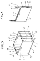
- the side walls 3, 5 are each formed of a succession of accordion panels, for example two 25, 26 as shown.
- the panels 25 and 26 are hinged together by an edge at 27 and on the lateral edge of the front walls 2 and rear 4 respectively by their other edge at 28, 29.
- the bottom 1, formed of slides 7, 8 generally supplemented by stiffening crosspieces, is articulated at 30 on the lower edge of one of the front or rear walls.
- the folding is done first by folding the side walls in an accordion ( Figure 9), so as to bring the front and rear walls to join, then by rotating the bottom upwards to bring it against the wall frontal.
- the front wall will include additional means of folding guidance along the slides 7, 8.
- the side walls 3, 5 are each formed by a hinged panel on one of the front or rear walls, for example the rear wall as shown.
- the front wall 1 is then articulated by its lower edge at 31 on the bottom 1, which is itself articulated on the rear wall 4 at 32.
- the folding is done by folding the side panels against the rear wall, then the front wall against the bottom ( Figure 12), and finally the bottom with the front wall folded against it against the rear wall. These folding movements are preferably done towards the inside of the container.
- the completely folded container has two exterior surfaces devoid of roughness.
- the folding movements could be provided towards the outside.
- the front wall is articulated on the bottom not directly, but by means of two lateral links 33.
- These links 33 are mounted for rotation by their ends on the lateral edge of the front panel on the one hand at 34 and in the middle of the lateral edge of the bottom at 35 on the other hand.
- the front panel can be tilted against these folded side panels by rotation of the rods 33 (FIG. 15), then bring the bottom panel against this assembly.
- the methods of locking the container in the folded and deployed position are known to those skilled in the art. For example, it could be snap mechanisms.
- the sliding panel can be blocked at the end of the release stroke, for example by end stops fixed on the slides.
- the panel may be able to be removed completely.
- the bottom panel 6 is smooth, or else it has parallel grooves or undulations, on one or both sides. Its upper surface can be slightly sloping to facilitate sliding when the container is full.
- the bottom panel 6 can simply slide along the slides, as shown. Alternatively, the sliding will be assisted by rollers or rollers.
- the plate could consist of parallel rollers.
- the sliding of the bottom panel is carried out from the front face of the container.
- the release of the bottom panel would be possible from the two front and rear faces of the container, each of these faces then having a recess allowing the bottom panel to be grasped.
- the bottom panel is provided in this case with a gripping means on each side.
- the container can be made, for example, of wood, fabric on a frame, or plastic, possibly an insulating material for transporting frozen goods.
- the bottom of the container is constituted by a frame carrying the side rails and the sliding bottom, the side wall being constituted by a strip of flexible fabric or a net comprising at its upper edge handles or a strap.
Landscapes
- Engineering & Computer Science (AREA)
- Mechanical Engineering (AREA)
- Rigid Containers With Two Or More Constituent Elements (AREA)
Applications Claiming Priority (2)
| Application Number | Priority Date | Filing Date | Title |
|---|---|---|---|
| FR9415807A FR2728542B1 (fr) | 1994-12-23 | 1994-12-23 | Recipient a fond amovible |
| FR9415807 | 1994-12-23 |
Publications (2)
| Publication Number | Publication Date |
|---|---|
| EP0720949A2 true EP0720949A2 (de) | 1996-07-10 |
| EP0720949A3 EP0720949A3 (de) | 1996-07-24 |
Family
ID=9470361
Family Applications (1)
| Application Number | Title | Priority Date | Filing Date |
|---|---|---|---|
| EP95480201A Withdrawn EP0720949A2 (de) | 1994-12-23 | 1995-12-22 | Behälter mit abnehmbarem Boden |
Country Status (2)
| Country | Link |
|---|---|
| EP (1) | EP0720949A2 (de) |
| FR (1) | FR2728542B1 (de) |
Cited By (9)
| Publication number | Priority date | Publication date | Assignee | Title |
|---|---|---|---|---|
| EP0900738A2 (de) * | 1997-08-07 | 1999-03-10 | Gold, Helmuth | Quaderförmiger Behälter |
| FR2780951A1 (fr) * | 1998-07-13 | 2000-01-14 | Michel Radot | Nouveau recipient a fond amovible |
| GB2356243A (en) * | 2000-07-25 | 2001-05-16 | Robert Waller | Thermally insulated container for a shopping trolley |
| DE102006005733A1 (de) * | 2006-02-07 | 2007-08-09 | Metallwarenfabrik Simon Gmbh | Präsentations-Behälter |
| GB2450930A (en) * | 2007-07-12 | 2009-01-14 | Linpac Materials Handling Ltd | A collapsible container with sliding base |
| US20170144310A1 (en) * | 2013-12-24 | 2017-05-25 | Ookuma Electronic Co., Ltd. | Injection conatiner storage box device and injection container picking system including the device |
| FR3055618A1 (fr) * | 2016-09-08 | 2018-03-09 | Guernet Compresseurs | Cage de protection pour le gonflage de pneumatique d'une roue de vehicule |
| CN109795782A (zh) * | 2018-12-27 | 2019-05-24 | 上海鸿研物流技术有限公司 | 容器 |
| WO2023131672A1 (fr) | 2022-01-07 | 2023-07-13 | Gp System | Boite de transfert d'articles dans un carton |
Citations (5)
| Publication number | Priority date | Publication date | Assignee | Title |
|---|---|---|---|---|
| US4158421A (en) * | 1978-01-30 | 1979-06-19 | Chi Hsu T | Foldable packing case |
| US4235331A (en) * | 1979-05-16 | 1980-11-25 | Bates Claude F Iii | Collapsible basket |
| WO1994005554A1 (de) * | 1992-09-10 | 1994-03-17 | Mauser-Werke Gmbh | Mehrweg-transportbehälter |
| DE9408039U1 (de) * | 1994-05-14 | 1994-07-14 | Rehau Ag & Co | Faltbarer Verpackungsbehälter |
| DE4403284A1 (de) * | 1993-01-30 | 1994-08-11 | Vaillant Joh Gmbh & Co | Verpackung für einen quaderförmigen Gegenstand |
-
1994
- 1994-12-23 FR FR9415807A patent/FR2728542B1/fr not_active Expired - Fee Related
-
1995
- 1995-12-22 EP EP95480201A patent/EP0720949A2/de not_active Withdrawn
Patent Citations (5)
| Publication number | Priority date | Publication date | Assignee | Title |
|---|---|---|---|---|
| US4158421A (en) * | 1978-01-30 | 1979-06-19 | Chi Hsu T | Foldable packing case |
| US4235331A (en) * | 1979-05-16 | 1980-11-25 | Bates Claude F Iii | Collapsible basket |
| WO1994005554A1 (de) * | 1992-09-10 | 1994-03-17 | Mauser-Werke Gmbh | Mehrweg-transportbehälter |
| DE4403284A1 (de) * | 1993-01-30 | 1994-08-11 | Vaillant Joh Gmbh & Co | Verpackung für einen quaderförmigen Gegenstand |
| DE9408039U1 (de) * | 1994-05-14 | 1994-07-14 | Rehau Ag & Co | Faltbarer Verpackungsbehälter |
Cited By (14)
| Publication number | Priority date | Publication date | Assignee | Title |
|---|---|---|---|---|
| EP0900738A2 (de) * | 1997-08-07 | 1999-03-10 | Gold, Helmuth | Quaderförmiger Behälter |
| EP0900738A3 (de) * | 1997-08-07 | 2001-02-21 | Gold, Helmuth | Quaderförmiger Behälter |
| FR2780951A1 (fr) * | 1998-07-13 | 2000-01-14 | Michel Radot | Nouveau recipient a fond amovible |
| GB2356243A (en) * | 2000-07-25 | 2001-05-16 | Robert Waller | Thermally insulated container for a shopping trolley |
| GB2356243B (en) * | 2000-07-25 | 2002-02-27 | Robert Waller | Thermally insulated container for a shopping trolley |
| DE102006005733A1 (de) * | 2006-02-07 | 2007-08-09 | Metallwarenfabrik Simon Gmbh | Präsentations-Behälter |
| GB2450930A (en) * | 2007-07-12 | 2009-01-14 | Linpac Materials Handling Ltd | A collapsible container with sliding base |
| GB2450930B (en) * | 2007-07-12 | 2011-12-21 | Linpac Allibert Ltd | Collapsible container |
| US20170144310A1 (en) * | 2013-12-24 | 2017-05-25 | Ookuma Electronic Co., Ltd. | Injection conatiner storage box device and injection container picking system including the device |
| US9682796B2 (en) * | 2013-12-24 | 2017-06-20 | Ookuma Electronic Co., Ltd. | Injection container storage box device and injection container picking system including the device |
| FR3055618A1 (fr) * | 2016-09-08 | 2018-03-09 | Guernet Compresseurs | Cage de protection pour le gonflage de pneumatique d'une roue de vehicule |
| CN109795782A (zh) * | 2018-12-27 | 2019-05-24 | 上海鸿研物流技术有限公司 | 容器 |
| WO2023131672A1 (fr) | 2022-01-07 | 2023-07-13 | Gp System | Boite de transfert d'articles dans un carton |
| FR3131736A1 (fr) | 2022-01-07 | 2023-07-14 | Gp System | Boite de transfert d’articles dans un carton |
Also Published As
| Publication number | Publication date |
|---|---|
| FR2728542B1 (fr) | 1997-03-28 |
| EP0720949A3 (de) | 1996-07-24 |
| FR2728542A1 (fr) | 1996-06-28 |
Similar Documents
| Publication | Publication Date | Title |
|---|---|---|
| EP0337043B1 (de) | Einkaufswagen mit schwenkbarem Korb | |
| EP0206872B1 (de) | Zusammenklappbarer Wagen zum Transport und/oder zur Lagerung von Gegenständen oder Schüttgut | |
| EP2897485A1 (de) | Verbesserter koffer und satz von koffern | |
| EP0720949A2 (de) | Behälter mit abnehmbarem Boden | |
| FR2569151A1 (fr) | Chariot de type " caddie " a recipients amovibles | |
| WO1992015191A1 (fr) | Chariot reglable de transport a roues escamotables a charger plein dans tout coffre automobile sans operation mecanique | |
| WO1999041154A1 (fr) | Conteneur repliable pour le stockage de panneaux d'habillage de portieres d'automobiles | |
| FR2708898A1 (fr) | Chariot destiné à la manutention d'objets divers. | |
| FR2770479A1 (fr) | Chariot pliable | |
| EP0349423B1 (de) | Stapelbarer Einkaufswagen mit einziehbarer Ablage unter dessen Korb | |
| FR2747634A1 (fr) | Chariot individuel de transport de marchandises et contenant amovible destine a etre utilise avec un tel chariot | |
| FR2573378A1 (fr) | Dispositif transporteur de charges pour magasins notamment | |
| WO2006064045A1 (fr) | Sac de transport de marchandises | |
| FR2579158A1 (fr) | Chariot a provisions pliable et retractable utilisable en grandes surfaces et pour les marches | |
| FR2550074A1 (fr) | Perfectionnements aux dispositifs pour le transport des marchandises acquises dans les magasins a libre-service | |
| FR3063964A1 (fr) | Chariot de courses pour poussette | |
| FR3066747A1 (fr) | Chariot a provisions, vehicule, ensemble et procede de chargement associes | |
| CH659219A5 (en) | Wheeled trolley with basket | |
| WO2015145065A1 (fr) | Chariot universel | |
| FR3084869A1 (fr) | Chariot multifonctionnel | |
| EP2221231B1 (de) | Transporteinheit, die einen Rollwagen und mindestens zwei entsprechend angepasste Behälter umfasst | |
| WO2011124769A1 (fr) | Chariot modulaire encastrable | |
| FR2795709A1 (fr) | Module de stockage d'articles a elements de reception suspendus | |
| FR2833550A1 (fr) | Chariot de transport manoeuvre a la main | |
| EP2097306A1 (de) | Zimmerservicewagen für hotels |
Legal Events
| Date | Code | Title | Description |
|---|---|---|---|
| PUAI | Public reference made under article 153(3) epc to a published international application that has entered the european phase |
Free format text: ORIGINAL CODE: 0009012 |
|
| PUAL | Search report despatched |
Free format text: ORIGINAL CODE: 0009013 |
|
| AK | Designated contracting states |
Kind code of ref document: A2 Designated state(s): AT BE CH DE DK ES FR GB GR IE IT LI LU MC NL PT SE |
|
| AK | Designated contracting states |
Kind code of ref document: A3 Designated state(s): AT BE CH DE DK ES FR GB GR IE IT LI LU MC NL PT SE |
|
| 17P | Request for examination filed |
Effective date: 19970124 |
|
| 17Q | First examination report despatched |
Effective date: 19970807 |
|
| STAA | Information on the status of an ep patent application or granted ep patent |
Free format text: STATUS: THE APPLICATION IS DEEMED TO BE WITHDRAWN |
|
| 18D | Application deemed to be withdrawn |
Effective date: 20000703 |