EP0720873A2 - Extrudierungs-Beschichtungsverfahren - Google Patents
Extrudierungs-Beschichtungsverfahren Download PDFInfo
- Publication number
- EP0720873A2 EP0720873A2 EP96300063A EP96300063A EP0720873A2 EP 0720873 A2 EP0720873 A2 EP 0720873A2 EP 96300063 A EP96300063 A EP 96300063A EP 96300063 A EP96300063 A EP 96300063A EP 0720873 A2 EP0720873 A2 EP 0720873A2
- Authority
- EP
- European Patent Office
- Prior art keywords
- coating composition
- coating
- die
- extrusion die
- extrusion
- Prior art date
- Legal status (The legal status is an assumption and is not a legal conclusion. Google has not performed a legal analysis and makes no representation as to the accuracy of the status listed.)
- Granted
Links
Images

Classifications
-
- B—PERFORMING OPERATIONS; TRANSPORTING
- B05—SPRAYING OR ATOMISING IN GENERAL; APPLYING FLUENT MATERIALS TO SURFACES, IN GENERAL
- B05D—PROCESSES FOR APPLYING FLUENT MATERIALS TO SURFACES, IN GENERAL
- B05D1/00—Processes for applying liquids or other fluent materials
- B05D1/26—Processes for applying liquids or other fluent materials performed by applying the liquid or other fluent material from an outlet device in contact with, or almost in contact with, the surface
- B05D1/265—Extrusion coatings
-
- B—PERFORMING OPERATIONS; TRANSPORTING
- B05—SPRAYING OR ATOMISING IN GENERAL; APPLYING FLUENT MATERIALS TO SURFACES, IN GENERAL
- B05C—APPARATUS FOR APPLYING FLUENT MATERIALS TO SURFACES, IN GENERAL
- B05C5/00—Apparatus in which liquid or other fluent material is projected, poured or allowed to flow on to the surface of the work
- B05C5/02—Apparatus in which liquid or other fluent material is projected, poured or allowed to flow on to the surface of the work the liquid or other fluent material being discharged through an outlet orifice by pressure, e.g. from an outlet device in contact or almost in contact, with the work
- B05C5/0254—Coating heads with slot-shaped outlet
Definitions
- This invention relates to a process for applying a coating of pigment particles in a film forming binder by extrusion coating techniques.
- the extrusion die For fabrication of web type, flexible electrophotographic imaging members, the extrusion die must lay down very thin coatings meeting extremely precise, critical tolerances in the single or double digit micrometer ranges. Moreover, a plurality of dies may be needed to lay down up to three extruded coatings conventionally employed for flexible electrophotographic imaging members.
- the flexible electrophotographic imaging members may also comprise additional coatings applied by non-extrusion coating techniques so that the finished electrophotographic imaging member can contain as many as 5 different coatings.
- the extrusion die usually comprises spaced walls, each having a surface facing each other.
- a coating composition is supplied by a reservoir through an inlet to a manifold that feeds the coating composition to one side of the passageway and the coating composition travels through the passageway to an exit slot on the side of the passageway opposite the reservoir.
- Dams are provided at opposite ends of the passageway to confine the coating composition within the passageway as the coating travels from the reservoir to the exit slot.
- a process for forming a coating from a coating composition comprising pigment particles dispersed in a solution of a film forming binder dissolved in a fugitive liquid carrier, maintaining the coating composition in a flow field under average shear conditions at least about 10 reciprocal seconds with a most preferred having a minimum average shear rate of at least about 50 reciprocal seconds while transporting the coating composition through an inlet of an extrusion die, through a manifold of the die, through an extrusion slot of the extrusion die and onto a substrate to form a coating layer on the substrate, and rapidly removing the fugitive liquid from the coating while maintaining the coating composition in the coating layer in an undisturbed condition until the coating solidifies.
- This process may be employed to coat the surface of support members of various configurations including webs, sheets, plates, drums, and the like.
- the support member may be flexible, rigid, uncoated, precoated, as desired.
- the support members may comprise a single layer or be made up of multiple layers.
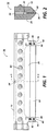
- Die assembly 10 comprises a die body 12 equipped with clamping flanges 14 and 16. Die body 12 comprises and upper body 18 and lower body 20 which are spaced apart to form a flat narrow passageway 22 (see FIG. 2).
- Passageway 22 is fed a coating composition which enters die body 12 through inlet 24 and is transported through manifold 25 and through passageway 22 to exit slot 26 through which the coating composition is extruded as a ribbon-like stream onto a moving web substrate (not shown).
- the width, thickness, and the like of the ribbon-like stream can be varied in accordance with factors such as the viscosity of the coating composition, thickness of the coating desired, and width of the web substrate on which the coating composition is applied, and the like.
- End dams 30 and 32 are secured to the ends of upper body 18 and lower body 20 of die body 12 to confine the coating composition within the ends of die body 12.
- the length of passageway 22 should be sufficiently long to also ensure laminar (or streamline) flow.
- Control of the distance of exit slot 26 from the substrate to be coated enables the coating composition to bridge the gap between the exit slot 26 and the moving substrate depending upon the viscosity and rate of flow of the coating composition.
- Clamping flanges 14 and 16 contain threaded holes into which set screws 40 and 42 are screwed to secure end dams 30 and 32 against the open ends of die body 12. Any suitable means such as screws 43, bolts, studs, or clamps (not shown) or the like, may be uti lized to fasten upper lip 18 and lower lip 20 together.
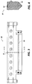
- FIGS. 3 and 4 a die assembly embodiment of this invention 50 is shown. It is similar in shape to the die assembly shown in FIGS 1 and 2 except for the size and shape of the inlet 52, manifold 54 and passageway 56.
- the cross sectional area of the inlet 52 has been markedly reduced.
- Manifold 54 has a very small circular cross-sectional shape instead of the large tear drop cross-sectional shape of the manifold 25 shown in FIG. 2. Reduction of the cross-sectional area of the inlet 52 and manifold 54 also reduces the residence time of the coating material in the extrusion die. These changes prevent the flocculation of pigment particles dispersed in a liquid carrier.
- particles of benzimidazole perylene tends to flocculate from dispersions at low shear conditions. It should be noted, however, that some dispersed particulate materials do not regulate or flocculate at low shear conditions.
- An example of particulate materials that form relatively stable dispersions that do not flocculate at low shear conditions include, for example, inorganic trigonal selenium particles.
- FIG. 5 illustrates a conventional arrangement where a coating composition is supplied from a reservoir (not shown) through line 60 to a conventional pump 62 or other suitable well known means such as a gas pressure system (not shown) which feeds the coating composition under pressure through a feed line 64 to the inlet 66 of the die body 68.
- a conventional pump 62 or other suitable well known means such as a gas pressure system (not shown) which feeds the coating composition under pressure through a feed line 64 to the inlet 66 of the die body 68.
- FIG. 6 illustrates a similar arrangement except that a needle valve 70 is placed in the feed line 64 between pump 62 and inlet 66 of the die body 68.
- the needle valve is adjusted to obtain a pressure drop in the flowing coating composition as it passes through needle valve 70.
- the imposed pressure drop imparts energy to the coating compostion and further breaks-up any flocculation.
- Needle valve 70 is adjustable to compensate for different conditions such a change in coating composition viscosity.
- the mixing value is operated with a pressure drop such that the shear rate in the value is greater than 100 sec -1 .
- any suitable rigid material may be utilized for the main die body.
- Typical rigid materials include, for example, stainless steel, chrome plated steel, ceramics, or any other metal or plastic capable of maintaining precise machining tolerances.
- Stainless steel and plated steel having a nickel plated intermediate coating and a chrome plated outer coating are preferred because of their long wear characteristics and capability of maintaining precise machining tolerances.
- the main die body may comprise separate top and bottom sections. To achieve the extremely precise coating thickness profiles and exceptional surface quality requirements desired for electrophotographic imaging member coatings, the finish grinding of the die should be accomplished consistently under high tolerance constraints across the entire die width, e.g. widths as high as 155 (60 inches).
- any suitable coating composition may be applied to a substrate with the extrusion die of this invention.
- the coating composition comprises pigment particles dispersed in a solution of a film forming binder dissolved in a fugitive liquid carrier.
- Any suitable liquid carrier may be utilized.
- a liquid carrier is a solvent for the film forming binder utilized in the coating mixture.
- the fugitive liquid carrier may be a solvent which dissolves the film forming polymer.
- Typical solvents or liquid carriers include, for example, methylene chloride, tetrahydrofuran, toluene, methyl ethyl ketone, isopropanol, methanol, cyclohexanone, heptane, other chlorinated solvents, water, and the like.
- Any suitable film forming polymer may be used.
- Typical film forming polymers include, for example, polycarbonates, polyesters, polyvinylbutyrals, VMCH and the like. Satisfactory results are achieved when the film forming binder is present in the final coating in an amount between about 10 and about 90 volume percent based on the total volume of the dried coating. Preferably, between about 30 percent and about 80 percent by volume of the film forming binder is present in the dried coating.
- any suitable organic pigment particles may be used in the coating composition.
- Typical organic pigment particles include, for example the phthalocyaninies: hydroxy-gallium, vanadyl, titanyl, X-form metal free, etc. or the perylenes such as benzimidazole perylene and the like. Whereas satisfactory results are achieved when average pigment particle size is less than about 1 micrometer. Preferably, the average pigment particle size is less than about 0.5 micrometers.
- the pigment concentration in the coating compositions utilized in the process of this invention is between about 20 percent and about 80 percent by volume based on the total volume of the coating composition.
- flocculation is avoided in the flowing mixture while it passes through the die inlet, die manifold, die slot and while it dries as a coating on coated substrate by maintaining the coating composition in a high shear flow field with and average shear rate of at least 10 reciprocal seconds with average shear rates above 50 reciprocal seconds preferred.
- the average shear rate at entrance to a die slot with a prior art is about 2 reciprocal seconds or less.
- the typical average shear rate at the entrance to a die slot in the process of this invention is 120 reciprocal seconds.
- the flow history of the dispersion utilized in the process of this invention has a shear rate at least about 50 reciprocal seconds.
- Shear thinning a non newtonian condition
- Shear can be measured with the aid of a rheometer.
- rheometers comprise a cup containing the dispersion to be measured and a rotating cylinder immersed in the dispersion.
- flocculation occurs, clumps of pigment material are visible to the naked eye.
- the clumps have a three dimensional network structure whereas non-newtonian dispersions have a two dimensional structure.
- Shear thinning dispersions possess a yield point.
- the dispersions are subjected to sufficient shear thinning to maintain the dispersion above the yield point.
- the size of the clumps prior to exceeding the yield point have an average size of at about 200 micrometers or greater whereas the average particle size and coating compositions maintained above the yield point have an average particle size of about 10 micrometers or less.
- the coating compositions utilized in the process of this invention are also subjected to a pressure drop across a mixing valve of at least 10 psi.
- a typical inlet channel has the cross-sectional area of less than about 0.5 millimeters. Typical inlet channel lengths range from several millimeters to many centimeters long.
- the coating dispersion of this invention is subjected to intense shearing through the extrusion die to the point where the dispersion emerges from the extrusion nozzle.
- the coating formed by the extrusion process is maintained in an undisturbed condition while the solvent is removed. Because of the power law index and yield point, the particles and coatings freshly formed by the process of this invention do not associate and form agglomerates because the liquid carrier is removed before such agglomeration can occur. Thus, it is also important that the applied coating dry prior to formation of clumps.
- the use of a highly volatile fugitive liquid carrier facilitates avoidance of clumping.
- a "streaky/mottle" band pattern can occasionally form in the coating in the region immediately opposite the point where the inlet channel joins the die manifold.
- a means to create a high pressure drop positioned between the coating dispersion supply reservoir and the inlet channel into die manifold is desirable. Any suitable means to create a high pressure drop over a short distance and an average shear rate of at least about 100 reciprocal seconds may be utilized. Typical means to create a pressure drop include, for example, needle valve and orifice plate, ball valve, jet nozzle , short capillary tube, and the like.
- Needle valves are particularly preferred because they are adjustable to accommodate changes in concentration of the pigment, distance, coating mixture of viscosity and the like. Devices that create a pressure drop are also associated with high average shear rates. However, a static mixer such as employed in US-A 5,273,583 does not produce an average shear rate of greater than about 20 reciprocal seconds.
- narrow die passageway and exit slot height generally depends upon factors such as the fluid viscosity, flow rate, distance to the surface of the support member, relative movement between the die and the substrate and the thickness of the coating desired. Generally, satisfactory results may be achieved with narrow passageway and exit slot heights between about 75 micrometers and about 400 micrometers. Good coating results have been achieved with slot heights between about 100 micrometers and about 200 micrometers. Optimum control of coating uniformity and edge to edge contact are achieved with slot heights between about 125 micrometers and about 150 micrometers.
- the roof, sides and floor of the narrow die passageway should preferably be parallel and smooth to ensure achievement of laminar flow.
- the gap distance between the die outer lip surface adjacent to the exit slot and the surface of the substrate to be coated depends upon variables such as viscosity of the coating material, the velocity of the coating material and the angle of the narrow extrusion passageway relative to the surface of the support member. Generally speaking, a smaller gap is desirable for lower flow rates. Regardless of the technique employed, the flow rate and distance should be regulated to avoid splashing, dripping, puddling and doctoring of the coating material.
- the flow velocities or flow rate per unit width of the narrow die passageway for the ribbon-like stream of coating material should be sufficient to fill the die to prevent dribbling and to bridge the gap as a continuous stream moves to the surface of the substrate.
- the flow velocity should not exceed the point where non-uniform coating thicknesses are obtained due to splashing or puddling of the coating composition. Varying the die to substrate surface distance and the relative die to support member surface speed will help compensate for high or low coating composition flow velocities.
- the coating technique of this invention can accommodate an unexpectedly wide range of coating compositions viscosities from viscosities comparable to that of water to viscosities of molten waxes and molten thermoplastic resins.
- lower coating composition viscosities tend to form thinner wet coatings whereas coating compositions having high viscosities tend to form thicker wet coatings.
- wet coating thickness will form thin dry coatings when the coating compositions employed are in the form of solutions, dispersions or emulsions.
- the pressures utilized to extrude the coating compositions through the narrow die passageway depends upon the size of the passageway and viscosity of the coating composition.
- any suitable temperature may be employed in the coating deposition process. Generally, ambient temperatures are preferred for deposition of solution coatings. However, higher temperatures may be necessary for depositing coatings such as hot melt coatings.
- a coating composition was prepared containing about 280-grams of an organic photoconductive perylene pigment having a particle size of about 0.2 micrometer, about 320 grams of polycarbonate binder resin, and about 9400 grams of a volatile solvent. This composition had a viscosity of about 105 cp and was applied by means of an extrusion die (similar to the die illustrated in FIGS. 1 and 2) to a metalized polyethylene terephthalate film coated with a polyester coating.
- the extrusion die design incorporated an inlet diameter of 0.5 inch (12.7 millimeters), a manifold diameter of 0.71 inch (18 millimeters), and passageway height of 0.005 inch ( 0.127 millimeters).
- the geometric average shear rate was 2 sec -1 or less, the residency time of the coating composition was approximately 16 seconds and the flow rate of 200 cc/min in the extrusion die.
- the film was transported beneath the die assembly at about 21 meters per minute.
- the length, width, and height of the narrow extrusion passageway in the die was about 28 mm, 410 mm, and 0.127 millimeters respectively.
- the deposited coating was dried in a multizone dryer with a maximum temperature of 143 °C.
- the deposited dried coating exhibited a visible non-uniform mottle pattern resembling brush marks as well as streaks and dark spots.
- Example I The procedures described in Example I were repeated except that a different die design was employed (similar to the die illustrated in FIGS. 3 and 4).
- the extrusion die design incorporated an inlet diameter of 0.19 inch, a manifold diameter of 0.1875 inch (4.8 millimeters), and passageway height of 005 inch (0.127 millimeters).
- the geometric average shear rate at the inlet to the manifold was 100 sec -1 or higher, the residency time of the coating composition was 2.6 seconds and the flow rate was 200 cc/min in the extrusion die.
- the film was transported beneath the die assembly at about 21 meters per minute.
- the length, width, and height of the narrow extrusion passageway in the die was about 28 mm, 410 mm, and 0.127 millimeters respectively.
- the deposited coating was dried in a multizone dryer at a maximum temperature of 143 °C.
- the deposited dried coating exhibited no visible brush marks, streaks or dark spots except at the center of the coating opposite the die inlet. At the center of the coating, a "streaky/mottle band, 5 - 10 cm wide was observed. This defect was resolved as in example III.
- Example II The procedures described in Example II were repeated except that a needle valve was installed in the feed line at the inlet of the die.
- the needle valve was adjusted to achieve a pressure drop across the valve of 10 psig.
- the deposited dried coating exhibited neither visible brush marks, streaks or dark spots, nor a "streaky/mottle band immediately opposite the inlet to the die.
- Example 1 The procedures described in example 1 where repeated with a coating composition containing about 236 grams of an organic photoconductive pthalocyanine pigment having a particle size of about 0.2 micrometers, about 266 grams of polycarbonate binder resin, and about 9911 grams of a volatile solvent.
- This composition had a viscosity of about 12 cp and was applied by means of an extrusion die (similar to the die illustrated in FIGS. 1 and 2) to a metalized polyethylene terephthalate film coated with a polyester coating.
- the extrusion die design incorporated an inlet diameter of 0.5 inch ( 12.7 millimeters), a manifold diameter of 0.71 inch (18 millimeters), and passageway height of 0.005 inch (0.127 millimeters).
- the geometric average shear rate was 2 sec -1 or less, the residency time of the coating composition was approximately 16 seconds and the flow rate of 200 cc/min in the extrusion die.
- the film was transported beneath the die assembly at about 21 meters per minute.
- the length, width, and height of the narrow extrusion passageway in the die was about 28 mm, 410 mm, and 0.127 millimeters respectively.
- the deposited coating was dried in a multizone dryer with a maximum temperature of 143 °C.
- the deposited dried coating exhibited a visible non-uniform mottle pattern resembling brush marks as well as streaks and dark spots.
- Example IV The procedures described in Example IV were repeated except that the die design from Example II was employed (similar to the die illustrated in FIGS. 3 and 4).
- the film was transported beneath the die assembly at about 21 meters per minute.
- the length, width, and height of the narrow extrusion passageway in the die was about 28 mm, 410 mm, and 0.127 millimeters respectively.
- the deposited coating was dried in a multizone dryer at a maximum temperature of 143 °C.
- the deposited dried coating exhibited no visible brush marks, streaks or dark spots except at the center of the coating opposite the die inlet. At the center of the coating, a "streaky/mottle band, 5 - 10 cm wide was observed. This defect was resolved as in Example III.
- Example V The procedures described in Example V were repeated except that a needle valve was installed in the feed line at the inlet of the die.
- the needle valve was adjusted to achieve a pressure drop across the valve of 10 psig.
- the deposited dried coating exhibited no neither visible brush marks, streaks or dark spots, nor a "streaky/mottle" band immediately opposite the inlet to the die.
Landscapes
- Application Of Or Painting With Fluid Materials (AREA)
- Photoreceptors In Electrophotography (AREA)
- Paints Or Removers (AREA)
- Coating Apparatus (AREA)
Applications Claiming Priority (2)
| Application Number | Priority Date | Filing Date | Title |
|---|---|---|---|
| US08/368,129 US5516557A (en) | 1995-01-03 | 1995-01-03 | Method for applying a flocculating coating composition including maintaining turbulent flow conditions during extrusion |
| US368129 | 1995-01-03 |
Publications (3)
| Publication Number | Publication Date |
|---|---|
| EP0720873A2 true EP0720873A2 (de) | 1996-07-10 |
| EP0720873A3 EP0720873A3 (de) | 1998-12-16 |
| EP0720873B1 EP0720873B1 (de) | 2002-05-02 |
Family
ID=23449962
Family Applications (1)
| Application Number | Title | Priority Date | Filing Date |
|---|---|---|---|
| EP96300063A Expired - Lifetime EP0720873B1 (de) | 1995-01-03 | 1996-01-03 | Extrudierungs-Beschichtungsverfahren |
Country Status (4)
| Country | Link |
|---|---|
| US (1) | US5516557A (de) |
| EP (1) | EP0720873B1 (de) |
| JP (1) | JP3810839B2 (de) |
| DE (1) | DE69620922T2 (de) |
Families Citing this family (7)
| Publication number | Priority date | Publication date | Assignee | Title |
|---|---|---|---|---|
| EP0825241B1 (de) * | 1996-08-16 | 2003-03-26 | Nippon Telegraph And Telephone Corporation | Wasserabweisende Beschichtung, Verfahren zu ihrer Herstellung, sowie deren Verwendung in Beschichtungen und für beschichtete Gegenstände |
| US7559990B2 (en) * | 1998-05-19 | 2009-07-14 | Eugene A Pankake | Coating apparatus and method |
| US6057000A (en) * | 1998-10-29 | 2000-05-02 | Xerox Corporation | Extrusion coating process |
| US20090295098A1 (en) * | 1999-05-18 | 2009-12-03 | Pankake Eugene A | Coating apparatus and method |
| US20030215581A1 (en) * | 2002-05-20 | 2003-11-20 | Eastman Kodak Company | Polycarbonate films prepared by coating methods |
| US20060024445A1 (en) * | 2004-07-28 | 2006-02-02 | Xerox Corporation | Extrusion coating system |
| JP2015178050A (ja) * | 2014-03-18 | 2015-10-08 | 日東電工株式会社 | 塗工装置及び塗工膜の製造方法 |
Citations (2)
| Publication number | Priority date | Publication date | Assignee | Title |
|---|---|---|---|---|
| US4521457A (en) | 1982-09-21 | 1985-06-04 | Xerox Corporation | Simultaneous formation and deposition of multiple ribbon-like streams |
| US5273583A (en) | 1990-07-02 | 1993-12-28 | Xerox Corporation | Fabrication of electrophotographic imaging members |
Family Cites Families (3)
| Publication number | Priority date | Publication date | Assignee | Title |
|---|---|---|---|---|
| US3227136A (en) * | 1961-10-26 | 1966-01-04 | Eastman Kodak Co | Extrusion coating apparatus |
| US4038442A (en) * | 1975-09-16 | 1977-07-26 | Fuji Photo Film Co., Ltd. | Method for coating |
| US5149612A (en) * | 1990-07-02 | 1992-09-22 | Xerox Corporation | Fabrication of electrophotographic imaging members |
-
1995
- 1995-01-03 US US08/368,129 patent/US5516557A/en not_active Expired - Lifetime
- 1995-12-26 JP JP33888495A patent/JP3810839B2/ja not_active Expired - Fee Related
-
1996
- 1996-01-03 DE DE69620922T patent/DE69620922T2/de not_active Expired - Fee Related
- 1996-01-03 EP EP96300063A patent/EP0720873B1/de not_active Expired - Lifetime
Patent Citations (2)
| Publication number | Priority date | Publication date | Assignee | Title |
|---|---|---|---|---|
| US4521457A (en) | 1982-09-21 | 1985-06-04 | Xerox Corporation | Simultaneous formation and deposition of multiple ribbon-like streams |
| US5273583A (en) | 1990-07-02 | 1993-12-28 | Xerox Corporation | Fabrication of electrophotographic imaging members |
Also Published As
| Publication number | Publication date |
|---|---|
| EP0720873A3 (de) | 1998-12-16 |
| JPH08229496A (ja) | 1996-09-10 |
| DE69620922D1 (de) | 2002-06-06 |
| DE69620922T2 (de) | 2002-08-29 |
| JP3810839B2 (ja) | 2006-08-16 |
| US5516557A (en) | 1996-05-14 |
| EP0720873B1 (de) | 2002-05-02 |
Similar Documents
| Publication | Publication Date | Title |
|---|---|---|
| US4681062A (en) | Coating apparatus | |
| EP0807279B1 (de) | Methode und vorrichtung zum auftragen einer dünnen,flüssigen,gestreiften beschichtung | |
| JP2581975B2 (ja) | 塗布装置 | |
| US6057000A (en) | Extrusion coating process | |
| US4871593A (en) | Method of streakless application of thin controlled fluid coatings and slot nozzle - roller coater applicator apparatus therefor | |
| DE69530999T2 (de) | Verfahren und vorrichtung zur beschichtung von substraten durch verwendung eines luftmessers | |
| US4907530A (en) | Apparatus for applying a liquid to a support | |
| JPH0217971A (ja) | 塗布方法 | |
| EP1857189B1 (de) | Auftragsvorrichtung, auftragsverfahren und verfahren zur herstellung einer bahn mit einem überzugsfilm | |
| JPH01194966A (ja) | 移動基体ヘコーティング物質を適用し且つ添加するための方法及び装置 | |
| EP0706833B1 (de) | Kontinuierliches lackierverfahren | |
| US4324816A (en) | Method for forming a stripe by extrusion coating | |
| US5516557A (en) | Method for applying a flocculating coating composition including maintaining turbulent flow conditions during extrusion | |
| JP2601367B2 (ja) | 塗布方法 | |
| EP0784516A1 (de) | Verfahren zurm rakel-beschichten unter einsteigender spannung | |
| US5614260A (en) | Extrusion system with slide dies | |
| EP0699485B1 (de) | Verfahren und Vorrichtung zum Beschichten einer laufenden Filmbahn | |
| JPS6040904B2 (ja) | 反応性混合物の連続塗布装置 | |
| KR100286594B1 (ko) | 도포방법 및 도포장치 | |
| JPH0550004A (ja) | 塗布液の塗布方法および塗布装置 | |
| EP0679497B1 (de) | Extrusiondüse mit geglühter Seitenwand,ihr Herstellungsverfahren, Beschichtungsverfahren | |
| US6666946B2 (en) | Method of high speed coating pigment-containing liquid coating materials | |
| JPH06226195A (ja) | カ−テンフロ−塗装方法 | |
| CS199113B1 (cs) | Zařízení k plynulému nanášení vrstev roztoků nebo disperzí polymerů na pohybující se podložku | |
| JPH04274436A (ja) | 感光体の製造方法およびその装置 |
Legal Events
| Date | Code | Title | Description |
|---|---|---|---|
| PUAI | Public reference made under article 153(3) epc to a published international application that has entered the european phase |
Free format text: ORIGINAL CODE: 0009012 |
|
| AK | Designated contracting states |
Kind code of ref document: A2 Designated state(s): DE FR GB |
|
| PUAL | Search report despatched |
Free format text: ORIGINAL CODE: 0009013 |
|
| AK | Designated contracting states |
Kind code of ref document: A3 Designated state(s): DE FR GB |
|
| 17P | Request for examination filed |
Effective date: 19990616 |
|
| 17Q | First examination report despatched |
Effective date: 20000419 |
|
| GRAG | Despatch of communication of intention to grant |
Free format text: ORIGINAL CODE: EPIDOS AGRA |
|
| GRAG | Despatch of communication of intention to grant |
Free format text: ORIGINAL CODE: EPIDOS AGRA |
|
| GRAH | Despatch of communication of intention to grant a patent |
Free format text: ORIGINAL CODE: EPIDOS IGRA |
|
| GRAH | Despatch of communication of intention to grant a patent |
Free format text: ORIGINAL CODE: EPIDOS IGRA |
|
| REG | Reference to a national code |
Ref country code: GB Ref legal event code: IF02 |
|
| GRAA | (expected) grant |
Free format text: ORIGINAL CODE: 0009210 |
|
| STAA | Information on the status of an ep patent application or granted ep patent |
Free format text: STATUS: THE PATENT HAS BEEN GRANTED |
|
| AK | Designated contracting states |
Kind code of ref document: B1 Designated state(s): DE FR GB |
|
| REG | Reference to a national code |
Ref country code: GB Ref legal event code: FG4D |
|
| REF | Corresponds to: |
Ref document number: 69620922 Country of ref document: DE Date of ref document: 20020606 |
|
| ET | Fr: translation filed | ||
| PLBE | No opposition filed within time limit |
Free format text: ORIGINAL CODE: 0009261 |
|
| 26N | No opposition filed |
Effective date: 20030204 |
|
| REG | Reference to a national code |
Ref country code: GB Ref legal event code: 746 Effective date: 20041130 |
|
| REG | Reference to a national code |
Ref country code: FR Ref legal event code: D6 |
|
| PGFP | Annual fee paid to national office [announced via postgrant information from national office to epo] |
Ref country code: DE Payment date: 20061229 Year of fee payment: 12 |
|
| PGFP | Annual fee paid to national office [announced via postgrant information from national office to epo] |
Ref country code: GB Payment date: 20070103 Year of fee payment: 12 |
|
| PGFP | Annual fee paid to national office [announced via postgrant information from national office to epo] |
Ref country code: FR Payment date: 20070109 Year of fee payment: 12 |
|
| GBPC | Gb: european patent ceased through non-payment of renewal fee |
Effective date: 20080103 |
|
| PG25 | Lapsed in a contracting state [announced via postgrant information from national office to epo] |
Ref country code: DE Free format text: LAPSE BECAUSE OF NON-PAYMENT OF DUE FEES Effective date: 20080801 |
|
| REG | Reference to a national code |
Ref country code: FR Ref legal event code: ST Effective date: 20081029 |
|
| PG25 | Lapsed in a contracting state [announced via postgrant information from national office to epo] |
Ref country code: GB Free format text: LAPSE BECAUSE OF NON-PAYMENT OF DUE FEES Effective date: 20080103 |
|
| PG25 | Lapsed in a contracting state [announced via postgrant information from national office to epo] |
Ref country code: FR Free format text: LAPSE BECAUSE OF NON-PAYMENT OF DUE FEES Effective date: 20080131 |