EP0720343B1 - Bildverarbeitungsgerät - Google Patents
Bildverarbeitungsgerät Download PDFInfo
- Publication number
- EP0720343B1 EP0720343B1 EP95120587A EP95120587A EP0720343B1 EP 0720343 B1 EP0720343 B1 EP 0720343B1 EP 95120587 A EP95120587 A EP 95120587A EP 95120587 A EP95120587 A EP 95120587A EP 0720343 B1 EP0720343 B1 EP 0720343B1
- Authority
- EP
- European Patent Office
- Prior art keywords
- recording
- sheet
- original
- unit
- recording device
- Prior art date
- Legal status (The legal status is an assumption and is not a legal conclusion. Google has not performed a legal analysis and makes no representation as to the accuracy of the status listed.)
- Expired - Lifetime
Links
Images


Classifications
-
- H—ELECTRICITY
- H04—ELECTRIC COMMUNICATION TECHNIQUE
- H04N—PICTORIAL COMMUNICATION, e.g. TELEVISION
- H04N1/00—Scanning, transmission or reproduction of documents or the like, e.g. facsimile transmission; Details thereof
- H04N1/00681—Detecting the presence, position or size of a sheet or correcting its position before scanning
Definitions
- the present invention relates to an image processing apparatus and, more particularly, to an image processing apparatus which is constituted by integrating a recording device (to be referred to as a printer hereinafter) complying with a Bicentronics interface standard, and an image reading device (to be referred to as a scanner hereinafter).
- the new standard has a basic conception in that bidirectional data exchange is attained between a host computer and peripheral devices instead of the conventional conception in that data is output from the host side using signal lines such as GND, Vcc, strobe, acknowledge, busy lines, and the like, and an 8-bit (1-byte) data signal line.
- the new standard is a promising one since it is an interface standard which can maximally exhibit its advantage, e.g., can effectively utilize recent processors that have increasingly improved their processing power.
- a color original image is read using a scanner, and the scanned image is temporarily stored in an image memory unit to obtain a soft copy on a computer display. Thereafter, the soft copy is subjected to desired image processing, and the processed copy is output to a color printer, thereby obtaining a desired color hard copy.
- a general user normally sets a mouse, a keyboard, and the like on the desk in addition to the host computer, scanner, printer, and the like.
- the host computer and the scanner require large setting spaces since a sheet path for at least A4-size recording sheets and original sheets must be assured, and they can no longer set on a single desk.
- a setting rack having some shelves is required.
- an ink cartridge When, e.g., an ink-jet printer is used as the recording device, an ink cartridge must be appropriately exchanged. Since ink in the ink cartridge is consumed by recording operations, various kinds of alarm means are provided to the printer side so as to inform a user of the use-up state of the ink. Nonetheless, ink is often used up during a print operation. When the cartridge is exchanged at that time, a user discards the sheet in the print operation, and restarts the print operation from the beginning. Alternatively, after the carriage of the printer is moved to the standby position, the exchange cover of the printer is opened, a new cartridge is set, and thereafter, the print operation is restarted.
- An auxiliary ink cartridge may be lost and cannot be found or may be out of stock unless a user keeps a new one in a predetermined place. As a result, the print operation cannot often be restarted.
- GB-A-2 238 758 shows an image processing apparatus which integrates a recording device which records on a recording sheet by recording means, and an image reading device which reads an original sheet by reading means, wherein the recording device is provided within a housing and the image reading device is provided above the recording device.
- a control circuit board must be provided and can be connected to a host computer which is provided separately.
- the recording device has recording sheet handling means which realizes entering of the recording sheet.
- the reading device has original sheet handling means which realizes entering the original sheet.
- EP-A-0 602 667 A1 shows an image processing apparatus which integrates a recording device which records on a recording sheet by recording means.
- a housing further houses a control circuit board.
- the control circuit board is connected to a host computer which is provided separately via a Bicentronics-standard interface cable.
- GB-A-2 276 510 shows an image processing apparatus which integrates a recording device which records on a recording sheet by recording means, and an image reading device which reads an original sheet by reading means, wherein the recording device is provided within a housing and the image reading device is provided above the recording device so that the image reading device and the recording device are integrally mounted thereon.
- the housing further houses a control circuit board.
- the control circuit board is connected to a host computer which is provided separately.
- the recording device has recording sheet handling means which realizes entering of the recording sheet from the front side of the image processing apparatus from which a user operates an operation panel included in the apparatus.
- the reading device has original sheet handling means which realizes entering the original sheet.
- US-A-5 283 662 shows an image processing apparatus which integrates a recording device which records on a recording sheet by recording means, and an image reading device which reads an original sheet by reading means, wherein the recording device is provided within a housing and the image reading device is provided above the recording device.
- the housing further houses a control circuit board which is connected to a host computer which is provided separately.
- the recording device has recording sheet handling means which realizes entering of the recording sheet.
- the reading device has original sheet handling means which realizes entering the original sheet.
- EP-A-0 570 892 shows an image processing apparatus which integrates a recording device which records on a recording sheet by recording means, and an image reading device which reads an original sheet by reading means, wherein the recording device is provided within a housing and the image reading device is provided above the recording device.
- the recording device has recording sheet handling means which realizes entering of the recording sheet from the front side of the image processing apparatus.
- the reading device has original sheet handling means which realizes entering the original sheet.
- EP-A-0 506 469 shows an image processing apparatus which integrates a recording device which records on a recording sheet by recording means, and an image reading device which reads an original sheet by reading means, wherein the recording device is provided within a housing and the image reading device is provided above the recording device.
- the housing further houses a control circuit board which is connected to a host computer which is provided separately.
- the recording device has recording sheet handling means which realizes entering of the recording sheet.
- the reading device has original sheet handling means which realizes entering the original sheet.
- EP-A-0 552 746 shows an image processing apparatus which integrates a recording device which records on a recording sheet by recording means, and an image reading device which reads an original sheet by reading means, wherein the recording device is provided within a housing and the image reading device is provided above the recording device in the housing so that the image reading device and the recording device are integrally mounted thereon.
- the recording device has recording sheet handling means which realizes entering of the recording sheet.
- the reading device has original sheet handling means which realizes entering the original sheet.
- EP-A-0 554 115 shows an image processing apparatus which integrates a recording device which records on a recording sheet by recording means, and an image reading device which reads an original sheet by reading means, wherein the recording device is provided within a housing and the image reading device is provided above the recording device.
- the housing further houses a control circuit board.
- the control circuit board is connected to a host computer which is provided separately.
- the recording device has recording sheet handling means which realizes entering of the recording sheet.
- the reading device has original sheet handling means which realizes entering the original sheet.
- the image processing apparatus uses a Bicentronics-standard interface cable to prevent cables from being complicated, minimizes the area required for a scanner and a printer, has high noise resistance, and can obtain a desired hard copy by setting original and recording sheets to have an accurate relative positional relationship therebetween.
- the image processing apparatus allows a user to handle original and recording sheets from the front side of the apparatus with good operability, and a desired hard copy can be obtained by setting original and recording sheets to have an accurate relative positional relationship therebetween.
- the image processing apparatus can constitute a simple copying machine that can minimize the area required for a scanner and a printer and has good operability, and a desired hard copy can be obtained by setting original and recording sheets to have an accurate relative positional relationship therebetween.
- the image processing apparatus uses a Bicentronics-standard interface cable to prevent cables from being complicated, minimizes the area required for a scanner and a printer, and has high noise resistance and good operability.
- the image processing apparatus uses a Bicentronics-standard interface cable to prevent cables from being complicated, minimizes the area required for a scanner and a printer, has high noise resistance, allows a user to handle original and recording sheets from the front side of the apparatus with good operability, and a desired hard copy can be obtained by setting original and recording sheets to have an accurate relative positional relationship therebetween.
- the image processing apparatus uses a Bicentronics-standard interface cable to prevent cables from being complicated, minimizes the area required for a scanner and a printer, has high noise resistance, and restarts a recording operation any time by storing an auxiliary recording medium in the apparatus.
- the image reading device is disposed above the recording device, and the area required for the apparatus is minimized by the housing which houses the first control circuit unit for the recording device, the second control circuit unit for the image reading device, the storage unit for temporarily storing an image processed between the image processing apparatus and the host computer side and an image to be output to the recording device, and the power supply unit.
- the housing which houses the first control circuit unit for the recording device, the second control circuit unit for the image reading device, the storage unit for temporarily storing an image processed between the image processing apparatus and the host computer side and an image to be output to the recording device, and the power supply unit.
- a countermeasure against noise is taken, and the image processing apparatus can be connected to the host computer side by only one Bicentronics-standard interface cable. Furthermore, operability associated with handling of sheets can be improved.
- the image reading device is disposed above the recording device, and the area required for the apparatus is minimized by the housing which houses the first control circuit unit for the recording device, the second control circuit unit for the image reading device, the storage unit for temporarily storing an image to be output to the recording device, and the power supply unit.
- the housing which houses the first control circuit unit for the recording device, the second control circuit unit for the image reading device, the storage unit for temporarily storing an image to be output to the recording device, and the power supply unit.
- a countermeasure against noise is taken, and a simple copying machine can be constituted.
- the image reading device is disposed above the recording device, and the area required for the apparatus is minimized by the housing which houses the first control circuit unit for the recording device, the second control circuit unit for the image reading device, the storage unit for temporarily storing an image processed between the image processing apparatus and the host computer side and an image to be output to the recording device, and the power supply unit.
- the image processing apparatus can be connected to the host computer side by only one Bicentronics-standard interface cable.
- the image reading device is disposed above the recording device, and the area required for the apparatus is minimized by the housing which houses the first control circuit unit for the recording device, the second control circuit unit for the image reading device, the storage unit for temporarily storing an image processed between the image processing apparatus and the host computer side and an image to be output to the recording device, and the power supply unit.
- the housing which houses the first control circuit unit for the recording device, the second control circuit unit for the image reading device, the storage unit for temporarily storing an image processed between the image processing apparatus and the host computer side and an image to be output to the recording device, and the power supply unit.
- a countermeasure against noise is taken, and the image processing apparatus can be connected to the host computer side by only one Bicentronics-standard interface cable.
- operability associated with handling of sheets can be improved, and hard copies of different sizes can be obtained.
- the image reading device is disposed above the recording device, and the area required for the apparatus is minimized by the housing which houses the first control circuit unit for the recording device, the second control circuit unit for the image reading device, the storage unit for temporarily storing an image to be output to the recording device, and the power supply unit.
- a countermeasure against noise is taken, and a simple copying machine that can obtain hard copies of different sizes can be constituted.
- the image reading device is disposed above the recording device, and the area required for the apparatus is minimized by the housing which houses the first control circuit unit for the recording device, the second control circuit unit for the image reading device, the storage unit for temporarily storing an image processed between the image processing apparatus and the host computer side and an image to be output to the recording device, and the power supply unit.
- the housing which houses the first control circuit unit for the recording device, the second control circuit unit for the image reading device, the storage unit for temporarily storing an image processed between the image processing apparatus and the host computer side and an image to be output to the recording device, and the power supply unit.
- a countermeasure against noise is taken, and the image processing apparatus can be connected to the host computer side by only one Bicentronics-standard interface cable.
- an auxiliary recording medium is stored in the apparatus, so that the recording operation can be restarted any time to obtain a desired hard copy.
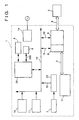
- Fig. 1 is a block diagram common to the respective embodiments of the present invention.
- a printer 4 for obtaining a hard copy and a scanner 7 which reads a desired image and is constituted by a CCD and a read image processing unit 13 are connected to a CPU bus line 12 via direct memory access lines 15.
- a first control circuit unit (not shown) for the printer 4 is constituted by a CPU, a ROM, a RAM, and a gate array, a printer buffer memory 8 connected to the first control circuit unit via an internal Bicentronics cable 3, and an image buffer memory 9 connected to a personal computer 2 via a single external Bicentronics cable 3 are connected to the CPU bus line 12 via the direct memory access lines 15.
- a CPU 20 for controlling the entire apparatus, a ROM 10, and a RAM 11 are connected to the CPU bus line 12. Also, an operation panel 5 and an automatic sheet feed unit 6 are detachably connected to the CPU 20 via connectors 200. Also, a power supply unit 14 is similarly housed.
- a driving control circuit unit for the printer 4 and a driving control circuit unit for the scanner 7 constituted by the CCD of an image reader and the read image processing unit 13 can be mounted on, e.g., a single board.
- a common ground can be assured on a single board, thus greatly improving noise resistance. Since the apparatus can be connected to the personal computer 2 via the single Bicentronics cable, a physical installation can be very simply attained.
- Fig. 2 is a perspective view showing the outer appearance of a housing 100 having a structure for disposing the scanner 7 above the printer 4, and the operation panel 5.
- the Bicentronics-standard interface cable 3 connected to the personal computer 2 serving as a host computer extends from the rear side of the housing 100 to an external portion. Since the scanner 7 is disposed above the printer 4 to realize a two-layered structure, the area of the overall apparatus 1 is almost determined by only that of the printer 4, thus minimizing the area required for the apparatus.
- the width, W, the depth, D, and the height, H, of the apparatus can be respectively set to be about 410 mm, 400 mm, and 230 mm.
- the area required for the apparatus is 1,640 cm 2 at maximum, and the apparatus 1 can be used adjacent to the personal computer 2 on a standard-size desk. It is found as a result of manufacturing the apparatus of this embodiment on a trial basis that the operability can be greatly improved since all the operations can be performed from the front side of the apparatus, as shown in Fig. 2.
- an alignment mark 79 indicated by a broken line is formed on a rear-side portion on the original placing surface of the scanner 7.
- the alignment mark serves as a reference upon setting the original sheet G with its image surface facing down.
- a small-size original sheet having a size other than a standard size e.g., A4 size
- an original sheet which has a size larger than the standard size and cannot be placed on the original placing surface can be aligned.
- the printer 4 since a recording sheet having the same size as that of the original sheet G is set in such a manner that the right side surface of the recording sheet P abuts against the inner side of a sheet guide portion (not shown) using an adjustment plate 21 (to be described later), and the leading end portion of the recording sheet P abuts against the rear-side portion, the recording sheet P is reversed, as indicated by an arrow in Fig. 2, after it is subjected to a recording operation. With this structure, the positional relationship between the original and recording sheet can be easily determined, resulting in a very convenient apparatus.
- Fig. 3 is a partially cutaway plan view showing principal part of the apparatus 1 shown in Fig. 2.
- the printer 4 is constituted by a serial recording type color ink-jet printer proposed by the present applicant.
- the type of the printer 4 is not particularly limited.
- the printer 4 may be constituted by a thermal line head which is fixed in a direction perpendicular to a thermal sheet as the recording sheet P fed in the direction of an arrow P1 in Fig. 3, thus realizing a very low-cost arrangement.
- a color printer may be constituted by fixing three thermal line heads, and looping yellow, magenta, and cyan color ink ribbons on the respective heads.
- a board 18 on which the read image processing unit 13, the CPU bus line 12, the direct memory access lines 15, the first control circuit unit for the printer 4, which unit is constituted by the CPU, ROM, RAM, gate array, and the like, the printer buffer memory 8 connected via the internal Bicentronics cable 3, the image buffer memory 9 connected to the personal computer 2 via the single external Bicentronics cable 3, the CPU 20 for controlling the entire apparatus, and the like, are disposed in an upright state, as shown in Fig. 3.
- a connector portion 3a of the Bicentronics cable 3 is allowed to be housed in the housing 100, thus further reducing the area required for the apparatus.
- the power supply unit 14 is arranged adjacent to the connector portion 3a, and can supply predetermined electric power to the respective constituting portions.
- the printer 4 constitutes a so-called serial printer in which a carriage 45 is reciprocally driven in the direction of an arrow A in Fig. 3 by a motor 50 along guide shafts 43 and 44, two-end portions of which are supported by base portions 41 and 42.
- a black ink cartridge 46, a cyan ink cartridge 47, a magenta ink cartridge 48, and a yellow ink cartridge 49, which are exchangeable, are mounted on the carriage 45 to supply inks of the respective colors to ink-jet heads.
- a capping mechanism portion for attaining preliminary ink ejection of a head 33, and for covering the heads to prevent inks from drying, a cleaning mechanism portion, an ink absorbing member for absorbing an excess ink, and the like are disposed on a portion near the illustrated position of the carriage 45. Since it is easy to access this portion, it is very convenient in terms of use and manufacture.
- the ink cartridges are exchangeable.
- the capacity of the black ink cartridge 46 may be set to be larger than those of other cartridges.
- the capacity of the black ink cartridge 46 may be set to be larger than those of other cartridges.
- the cyan ink cartridge 47, the magenta ink cartridge 48, and the yellow ink cartridge 49 may be mounted, and black may be reproduced by mixing additive primaries.
- a cartridge integrated type head unit which includes the four color ink cartridges and ink-jet heads may be exchanged.
- an ink-jet head unit on which an ink tank obtained by integrating yellow, cyan, and magenta ink cartridges and a black ink tank are detachably mounted may be used.
- the ink cartridges and the heads may be completely separated, as described above.
- a motor 51 for feeding the recording sheet P is disposed on a side opposite to the motor 50 for driving the carriage 45.
- the operation panel 5 arranged at the illustrated position in Fig. 3 has respective operation portions and display portions such as a power-on portion 5f which also serves as a power-on indicator indicating the power-on state, an on-line portion 5h which is used for indicating and setting an exchange state of data with the personal computer 2, a stop portion 5a which is used for indicating and setting a forced stop state, a monochrome copy portion 5c which is used for indicating and setting a monochrome copy mode, a color copy portion 5b which is used for indicating and setting a color copy mode, an in-use display portion 5g for indicating that the apparatus is in operation, and an error display portion 5d which is used for indicating an operation error.
- the operation panel 5 has minimum functions required especially when the apparatus is used as a simple copying machine, i.e., a stand-alone machine.
- Fig. 4 is a perspective view showing the outer appearance of the apparatus 1, and shows a state wherein the respective ink cartridges 46 to 49 are exchanged.
- a lid portion 101 integrated with the operation panel 5 is arranged on the housing 100 to be free to open in the direction of an arrow F in Fig. 5 via a pair of hinge portions 101a, and the respective ink cartridges set on the carriage 45 moved to the standby position can be arbitrarily exchanged.
- a pressing plate 71 with a handle portion 71k is fixed on the scanner 7 to be pivotal about a hinge portion 71a in the direction of an arrow C in Fig. 4. Since this scanner 7 has no support portion on the left front side, a left side plate portion 103 which also serves as a support member is arranged, as shown in Fig. 4.
- the apparatus 1 which requires a small area, and allows an easy access to the ink cartridges 46 to 49 can be constituted.
- members located below the lid portion 101 are not limited to the above-mentioned ink cartridges.
- the respective color ink ribbons may be exchanged at this position.
- An ink cartridge storage portion 101-1 may be arranged inside the lid portion 101 or the housing 100 to store cartridges, so as to always stock auxiliary cartridges.
- auxiliary cartridges in the lid portion or the housing is reasonable since the presence/absence of them can always be confirmed by a quite ordinary operation of opening the lid portion 101 to check the remaining amount of the ink after, e.g., an ink near empty state is informed. Since an ink tank integrated type head is packed in a dry-prevention package and does not require any cap, a simple storage portion need only be arranged.
- Fig. 4 shows a state wherein the lid portion 101 is arranged on the right side of the apparatus. However, if the standby position of the carriage 45 is set on the left side of the apparatus, the lid portion 101 can be arranged on the left side, and such an arrangement is convenient for a left-handed person.
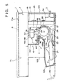
- Fig. 5 is a partially cutaway right sectional view showing principal part of the apparatus 1 of the first embodiment.
- the printer 4 has a recording sheet path, indicated by a broken line, which loads the recording sheet P indicated by a broken line in Fig. 5 from the front side and discharges it to the front side, i.e., has an arrangement for guiding the carriage 45, which is reciprocally driven in a direction perpendicular to the sheet surface with respect to the recording sheet path, along the guide shafts 43 and 44.
- a stopper 52 for holding the black ink cartridge 46, the cyan ink cartridge 47, the magenta ink cartridge 48, and the yellow ink cartridge 49 at predetermined positions is arranged on the carriage 45.
- a sheet supply unit comprises an adjustment plate 21 which is moved stepless in the direction perpendicular to the sheet surface so as to adjust the edge portion of the recording sheet P in the widthwise direction, and an adjustment plate 22 which is moved stepless between a solid line position and a broken line position in Fig. 5 so as to adjust the end portion of the recording sheet.
- the leading end portion of a recording sheet P is inserted between a regulation member 24 and a pressing plate 23 to prevent more than one sheets from being excessively fed, and the pressing plate 23 is pivoted from a broken line position to a solid line position in Fig. 5 by a driving mechanism (not shown), thereby feeding the first sheet to a position between a separation roller 26 and a platen roller 25.
- the recording sheet P is guided to a portion below an ink-jet head 33 on the carriage 45 via a guide roller 27, a guide plate 28, and a guide pressing roller 29, and is subjected to a predetermined color recording operation. Thereafter, the recording sheet P is discharged onto a discharge tray 105 by discharge rollers 30 and spur rollers 31 which do not influence the ink surface.
- the board 18 and the power supply unit 14 can be arranged in the rear portion of the housing 100, as shown in Fig. 5.
- the apparatus can be made compact.
- Fig. 6 is a partially cutaway right sectional view showing principal part of the apparatus 1 as a modification of the first embodiment.
- the same reference numerals in Fig. 6 denote the same parts as in Fig. 5, and only a different arrangement and a non-described portion will be explained to avoid a repetitive description.
- Recording sheets P are stored in a sheet cassette 35 indicated by an alternate long and two short dashed line in Fig. 6, and the sheet cassette 35 is detachable from the front side of the apparatus.
- the scanner 7 is detachably arranged on a top plate 108 via a connector 200.
- the scanner is a flat bed type scanner which comprises, under the pressing plate 71, a light transmission plate 72 for placing a full-color or monochrome original sheet G thereon.
- the scanner also comprises a carriage 75 below the light transmission plate 72.
- the carriage 75 is driven in the longitudinal direction of the original sheet G and serves as an original reading unit for reading the image surface of the original sheet.
- a xenon tube 76 serving as a light source, a mirror 77, and a CCD 78 are mounted on the carriage 75, which reads an image while being moved in the direction of an arrow in Fig. 6.
- Fig. 7 is a sectional view showing principal part of the fixed CCD type scanner 7.
- the scanner 7 is detachably arranged or fixed on the top plate 108 via the connector 200, and comprises, under the pressing plate 71, the light transmission plate 72 for placing a full-color or monochrome original sheet G thereon.
- the CCD 78 is fixed in position, and the xenon tube 76 serving as a light source and a mirror 77-1 are mounted on a carriage 75-1 which serves as an original reading unit for reading the image surface.
- a mirror 77-2 is mounted on a carriage 75-2.
- the carriages 75-1 and 75-2 are synchronously moved by a driving mechanism (not shown) to always maintain a 1 : 2 movement relationship. In this case, when the carriages are moved between a broken line position and a solid line position in Fig. 7, the length of an optical path K is kept constant.
- Fig. 8 is a sectional view showing principal part of the scanner 7 which uses a contact type line sensor.
- Fig. 8 shows the scanner 7 together with the automatic sheet feed unit 6.
- the unit 6 is detachable via the connector 200, and is set at the illustrated position by setting a hook portion 90b after the pressing plate 71 is detached.
- the xenon tube 76 serving as a light source and a contact type line image sensor 86 are mounted on the carriage 75 serving as an original reading unit for reading the image surface, and is fixed at the illustrated position by a driving mechanism (not shown).
- a plurality of original sheets G are placed on a tray 90a, and are conveyed by a pickup roller 92 in the direction of an arrow in Fig. 8. Then, the first original sheet is separated between a friction piece 94 and a separation roller 93, and is fed into a portion between rollers 95 and 96. Then, the original sheet is guided by a guide (not shown), as shown in Fig. 8, and is fed onto the contact type line image sensor 86. At this position, the original sheet is subjected to an original reading operation, and is then fed onto a discharge tray 90d by discharge rollers 99.
- Fig. 9 is a sectional view of an apparatus according to the second embodiment.
- the same reference numerals in Fig. 9 denote the same parts as in the first embodiment, and only a different arrangement and a non-described portion will be explained to avoid a repetitive description.
- the scanner 7 comprises an original sheet path which loads a full-color or monochrome original sheet G from the front side and discharges it onto a discharge tray 89 on the rear side, and an original reading unit which is fixed so that its longitudinal direction extends in a direction perpendicular to the original sheet path. For this reason, original sheets G are placed on a tray 81 with their image surfaces facing down.
- the first original sheet is separated by a separation roller 83 and a pressing plate 82, and is fed into a portion between rollers 84 and 85. Thereafter, the original sheet is fed into a portion between a platen roller 85 and a proximity line image sensor 86, and is subjected to an original reading operation. Then, the original sheet is fed onto the discharge tray 89 by discharge rollers 87.
- an image processing apparatus which can minimize the area required for the scanner 7 and the printer 4, and can take effective countermeasure against noise, can be provided.
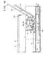
- Fig. 10 is a sectional view of an apparatus according to the third embodiment.
- the same reference numerals in Fig. 10 denote the same parts as in the first embodiment, and only a different arrangement and a non-described portion will be explained to avoid a repetitive description.
- the printer 4 is a serial printer comprising a recording sheet path which loads a recording sheet P from a tray 111 on the front side, and discharges it onto a discharge tray 112 on the rear side, and an ink-jet head 33 which is reciprocally driven in a direction substantially perpendicular to the recording sheet path. For this reason, a separation roller 26 and a separation plate 23 are located at the entrance portion of the tray 112.
- the first recording sheet is separated by the separation roller 26 and the separation plate 23, and is fed into a portion between rollers 29. Thereafter, the recording sheet is subjected to a predetermined color recording operation by the ink-jet head 33, and is then discharged onto the discharge tray 111 by discharge rollers 30 and spur rollers 31 which do not influence the ink surface.
- the apparatus can be made compact.
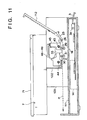
- Fig. 11 is a sectional view of an apparatus according to the fourth embodiment.
- the same reference numerals in Fig. 11 denote the same parts as in the first embodiment, and only a different arrangement and a non-described portion will be explained to avoid a repetitive description.
- the printer 4 is a serial printer comprising a recording sheet path which loads a recording sheet P from the tray 112 on the rear side, and discharges it onto the discharge tray 111 on the front side, and the ink-jet head 33 which is reciprocally driven in a direction substantially perpendicular to the recording sheet path.
- the separation roller 26 and the separation plate 23 are located at the entrance portion of the tray 112.
- the first recording sheet is separated by the separation roller 26 and the separation plate 23, and is fed into a portion between the rollers 29. Thereafter, the recording sheet is subjected to a predetermined color recording operation by the ink-jet head 33, and is then discharged onto the discharge tray 111 by the discharge rollers 30 and the spur rollers 31 which do not influence the ink surface. Since the board 18 and the power supply unit 14 can be disposed on the bottom surface portion of the housing 100, as shown in Fig. 11, the apparatus can be made compact.
- an image processing apparatus which can minimize the area required for the scanner 7 and the printer 4, and can take effective countermeasure against noise can be provided.
- the present invention may be appropriately applied to a single system or a plurality of systems.
- an image processing apparatus which uses a Bicentronics-standard interface cable to prevent cables from being complicated, can minimize the area required for the scanner and printer, can take effective countermeasure against noise, and can obtain a desired hard copy by setting original and recording sheets to have an accurate relative positional relationship therebetween, can be provided.
- an image processing apparatus which uses a Bicentronics-standard interface cable to prevent cables from being complicated, can minimize the area required for the scanner and printer, can take effective countermeasure against noise, allows a user to handle original and recording sheets from the front side with good operability, and can obtain a desired hard copy by setting original and recording sheets to have an accurate relative positional relationship therebetween, can be provided.
- an image processing apparatus which can constitute a simple copying machine that can minimize the area required for the scanner and printer, has good operability, and can obtain a desired hard copy by setting original and recording sheets to have an accurate relative positional relationship therebetween, can be provided.
- an image processing apparatus which uses a Bicentronics-standard interface cable to prevent cables from being complicated, can minimize the area required for the scanner and printer, can take effective countermeasure against noise, and can obtain a desired hard copy by setting original and recording sheets to have an accurate relative positional relationship therebetween, can be provided.
- an image processing apparatus which can constitute a simple copying machine that can minimize the area required for the scanner and printer, has good operability, and can obtain a desired hard copy by setting original and recording sheets to have an accurate relative positional relationship therebetween, can be provided.
- an image processing apparatus which uses a Bicentronics-standard interface cable to prevent cables from being complicated, can minimize the area required for the scanner and printer, can take effective countermeasure against noise, can restart a recording operation any time by storing auxiliary recording media in the apparatus, and can obtain a desired hard copy, can be provided.
- the image reading device in order to integrate a recording device for obtaining a hard copy and an image reading device for reading a desired image, the image reading device is disposed above the recording device, and the apparatus has a housing for housing a first control circuit unit for the recording unit and a second control circuit unit for the image reading device, a storage unit for temporarily storing an image processed between the apparatus and the host computer side and an image to be output to the recording device, and a power supply unit, so as to minimize the area required for the apparatus.
- the apparatus takes a countermeasure against noise.
- the apparatus can be connected to the host computer via only one Bicentronics-standard interface cable, and can obtain hard copies of different sizes.
Claims (21)
- Bildverarbeitungsgerät, das eine Aufzeichnungseinrichtung (4), welche auf einem Aufzeichnungsblatt (P) mittels Aufzeichnungsmittel (45) aufzeichnet, und eine Bildleseeinrichtung (7) integriert, welche ein Originalblatt (G) mittels Lesemittel (75) liest,
wobei
die Aufzeichnungseinrichtung (4) innerhalb eines Gehäuses (100) vorgesehen ist und die Bildleseeinrichtung (7) über der Aufzeichnungseinrichtung (4) in dem Gehäuse (100) vorgesehen ist, so daß die Bildleseeinrichtung (7) und die Aufzeichnungseinrichtung (4) auf integrale Weise darauf angeordnet sind, das Gehäuse (100) ferner eine Steuerschaltkreisplatine (18) umfaßt, auf welcher eine erste Steuerschaltkreiseinheit (8, 9) für die Aufzeichnungseinrichtung (4) und eine zweite Steuerschaltkreiseinheit (13) für die Bildleseeinrichtung (7) angeordnet sind, wobei die Steuerschaltkreisplatine (18) mit einem Host-Rechner (2) verbunden ist, welcher über ein Bicentronics-Standardschnittstellenkabel (3) separat vorgesehen ist, wobei die Aufzeichnungseinrichtung (4) Aufzeichnungsblatt-Handhabungsmittel aufweist, welche den Einzug des Aufzeichnungsblattes (P) von der Stirnseite des Bildverarbeitungsgerätes (1) realisieren, von welcher Stirnseite ein Anwender eine in dem Gerät (1) aufgenommene Bedienungskonsole (15) bedient, und die Leseeinrichtung (7) Originalblatt-Handhabungsmittel aufweist, welche den Einzug des Originalblattes (G) von der Stirnseite realisieren, und wobei beide Handhabungsmittel angeordnet sind, um jeweils das Aufzeichnungsblatt (G) und das Originalblatt (G) in der richtigen Lage zum Lesen und Aufzeichnen vorzusehen, wenn beide Blätter (P, G) in die Handhabungsmittel mit derselben Orientierung von der Stirnseite des Gerätes eingezogen sind. - Gerät nach Anspruch 1,
wobei die Aufzeichnungseinrichtung (4) eine Aufzeichnungsblattzufuhreinheit (21, 22) mit einer Blattgrößenjustierfunktion hat, welche das Plazieren von Aufzeichnungsblättern (P) unterschiedlicher Größen erlaubt, um eine Hardcopy zu erstellen. - Gerät nach Anspruch 1,
wobei die Leseeinrichtung (7) einen Original-Ablagetisch (72) zum Plazieren des Originalblattes nach Ausrichten eines führenden Endabschnittes des Originalblattes (G) aufweist, um Originalblätter verschiedener Größen zu lesen. - Gerät nach einem der Ansprüche 1 bis 3,
wobei die Aufzeichnungseinrichtung (4) als ein serieller Drucker ausgebildet ist, welcher einen Aufzeichnungsblatt-Weg (28), welcher das Aufzeichnungsblatt (P) von der Stirnseite lädt und das Aufzeichnungsblatt (P) an die Stirnseite ausgibt, und eine Aufzeichnungseinheit (46 - 49) aufweist, welche wechselweise in einer im wesentlichen senkrecht zu dem Aufzeichnungsblatt-Weg (28) verlaufenden Richtung angetrieben wird. - Gerät nach einem der Ansprüche 1 bis 3,
wobei die Aufzeichnungseinrichtung (4) als ein serieller Drucker ausgebildet ist, welcher einen Aufzeichnungsblatt-Weg (28), welcher das Aufzeichnungsblatt (P) von der Stirnseite lädt und das Aufzeichnungsblatt (P) an eine Rückseite ausgibt, und eine Aufzeichnungseinheit aufweist, welche wechselweise in einer im wesentlichen senkrecht zu dem Aufzeichnungsblatt-Weg (28) verlaufenden Richtung angetrieben wird. - Gerät nach einem der Ansprüche 1 bis 3,
wobei die Aufzeichnungseinrichtung (4) als ein serieller Drucker ausgebildet ist, welcher einen Aufzeichnungsblatt-Weg (28), welcher das Aufzeichnungsblatt (P) von einer Rückseite lädt und das Aufzeichnungsblatt an die Stirnseite ausgibt, und eine Aufzeichnungseinheit (4) aufweist, welche wechselweise in einer im wesentlichen senkrecht zu dem Aufzeichnungsblatt-Weg (28) verlaufenden Richtung angetrieben wird. - Gerät nach einem der Ansprüche 1 bis 3,
wobei die Aufzeichnungseinrichtung (4) einen Tintenstrahlkopf zum Ausstoß von Farbtinten von zumindest drei Primärfarben auf das Aufzeichnungsblatt (P) aufweist, wobei die Aufzeichnungseinrichtung als Vollfarbdrucker ausgebildet ist. - Gerät nach einem der Ansprüche 1 bis 3,
wobei die Aufzeichnungseinrichtung (4) einen Tintenstrahlkopf zum Ausstoß schwarzer Tinte auf das Aufzeichnungsblatt aufweist, wobei die Aufzeichnungseinrichtung als Monochrom-Drucker ausgebildet ist. - Gerät nach einem der Ansprüche 1 bis 3,
wobei die Aufzeichnungseinrichtung (4) einen Tintenstrahlkopf zum Ausstoß schwarzer Tinte und dreier Primärfarben-Tinten auf das Aufzeichnungsblatt aufweist, wobei die Aufzeichnungseinrichtung auf willkürliche Weise als eine eines Vollfarbdruckers und eines Monochromdruckers einsetzbar ist. - Gerät nach einem der Ansprüche 1 bis 3,
wobei die Aufzeichnungseinrichtung einen thermischen Zeilenkopf aufweist, welcher so angeordnet ist, daß eine Längsrichtung davon sich in einer im wesentlichen senkrecht zu dem Aufzeichnungsblatt-Weg (28) verlaufenden Richtung erstreckt und die Aufzeichnungseinrichtung als ein monochromer thermischer Drucker ausgebildet ist. - Gerät nach Anspruch 2 oder 3,
wobei die Aufzeichnungseinrichtung (4) eine automatische Blattfördereinheit zum Zuführen von jedem Aufzeichnungsblatt einer Vielzahl von Aufzeichnungsblättern aufweist, welche auf der Aufzeichnungsblattzufuhreinheit (21, 22) in Richtung der Aufzeichnungseinrichtung plaziert sind. - Gerät nach Anspruch 11,
wobei die automatische Blattfördereinheit eine Aufzeichnungsblattkassette aufweist, welche eine Vielzahl von Aufzeichnungsblättern (P) lädt und von der Stirnseite an/von das bzw. dem Gerät angebracht/lösbar ist. - Gerät nach einem der Ansprüche 1 bis 3,
wobei die Bildleseeinrichtung eine Original-Ablageeinheit (7) mit einer Lichttransmissionsplatte (72) zum Auflegen eines Vollfarb- oder Monochrom- Originalblattes (G) und eine Original-Leseeinheit aufweist, welche in einer Längsrichtung des Originalblattes in einem Abschnitt unter der Original-Ablageeinheit angetrieben wird und eine Bildoberfläche des Originalblattes liest. - Gerät nach Anspruch 13,
wobei die Bildleseeinrichtung (7) eine Druckplatte (71), welche auf einem rückseitigen Abschnitt der Original-Ablageeinheit so gehalten ist, daß ein Stirnabschnitt davon öffenbar ist, und eine Ausrichtungsmarkierung (79) aufweist, welche auf einem von der Stirnseite gesehenen rechten rückseitigen Abschnitt angeordnet ist und dazu dient, das Originalblatt (G) auszurichten, wobei der führende Endabschnitt des Originalblattes an die Ausrichtungsmarkierung (79) angepaßt ist. - Gerät nach einem der Ansprüche 1 bis 3,
wobei die Bildleseeinrichtung (7) einen Originalblatt-Weg, welcher ein Vollfarb- oder Monochrom- Originalblatt von der Stirnseite lädt und das Originalblatt von der Stirnseite ausgibt und das Originalblatt an eine Rückseite ausgibt, und eine Original-Leseeinheit aufweist, welche so befestigt ist, daß eine Längsrichtung davon sich in einer im wesentlichen senkrecht zu dem Originalblatt-Weg verlaufenden Richtung erstreckt. - Gerät nach einem der Ansprüche 1 bis 3,
wobei die Bildleseeinrichtung (7) einen Originalblatt-Weg, welcher ein Vollfarb- oder Monochrom- Originalblatt von einer Rückseite lädt und das Originalblatt an die Stirnseite ausgibt, und eine Original-Leseeinheit aufweist, welche so befestigt ist, daß eine Längsrichtung davon sich in einer im wesentlichen senkrecht zu dem Originalblatt-Weg verlaufenden Richtung erstreckt. - Gerät nach Anspruch 15,
wobei die Original-Leseeinrichtung (7) eine Zeilenbildsensoreinheit (77) aufweist, welche ein Gleichvergrößerungs-Optiksystem vom Kontakt-Typ oder ein Verkleinerungs-Optiksystem aufweist, wobei eine Lesebreite mindestens mit der Bildoberfläche des Originalblattes korrespondiert. - Gerät nach Anspruch 18,
wobei der Zeilenbildsensor der Original-Leseeinheit wie ein CCD-Element (86) befestigt ist und ein Verkleinerungs-Optiksystem aufweist, in welchem eine Lichtquelle und ein optisches Linsensystem auf integrale Weise gebildet sind. - Gerät nach einem der Ansprüche 1 bis 3,
wobei die Bildleseeinrichtung eine Originalblattzufuhreinheit mit einer Originalblattgrößenjustierfunktion, welche das Plazieren von Originalblättern unterschiedlicher Größen erlaubt, und eine automatische Originalblattfördereinheit zum Zuführen von jedem Originalblatt einer Vielzahl von Originalblättern aufweist, welche auf der Originalblattzufuhreinheit in Richtung der Leseeinheit plaziert sind. - Gerät nach Anspruch 19,
wobei die automatische Originalblattzufuhreinheit auf einer Original-Ablageeinheit lösbar angeordnet ist. - Bildverarbeitungsgerät nach Anspruch 1,
wobei das Gehäuse (1) einen auf seiner Seite befestigten Bedienungsabschnitt (5) aufweist und der Bedienungsabschnitt (5) die Leseeinrichtung (7) und die Aufzeichnungseinrichtung (4) verbindet.
Applications Claiming Priority (12)
| Application Number | Priority Date | Filing Date | Title |
|---|---|---|---|
| JP32910694 | 1994-12-28 | ||
| JP32832494 | 1994-12-28 | ||
| JP329107/94 | 1994-12-28 | ||
| JP32832594 | 1994-12-28 | ||
| JP6328325A JPH08186678A (ja) | 1994-12-28 | 1994-12-28 | 画像処理装置 |
| JP329106/94 | 1994-12-28 | ||
| JP328324/94 | 1994-12-28 | ||
| JP32910794A JPH08183224A (ja) | 1994-12-28 | 1994-12-28 | 画像処理装置 |
| JP32832494A JPH08183223A (ja) | 1994-12-28 | 1994-12-28 | 画像処理装置 |
| JP328325/94 | 1994-12-28 | ||
| JP6329106A JPH08186680A (ja) | 1994-12-28 | 1994-12-28 | 画像処理装置 |
| JP32910794 | 1994-12-28 |
Publications (3)
| Publication Number | Publication Date |
|---|---|
| EP0720343A2 EP0720343A2 (de) | 1996-07-03 |
| EP0720343A3 EP0720343A3 (de) | 1996-12-11 |
| EP0720343B1 true EP0720343B1 (de) | 2002-03-20 |
Family
ID=27480409
Family Applications (1)
| Application Number | Title | Priority Date | Filing Date |
|---|---|---|---|
| EP95120587A Expired - Lifetime EP0720343B1 (de) | 1994-12-28 | 1995-12-27 | Bildverarbeitungsgerät |
Country Status (3)
| Country | Link |
|---|---|
| US (1) | US5844687A (de) |
| EP (1) | EP0720343B1 (de) |
| DE (1) | DE69525918T2 (de) |
Families Citing this family (21)
| Publication number | Priority date | Publication date | Assignee | Title |
|---|---|---|---|---|
| KR100297977B1 (ko) | 1996-04-23 | 2001-10-26 | 모리시타 요이찌 | 칼라전자사진장치 |
| JP3418308B2 (ja) * | 1997-05-01 | 2003-06-23 | 株式会社リコー | 画像形成装置 |
| JP3584159B2 (ja) * | 1997-05-23 | 2004-11-04 | キヤノン株式会社 | 記録装置 |
| JP3912568B2 (ja) * | 1997-11-07 | 2007-05-09 | ブラザー工業株式会社 | 印字装置 |
| US6128455A (en) * | 1998-04-13 | 2000-10-03 | Ricoh Company, Ltd. | Automatic document feeder having an open-and-close cover |
| US6671060B1 (en) * | 1998-10-26 | 2003-12-30 | Hewlett-Packard Development Company, L.P. | Image forming system and method of operating an image forming system |
| JP2001097611A (ja) * | 1999-07-26 | 2001-04-10 | Canon Inc | 画像形成装置 |
| US6647243B2 (en) * | 2000-10-16 | 2003-11-11 | Canon Kabushiki Kaisha | Sheet treating apparatus, method of mounting sheet treating apparatus, and image forming apparatus |
| AUPS048102A0 (en) * | 2002-02-13 | 2002-03-07 | Silverbrook Research Pty. Ltd. | Methods and systems (ap77) |
| JP2004347720A (ja) * | 2003-05-20 | 2004-12-09 | Brother Ind Ltd | 画像形成装置 |
| JP2005252892A (ja) * | 2004-03-05 | 2005-09-15 | Brother Ind Ltd | 画像形成装置 |
| JP4419614B2 (ja) | 2004-03-05 | 2010-02-24 | ブラザー工業株式会社 | 画像形成装置 |
| JP2005266522A (ja) * | 2004-03-19 | 2005-09-29 | Brother Ind Ltd | 画像形成装置 |
| JP4491301B2 (ja) * | 2004-08-25 | 2010-06-30 | 株式会社リコー | インクジェット記録装置及びその制御方法 |
| JP2006119236A (ja) * | 2004-10-20 | 2006-05-11 | Brother Ind Ltd | 画像形成装置 |
| JP4765428B2 (ja) * | 2005-06-20 | 2011-09-07 | 富士ゼロックス株式会社 | 画像形成装置 |
| US20120102705A1 (en) * | 2010-10-27 | 2012-05-03 | Murray Richard A | Method of assembling a multifunction printer |
| CN102984426B (zh) * | 2011-09-05 | 2015-06-03 | 珠海赛纳打印科技股份有限公司 | 图像读取设备以及成像装置 |
| JP6016538B2 (ja) * | 2012-09-07 | 2016-10-26 | キヤノン株式会社 | プリント装置 |
| JP6142626B2 (ja) | 2013-03-29 | 2017-06-07 | ブラザー工業株式会社 | 画像読取装置 |
| US10498913B2 (en) * | 2016-07-29 | 2019-12-03 | Canon Kabushiki Kaisha | Image forming apparatus |
Citations (5)
| Publication number | Priority date | Publication date | Assignee | Title |
|---|---|---|---|---|
| EP0506469A2 (de) * | 1991-03-29 | 1992-09-30 | Canon Kabushiki Kaisha | Bildverarbeitungsgerät und Kopiergerät |
| EP0552746A1 (de) * | 1992-01-21 | 1993-07-28 | Sharp Kabushiki Kaisha | Faksimilegerät |
| EP0554115A1 (de) * | 1992-01-31 | 1993-08-04 | Canon Kabushiki Kaisha | Bildverarbeitungsverfahren und -gerät |
| EP0570892A1 (de) * | 1992-05-18 | 1993-11-24 | Canon Kabushiki Kaisha | Verbindung zwischen Rechnerperipheriegeräten |
| US5283662A (en) * | 1991-04-10 | 1994-02-01 | Minolta Camera Kabushiki Kaisha | Image reading apparatus controllable by external apparatus |
Family Cites Families (15)
| Publication number | Priority date | Publication date | Assignee | Title |
|---|---|---|---|---|
| JPS6249344A (ja) * | 1985-08-28 | 1987-03-04 | Sharp Corp | 自動原稿送り機能を有する複写機 |
| US5216158A (en) * | 1988-03-07 | 1993-06-01 | Hoechst Aktiengesellschaft | Oxadiazole compounds containing 4,6-bis-trichloromethyl-S-triazin-2-yl groups, process for their preparation |
| US5208612A (en) * | 1989-12-06 | 1993-05-04 | Ricoh Company, Ltd. | Image recording apparatus constituting of selectable units |
| EP0495433A3 (en) * | 1991-01-15 | 1993-04-14 | Hewlett-Packard Company | Combined printer, copier, scanner, and facsimile apparatus and method of operation |
| JP3101343B2 (ja) * | 1991-06-03 | 2000-10-23 | キヤノン株式会社 | カラー画像形成装置及びカラー画像処理装置 |
| US5188351A (en) * | 1991-10-04 | 1993-02-23 | Hewlett-Packard Company | Multi-size paper cassette having a sheet size indicator |
| US5581669A (en) * | 1992-12-18 | 1996-12-03 | Microsoft Corporation | System and method for peripheral data transfer |
| JPH06276334A (ja) * | 1993-03-23 | 1994-09-30 | Ricoh Co Ltd | 複写システム |
| US5354044A (en) * | 1993-04-30 | 1994-10-11 | Hewlett-Packard Company | Paper trays for computer driven printer |
| JPH06326841A (ja) * | 1993-05-11 | 1994-11-25 | Ricoh Co Ltd | 複合機 |
| JP3547153B2 (ja) * | 1993-06-14 | 2004-07-28 | 株式会社リコー | ディジタル複写機システム |
| US5510896A (en) * | 1993-06-18 | 1996-04-23 | Xerox Corporation | Automatic copy quality correction and calibration |
| US5532825A (en) * | 1993-08-30 | 1996-07-02 | Hewlett-Packard Company | Add-on scanner for existing ink jet printer |
| JPH07306730A (ja) * | 1994-05-10 | 1995-11-21 | Ricoh Co Ltd | 複合複写機 |
| US5573236A (en) * | 1994-08-05 | 1996-11-12 | Xerox Corporation | Variable sheet guide position sensor |
-
1995
- 1995-12-27 EP EP95120587A patent/EP0720343B1/de not_active Expired - Lifetime
- 1995-12-27 DE DE69525918T patent/DE69525918T2/de not_active Expired - Lifetime
- 1995-12-28 US US08/579,732 patent/US5844687A/en not_active Expired - Lifetime
Patent Citations (5)
| Publication number | Priority date | Publication date | Assignee | Title |
|---|---|---|---|---|
| EP0506469A2 (de) * | 1991-03-29 | 1992-09-30 | Canon Kabushiki Kaisha | Bildverarbeitungsgerät und Kopiergerät |
| US5283662A (en) * | 1991-04-10 | 1994-02-01 | Minolta Camera Kabushiki Kaisha | Image reading apparatus controllable by external apparatus |
| EP0552746A1 (de) * | 1992-01-21 | 1993-07-28 | Sharp Kabushiki Kaisha | Faksimilegerät |
| EP0554115A1 (de) * | 1992-01-31 | 1993-08-04 | Canon Kabushiki Kaisha | Bildverarbeitungsverfahren und -gerät |
| EP0570892A1 (de) * | 1992-05-18 | 1993-11-24 | Canon Kabushiki Kaisha | Verbindung zwischen Rechnerperipheriegeräten |
Also Published As
| Publication number | Publication date |
|---|---|
| DE69525918T2 (de) | 2002-08-01 |
| DE69525918D1 (de) | 2002-04-25 |
| EP0720343A3 (de) | 1996-12-11 |
| US5844687A (en) | 1998-12-01 |
| EP0720343A2 (de) | 1996-07-03 |
Similar Documents
| Publication | Publication Date | Title |
|---|---|---|
| EP0720343B1 (de) | Bildverarbeitungsgerät | |
| EP2163391B1 (de) | Drucker | |
| US7270492B2 (en) | Computer system having integrated printer and keyboard | |
| US8599396B2 (en) | Image forming apparatus | |
| US7426113B2 (en) | Electronic device | |
| US7808683B2 (en) | Electrical appliance equipped with liquid crystal display | |
| US20070201100A1 (en) | Multifunction device | |
| EP0529614B1 (de) | Faksimilegerät | |
| US20070002116A1 (en) | Media support for an imaging apparatus | |
| EP0529615B1 (de) | Faksimilegerät | |
| JP2006205655A (ja) | インクジェット記録装置 | |
| US6264384B1 (en) | Multi-functional apparatus having a small size and method for same | |
| US7525683B2 (en) | Image forming apparatus | |
| JPH08186680A (ja) | 画像処理装置 | |
| US6965392B2 (en) | Image reading and recording apparatus | |
| US20060158468A1 (en) | Image input/output module and image input/output apparatus and method | |
| US7652777B2 (en) | Method in a copying apparatus for controlling image orientation of a document | |
| US20070097457A1 (en) | Image reader and image forming device | |
| JPH08183223A (ja) | 画像処理装置 | |
| JPH08183224A (ja) | 画像処理装置 | |
| JPH08186678A (ja) | 画像処理装置 | |
| JP2004082478A (ja) | 画像処理装置 | |
| US20220329708A1 (en) | Reading apparatus | |
| JP3397714B2 (ja) | 記録装置及び画像処理装置 | |
| JP2004088350A (ja) | 画像読取記録装置 |
Legal Events
| Date | Code | Title | Description |
|---|---|---|---|
| PUAI | Public reference made under article 153(3) epc to a published international application that has entered the european phase |
Free format text: ORIGINAL CODE: 0009012 |
|
| AK | Designated contracting states |
Kind code of ref document: A2 Designated state(s): DE ES FR GB IT |
|
| PUAL | Search report despatched |
Free format text: ORIGINAL CODE: 0009013 |
|
| AK | Designated contracting states |
Kind code of ref document: A3 Designated state(s): DE ES FR GB IT |
|
| 17P | Request for examination filed |
Effective date: 19970428 |
|
| 17Q | First examination report despatched |
Effective date: 19981124 |
|
| GRAG | Despatch of communication of intention to grant |
Free format text: ORIGINAL CODE: EPIDOS AGRA |
|
| GRAG | Despatch of communication of intention to grant |
Free format text: ORIGINAL CODE: EPIDOS AGRA |
|
| GRAH | Despatch of communication of intention to grant a patent |
Free format text: ORIGINAL CODE: EPIDOS IGRA |
|
| REG | Reference to a national code |
Ref country code: GB Ref legal event code: IF02 |
|
| GRAH | Despatch of communication of intention to grant a patent |
Free format text: ORIGINAL CODE: EPIDOS IGRA |
|
| GRAA | (expected) grant |
Free format text: ORIGINAL CODE: 0009210 |
|
| AK | Designated contracting states |
Kind code of ref document: B1 Designated state(s): DE ES FR GB IT |
|
| PG25 | Lapsed in a contracting state [announced via postgrant information from national office to epo] |
Ref country code: IT Free format text: LAPSE BECAUSE OF FAILURE TO SUBMIT A TRANSLATION OF THE DESCRIPTION OR TO PAY THE FEE WITHIN THE PRE;WARNING: LAPSES OF ITALIAN PATENTS WITH EFFECTIVE DATE BEFORE 2007 MAY HAVE OCCURRED AT ANY TIME BEFORE 2007. THE CORRECT EFFECTIVE DATE MAY BE DIFFERENT FROM THE ONE RECORDED.SCRIBED TIME-LIMIT Effective date: 20020320 Ref country code: FR Free format text: LAPSE BECAUSE OF FAILURE TO SUBMIT A TRANSLATION OF THE DESCRIPTION OR TO PAY THE FEE WITHIN THE PRESCRIBED TIME-LIMIT Effective date: 20020320 |
|
| REF | Corresponds to: |
Ref document number: 69525918 Country of ref document: DE Date of ref document: 20020425 |
|
| PG25 | Lapsed in a contracting state [announced via postgrant information from national office to epo] |
Ref country code: ES Free format text: LAPSE BECAUSE OF FAILURE TO SUBMIT A TRANSLATION OF THE DESCRIPTION OR TO PAY THE FEE WITHIN THE PRESCRIBED TIME-LIMIT Effective date: 20020925 |
|
| EN | Fr: translation not filed | ||
| PLBE | No opposition filed within time limit |
Free format text: ORIGINAL CODE: 0009261 |
|
| STAA | Information on the status of an ep patent application or granted ep patent |
Free format text: STATUS: NO OPPOSITION FILED WITHIN TIME LIMIT |
|
| 26N | No opposition filed |
Effective date: 20021223 |
|
| PGFP | Annual fee paid to national office [announced via postgrant information from national office to epo] |
Ref country code: DE Payment date: 20131231 Year of fee payment: 19 Ref country code: GB Payment date: 20131217 Year of fee payment: 19 |
|
| REG | Reference to a national code |
Ref country code: DE Ref legal event code: R119 Ref document number: 69525918 Country of ref document: DE |
|
| GBPC | Gb: european patent ceased through non-payment of renewal fee |
Effective date: 20141227 |
|
| PG25 | Lapsed in a contracting state [announced via postgrant information from national office to epo] |
Ref country code: DE Free format text: LAPSE BECAUSE OF NON-PAYMENT OF DUE FEES Effective date: 20150701 Ref country code: GB Free format text: LAPSE BECAUSE OF NON-PAYMENT OF DUE FEES Effective date: 20141227 |