EP0720163B1 - Appareil d'enregistrement et de reproduction magnétique et cassette de nettoyage pour cet appareil - Google Patents
Appareil d'enregistrement et de reproduction magnétique et cassette de nettoyage pour cet appareil Download PDFInfo
- Publication number
- EP0720163B1 EP0720163B1 EP95309475A EP95309475A EP0720163B1 EP 0720163 B1 EP0720163 B1 EP 0720163B1 EP 95309475 A EP95309475 A EP 95309475A EP 95309475 A EP95309475 A EP 95309475A EP 0720163 B1 EP0720163 B1 EP 0720163B1
- Authority
- EP
- European Patent Office
- Prior art keywords
- cleaning
- cassette
- tape
- cleaning cassette
- mic
- Prior art date
- Legal status (The legal status is an assumption and is not a legal conclusion. Google has not performed a legal analysis and makes no representation as to the accuracy of the status listed.)
- Expired - Lifetime
Links
- 238000004140 cleaning Methods 0.000 title claims description 365
- 239000004065 semiconductor Substances 0.000 claims description 7
- 239000000463 material Substances 0.000 description 9
- 238000010586 diagram Methods 0.000 description 8
- 239000002923 metal particle Substances 0.000 description 5
- 238000012545 processing Methods 0.000 description 5
- 238000012937 correction Methods 0.000 description 4
- 230000004044 response Effects 0.000 description 4
- 230000000007 visual effect Effects 0.000 description 4
- 238000007906 compression Methods 0.000 description 3
- 230000006835 compression Effects 0.000 description 3
- 238000001514 detection method Methods 0.000 description 3
- 239000000428 dust Substances 0.000 description 3
- 229910001651 emery Inorganic materials 0.000 description 2
- 239000004744 fabric Substances 0.000 description 2
- 239000007788 liquid Substances 0.000 description 2
- 230000007246 mechanism Effects 0.000 description 2
- 238000000034 method Methods 0.000 description 2
- SNICXCGAKADSCV-JTQLQIEISA-N (-)-Nicotine Chemical compound CN1CCC[C@H]1C1=CC=CN=C1 SNICXCGAKADSCV-JTQLQIEISA-N 0.000 description 1
- PRWJPWSKLXYEPD-UHFFFAOYSA-N 4-[4,4-bis(5-tert-butyl-4-hydroxy-2-methylphenyl)butan-2-yl]-2-tert-butyl-5-methylphenol Chemical compound C=1C(C(C)(C)C)=C(O)C=C(C)C=1C(C)CC(C=1C(=CC(O)=C(C=1)C(C)(C)C)C)C1=CC(C(C)(C)C)=C(O)C=C1C PRWJPWSKLXYEPD-UHFFFAOYSA-N 0.000 description 1
- 101001121074 Homo sapiens MICOS complex subunit MIC13 Proteins 0.000 description 1
- 102100026627 MICOS complex subunit MIC13 Human genes 0.000 description 1
- 230000015556 catabolic process Effects 0.000 description 1
- 235000019504 cigarettes Nutrition 0.000 description 1
- 238000013144 data compression Methods 0.000 description 1
- 230000007547 defect Effects 0.000 description 1
- 238000000151 deposition Methods 0.000 description 1
- 230000003292 diminished effect Effects 0.000 description 1
- 230000000694 effects Effects 0.000 description 1
- 230000014509 gene expression Effects 0.000 description 1
- 230000006872 improvement Effects 0.000 description 1
- 230000000977 initiatory effect Effects 0.000 description 1
- 238000003780 insertion Methods 0.000 description 1
- 230000037431 insertion Effects 0.000 description 1
- 239000000696 magnetic material Substances 0.000 description 1
- 239000006249 magnetic particle Substances 0.000 description 1
- 239000006247 magnetic powder Substances 0.000 description 1
- 239000002184 metal Substances 0.000 description 1
- 238000012986 modification Methods 0.000 description 1
- 230000004048 modification Effects 0.000 description 1
- 238000012544 monitoring process Methods 0.000 description 1
- 229960002715 nicotine Drugs 0.000 description 1
- SNICXCGAKADSCV-UHFFFAOYSA-N nicotine Natural products CN1CCCC1C1=CC=CN=C1 SNICXCGAKADSCV-UHFFFAOYSA-N 0.000 description 1
- 239000002245 particle Substances 0.000 description 1
- 230000008569 process Effects 0.000 description 1
- 235000019505 tobacco product Nutrition 0.000 description 1
Images


Classifications
-
- G—PHYSICS
- G11—INFORMATION STORAGE
- G11B—INFORMATION STORAGE BASED ON RELATIVE MOVEMENT BETWEEN RECORD CARRIER AND TRANSDUCER
- G11B15/00—Driving, starting or stopping record carriers of filamentary or web form; Driving both such record carriers and heads; Guiding such record carriers or containers therefor; Control thereof; Control of operating function
- G11B15/02—Control of operating function, e.g. switching from recording to reproducing
- G11B15/05—Control of operating function, e.g. switching from recording to reproducing by sensing features present on or derived from record carrier or container
- G11B15/06—Control of operating function, e.g. switching from recording to reproducing by sensing features present on or derived from record carrier or container by sensing auxiliary features on record carriers or containers, e.g. to stop machine near the end of a tape
- G11B15/07—Control of operating function, e.g. switching from recording to reproducing by sensing features present on or derived from record carrier or container by sensing auxiliary features on record carriers or containers, e.g. to stop machine near the end of a tape on containers
-
- G—PHYSICS
- G11—INFORMATION STORAGE
- G11B—INFORMATION STORAGE BASED ON RELATIVE MOVEMENT BETWEEN RECORD CARRIER AND TRANSDUCER
- G11B23/00—Record carriers not specific to the method of recording or reproducing; Accessories, e.g. containers, specially adapted for co-operation with the recording or reproducing apparatus ; Intermediate mediums; Apparatus or processes specially adapted for their manufacture
- G11B23/02—Containers; Storing means both adapted to cooperate with the recording or reproducing means
- G11B23/04—Magazines; Cassettes for webs or filaments
- G11B23/049—Cassettes for special applications not otherwise provided for
-
- G—PHYSICS
- G11—INFORMATION STORAGE
- G11B—INFORMATION STORAGE BASED ON RELATIVE MOVEMENT BETWEEN RECORD CARRIER AND TRANSDUCER
- G11B23/00—Record carriers not specific to the method of recording or reproducing; Accessories, e.g. containers, specially adapted for co-operation with the recording or reproducing apparatus ; Intermediate mediums; Apparatus or processes specially adapted for their manufacture
- G11B23/30—Record carriers not specific to the method of recording or reproducing; Accessories, e.g. containers, specially adapted for co-operation with the recording or reproducing apparatus ; Intermediate mediums; Apparatus or processes specially adapted for their manufacture with provision for auxiliary signals
- G11B23/36—Signals on record carriers or on containers and recorded by the same method as the main recording
-
- G—PHYSICS
- G11—INFORMATION STORAGE
- G11B—INFORMATION STORAGE BASED ON RELATIVE MOVEMENT BETWEEN RECORD CARRIER AND TRANSDUCER
- G11B25/00—Apparatus characterised by the shape of record carrier employed but not specific to the method of recording or reproducing, e.g. dictating apparatus; Combinations of such apparatus
- G11B25/06—Apparatus characterised by the shape of record carrier employed but not specific to the method of recording or reproducing, e.g. dictating apparatus; Combinations of such apparatus using web-form record carriers, e.g. tape
- G11B25/066—Apparatus characterised by the shape of record carrier employed but not specific to the method of recording or reproducing, e.g. dictating apparatus; Combinations of such apparatus using web-form record carriers, e.g. tape adapted for use with containers of different sizes or configurations; adaptor devices therefor
-
- G—PHYSICS
- G11—INFORMATION STORAGE
- G11B—INFORMATION STORAGE BASED ON RELATIVE MOVEMENT BETWEEN RECORD CARRIER AND TRANSDUCER
- G11B27/00—Editing; Indexing; Addressing; Timing or synchronising; Monitoring; Measuring tape travel
- G11B27/10—Indexing; Addressing; Timing or synchronising; Measuring tape travel
- G11B27/11—Indexing; Addressing; Timing or synchronising; Measuring tape travel by using information not detectable on the record carrier
-
- G—PHYSICS
- G11—INFORMATION STORAGE
- G11B—INFORMATION STORAGE BASED ON RELATIVE MOVEMENT BETWEEN RECORD CARRIER AND TRANSDUCER
- G11B27/00—Editing; Indexing; Addressing; Timing or synchronising; Monitoring; Measuring tape travel
- G11B27/10—Indexing; Addressing; Timing or synchronising; Measuring tape travel
- G11B27/34—Indicating arrangements
-
- G—PHYSICS
- G11—INFORMATION STORAGE
- G11B—INFORMATION STORAGE BASED ON RELATIVE MOVEMENT BETWEEN RECORD CARRIER AND TRANSDUCER
- G11B27/00—Editing; Indexing; Addressing; Timing or synchronising; Monitoring; Measuring tape travel
- G11B27/36—Monitoring, i.e. supervising the progress of recording or reproducing
-
- G—PHYSICS
- G11—INFORMATION STORAGE
- G11B—INFORMATION STORAGE BASED ON RELATIVE MOVEMENT BETWEEN RECORD CARRIER AND TRANSDUCER
- G11B5/00—Recording by magnetisation or demagnetisation of a record carrier; Reproducing by magnetic means; Record carriers therefor
- G11B5/41—Cleaning of heads
-
- G—PHYSICS
- G11—INFORMATION STORAGE
- G11B—INFORMATION STORAGE BASED ON RELATIVE MOVEMENT BETWEEN RECORD CARRIER AND TRANSDUCER
- G11B2220/00—Record carriers by type
- G11B2220/60—Solid state media
- G11B2220/65—Solid state media wherein solid state memory is used for storing indexing information or metadata
- G11B2220/652—Solid state media wherein solid state memory is used for storing indexing information or metadata said memory being attached to the recording medium
- G11B2220/655—Memory in cassette [MIC]
-
- G—PHYSICS
- G11—INFORMATION STORAGE
- G11B—INFORMATION STORAGE BASED ON RELATIVE MOVEMENT BETWEEN RECORD CARRIER AND TRANSDUCER
- G11B2220/00—Record carriers by type
- G11B2220/90—Tape-like record carriers
-
- G—PHYSICS
- G11—INFORMATION STORAGE
- G11B—INFORMATION STORAGE BASED ON RELATIVE MOVEMENT BETWEEN RECORD CARRIER AND TRANSDUCER
- G11B23/00—Record carriers not specific to the method of recording or reproducing; Accessories, e.g. containers, specially adapted for co-operation with the recording or reproducing apparatus ; Intermediate mediums; Apparatus or processes specially adapted for their manufacture
- G11B23/02—Containers; Storing means both adapted to cooperate with the recording or reproducing means
- G11B23/04—Magazines; Cassettes for webs or filaments
- G11B23/08—Magazines; Cassettes for webs or filaments for housing webs or filaments having two distinct ends
- G11B23/087—Magazines; Cassettes for webs or filaments for housing webs or filaments having two distinct ends using two different reels or cores
- G11B23/08707—Details
- G11B23/08714—Auxiliary features
-
- G—PHYSICS
- G11—INFORMATION STORAGE
- G11B—INFORMATION STORAGE BASED ON RELATIVE MOVEMENT BETWEEN RECORD CARRIER AND TRANSDUCER
- G11B23/00—Record carriers not specific to the method of recording or reproducing; Accessories, e.g. containers, specially adapted for co-operation with the recording or reproducing apparatus ; Intermediate mediums; Apparatus or processes specially adapted for their manufacture
- G11B23/02—Containers; Storing means both adapted to cooperate with the recording or reproducing means
- G11B23/04—Magazines; Cassettes for webs or filaments
- G11B23/08—Magazines; Cassettes for webs or filaments for housing webs or filaments having two distinct ends
- G11B23/087—Magazines; Cassettes for webs or filaments for housing webs or filaments having two distinct ends using two different reels or cores
- G11B23/08707—Details
- G11B23/0875—Indicating means, e.g. quantity of tape
-
- G—PHYSICS
- G11—INFORMATION STORAGE
- G11B—INFORMATION STORAGE BASED ON RELATIVE MOVEMENT BETWEEN RECORD CARRIER AND TRANSDUCER
- G11B23/00—Record carriers not specific to the method of recording or reproducing; Accessories, e.g. containers, specially adapted for co-operation with the recording or reproducing apparatus ; Intermediate mediums; Apparatus or processes specially adapted for their manufacture
- G11B23/30—Record carriers not specific to the method of recording or reproducing; Accessories, e.g. containers, specially adapted for co-operation with the recording or reproducing apparatus ; Intermediate mediums; Apparatus or processes specially adapted for their manufacture with provision for auxiliary signals
Definitions
- This invention relates to magnetic recording and reproducing apparatus and to cleaning cassettes for cleaning magnetic recording and reproducing apparatus.
- cleaning cassettes are commercially available for cleaning the heads or guide pins of VTRs or other magnetic recording and reproducing apparatus.
- Such cleaning cassettes may include a dry type cleaning tape or a wet type cleaning tape.
- the head is rubbed by a material, such as, so-called emery cloth, for removing magnetic particles or dust therefrom.
- the head is polished by a material, such as, towelling, soaked with a cleaning liquid for once again removing particles or dust adhering to the head.
- the cleaning cassette has a housing with a shape similar to that of a normal tape cassette.
- the cleaning cassette is loaded into a VTR in place of the normal video tape cassette and the cleaning tape is fed or advanced by the VTR in its reproducing or recording mode for a predetermined time of about 10 to 20 seconds.
- the head and/or guide pin or pins of the VTR are rubbed by the driven cleaning tape so that dust on the heads and/or guide pins are removed or eliminated.
- the dry type cleaning tape is of a material like emery cloth
- the wet type cleaning tape is of a coarse material like toweling soaked with a cleaning liquid.
- the cleaning tape is relatively coarse. Therefore, when the cleaning cassette is used, it is necessary to pay careful attention to the cleaning time, that is, the length of time during which the cleaning tape is rubbed against the head or heads. If the cleaning cassette is used for a time longer than a specified cleaning time, the head is abraded and, in extreme cases, this may result in serious damage to the head or heads.
- the material or coarseness of the cleaning tape differs with the company which manufactures the cleaning cassette. Therefore, the cleaning times of several cleaning cassettes may differ from one company to the next at which such cleaning cassettes respectively originate.
- the cleaning time is printed or otherwise noted on the cassette casing or on a label affixed thereto. It is intended that the user will make note of the recommended cleaning time and pay attention thereto when using the cleaning cassette in a VTR or other recording and reproducing apparatus.
- the cleaning cassette is replaced by a normal tape cassette, and the VTR is then operated in its playback or reproducing mode to permit monitoring of a reproduced image. If defects are observed in the reproduced image, the normal tape cassette is again replaced by the cleaning cassette and the cleaning operation is repeated. The noted cleaning and reproducing operations are alternately repeated until the quality of the reproduced image indicates that head and guide pin cleaning have been adequately achieved.
- the cleaning tape materials also differ in dependence upon the type of recording or reproducing apparatus for which the cleaning cassette is intended.
- a magnetic material is more coarsely coated onto a tape of the cleaning cassette for an industrial-use VTR as compared with the tape of a cleaning cassette intended for a business-use VTR. Therefore, the industrial-use cleaning cassette can be repetitively used by rewinding the tape in the casing of the cleaning cassette so long as the number of uses lies within the permissible total number thereof.
- the effectiveness of the cleaning cassette is ordinarily substantially diminished if not substantially exhausted after the full length of the cleaning tape has been used a single time.
- the tape material of a cleaning cassette for a computer or data streamer differs from the tape material of a cleaning cassette for a VTR.
- the user prior to using the conventional cleaning cassette, the user must carefully read the instructing notes printed or otherwise applied to the cassette casing and pay attention to the permissible cleaning time for each use, the number of times the cleaning cassette may be used for each cleaning operation, and the total number of times the cleaning cassette may be used.
- the user may ignore such instructions or may not correctly understand the same, in which case damage to the head or heads of the VTR or other recording and reproducing apparatus may result.
- the user may not be aware that the specified cleaning time for the new cleaning cassette is different. In such case, if the new cleaning cassette is used for a period of time longer than the recommended cleaning time therefor, the head or heads may be damaged.
- the user may firmly believe that a normal video cassette has been loaded and may conclude that the reason why no image or sound is generated is because the VTR has failed or a wire is disconnected. Thus, the user may repeatedly try to reproduce or play back the cleaning tape with the VTR in its reproducing or play back mode with the result that the head or heads suffer undesirable abrading by the cleaning tape.
- a cleaning cassette is a normal video cassette and loads it into a VTR which is then preset to automatically initiate a recording operation at a future time
- a disastrous result may occur.
- the recording operation will likely be initiated at a time when the VTR is unattended so that no one will be aware that a cleaning operation, and not a normal recording operation is being effected.
- the tape length of the normal cleaning cassette corresponds to a running time of about 15 minutes, even in the long-time recording mode, the cleaning tape is fed for a long time, for example, at least as much as 30 minutes or more, under the described circumstances so that serious damage to the head or heads cannot be avoided.
- European patent application EP-A-0 557 571 discloses an arrangement in which a cleaning cassette is provided with a recess located at a position where a mechanical switch of a VTR can detect whether the cassette has been loaded.
- the "write protect" area of the cassette is closed which can be detected by a further mechanical switch.
- the VTR is provided with information that the loaded cassette is a cleaning cassette and is arranged to perform a cleaning operation for a predetermined time.
- Embodiments of the invention can provide a magnetic recording and reproducing apparatus having discriminating means for determining whether a cassette loaded therein is a normal cassette or a cleaning cassette, and control means for controlling operations of the apparatus in a manner such that, when it is judged that the loaded cassette is a cleaning cassette, the cleaning operation is safely executed for a predetermined time by a cleaning tape in such cassette.
- a cleaning cassette has information stored therein for indicating to a VTR, when loaded therein, times for which such cassette may be safely used in a cleaning operation.
- a cleaning cassette with a semi-conductor memory (MIC) for use in a digital VTR employing a data-compression system information for identifying the cassette as a proper cleaning cassette for a respective recording and reproducing apparatus may be stored in such semi-conductor memory.
- whether the cassette is a cleaning cassette or not may be determined from information provided in an ID board included in the cassette.
- the cleaning operation may be performed only for a predetermined time appropriate for the respective cleaning cassette and indicated by information stored in the MIC or ID board. Further, execution of the cleaning operation may be indicated by a visual display or an audible alarm. Therefore, the risk of accidental use of the cleaning cassette for a long time and consequent abrading damage to the head or heads is prevented or reduced.
- Preferred embodiments of the invention described hereinbelow provide a magnetic recording and reproducing apparatus and a cleaning cassette therefor (e.g. for a head or heads and a tape guide or guides thereof) by which the use of the cleaning cassette is simplified and accidental damage to the head or heads of the recording and reproducing apparatus from use of the cleaning cassette can be prevented.
- Figs. 1A-1D show an example of a cleaning cassette 1 to which the invention may be applied.
- the cleaning cassette 1 is intended for use in a digital VTR employing a compression system in which a digital video signal is compressed by a discrete cosine transform (VCT) and variable length encoding and is recorded on a magnetic tape by a rotary head or heads.
- VCT discrete cosine transform
- the cleaning cassette 1 has a casing 2 with an external configuration similar to that of a video cassette provided for normal use in the digital VTR employing the compression system.
- Reel access inserting ports 2a and 2b (Fig. 1B) are provided at the bottom of the casing 2, and reels 3a and 3b are arranged within the casing 2 of the cleaning cassette 1 at positions corresponding to the reel access inserting ports 2a and 2b.
- a cleaning tape T (Fig. 1B) is wound about the reels 3a and 3b and extends therebetween in a path that includes a run directed across the front 1a of the cleaning cassette 1.
- a tape protecting shutter or lid 4 extends across the front 1a of the cleaning cassette 1 and is pivotally supported at the opposite side of the cassette casing 2.
- the lid 4 is pivotally movable between a closed position shown in Figs. 1A-1D and in which the lid 4 protects the run of the cleaning tape T that is directed laterally across the front of the cleaning cassette, and an opened position (not shown) in which the lid 4 is pivotally raised relative to the cassette casing 2 for exposing the run of the cleaning tape T directed laterally across the then open front of the cassette casing 2.
- the tape protecting shutter 4 is opened and the cleaning tape directed laterally across the open front of the cassette casing 2 is pulled from the latter similarly to the loading of a normal video tape cassette.
- the cleaning tape T is fed between the reels 3a and 3b and the cleaning tape, while being fed or advanced, is urged into rubbing contact with the head or heads and at least one guide pin of the digital VTR for cleaning the same.
- the MIC 12 is used for storing data which indicates the cassette type, the tape thickness, the tape grade and the like, and for storing data representing the title and contents of the recording.
- the ID board 11 is provided instead in order to indicate the tape type, tape thickness, grade of the tape and the like, and operates in a manner similar to the detection holes provided in the casing of the conventional 8mm videocassette which has been well known.
- Terminals indicated generally at P on Fig. 1A are provided at one end portion of the front surface 1a of the cleaning cassette 1, and are used to connect the control circuits of a digital VTR with the ID board 11 or the MIC 12 in a cleaning cassette 1A or 1B, respectively, loaded in the VTR.
- a controller 15 in the VTR 10 detects the resistance values of several resistors included in the ID board 11 and connected to the respective terminals P and thereby obtains respective information as to characteristics of the cassette, such as, tape type, tape thickness, grade of the tape and the like.
- four terminals P1-P4 are provided on the cleaning cassette 1A having the ID board 11 which, in this case, includes resistors R1, R2 and R3.
- the terminal P1 is connected to one end of the resistor R1, the terminal P2 is connected to one end of the resistor R2, and the terminal P3 is connected to one end of the resistor R3.
- the other ends of the resistors R1, R2 and R3 are connected to the ground which is additionally connected directly to the terminal P4.
- the terminals P1, P2 and P3 of the ID board 11 and the values of the resistors R1, R2 and R3, respectively, connected thereto may, for example, have the following meanings as shown on Fig. 3.
- the terminal P1, that is, the value of the resistor R1 connected thereto denotes the tape thickness.
- the tape thickness is thereby indicated to be equal to 7 ⁇ m.
- the value of the resistor R1 lies within the range of 1.80 k ⁇ ⁇ 0.09 k ⁇
- the tape thickness is thereby indicated to be equal to a value other than 7 ⁇ m.
- the terminal P2, that is, the value of the resistor R2 denotes the tape type.
- the tape is an ME (metal evaporated) tape.
- the value of the resistor R2 lies within a range of 1.80 k ⁇ ⁇ 0.09 k ⁇ , the tape is indicated to be a cleaning tape.
- the resistor R2 is short circuited, it is thereby indicated that the tape is an MP (metal particle) tape.
- the terminal P3, that is, the value of the resistor R3, denotes the grade of the tape.
- the tape When the value of the resistor R3 lies within a range of 6.80 k ⁇ ⁇ 0.34 k ⁇ , the tape is thereby indicated to be a tape for a business-use VTR. When the resistor R3 is short circuited, the tape is thereby indicated to be a tape for a computer or data streamer.
- the ID board 11 of the cleaning cassette 1A and the controller 15 of the digital VTR are connected through the terminals P1-P4 of the cleaning cassette 1A so that the resistance values of the resistors R1, R1 and R3 of the ID board 11 are applied to the controller 15.
- information such as tape thickness, tape type, grade of the tape and the like can be identified by the controller 15 in the digital VTR 10.
- the information as to the tape type includes, in addition to the selective identification of an ME tape and an MP tape, an indication of whether or not the tape is a cleaning tape.
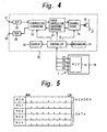
- the controller 15 controls all operations of the VTR 10, and may be constituted by a plurality of microcomputers, such as, a mechanism control microcomputer, a signal processing microcomputer, a mode processing microcomputer, an MIC microcomputer and the like.
- a video signal from an input terminal 21 is converted to a digital signal by an A/D converter 22 and is supplied to a compressing/expanding circuit 23.
- a digital component signal is divided into blocks by the compressing/expanding circuit 23 and is compressed by a DCT and variable length encoding.
- the resulting signal is error correction encoded by an error correction and coding/decoding circuit 24.
- the resultant signal is modulated by a channel coder 25 and the compressed digital video signal is recorded on a magnetic tape 27 by a head or heads 26.
- the signal recorded on the magnetic tape 27 is reproduced by the head or heads 26 and then is demodulated by the channel coder 25 and supplied to the error correction encoding/decoding circuit 24.
- An error correcting process is executed by the error correction encoding/decoding circuit 24, and the resulting output therefrom is supplied to the compressing/expanding circuit 23.
- a variable length code is decoded by the compressing/expanding circuit 23 and is subjected to an inverted DCT so that it is returned to the form of the digital data before compression.
- An output of the compressing/expanding circuit 23 is supplied to a D/A converter 28 in which the digital video signal is converted to an analog video signal which is output at a terminal 29.
- a display signal is generated by a display circuit 32 in response to a suitable signal from the controller 15, and such display signal can provide a corresponding visual signal or alarm, for example, by application of the display signal to an LED or the like.
- the controller 15 causes ejecting of the cleaning cassette, and thereby prevents overlong use of the cleaning cassette with consequent damage to the head or heads.
- the MIC microcomputer of the controller 15 in the digital VTR 10 and the MTC 12 of the cleaning cassette are connected through the terminals P1-P4.
- the terminal P1 serves as a power source terminal
- the terminal P2 as a serial data terminal
- the terminal P3 serves as a serial clock terminal
- the terminal P4 serves as a ground terminal.
- Information or data in the MIC 12 is thus supplied to the controller 15 which, from such information, determines the tape thickness and the tape type.
- the controller 15 also determines, from information contained in the MIC 12, an optimum cleaning time for each use of the cassette 1B and the number of times the cassette may be used for each cleaning operation with the respective cleaning cassette.
- the controller 15 detects from information in the MIC 12 the total number of times the respective cleaning cassette has been used and the total accumulated cleaning time or usage of the respective cleaning cassette.
- the illustrated pack structure is commonly employed for subcode data, AUX data and MIC data and is usually comprised of 5 bytes PC0-PC4.
- One byte PC0 is a header, and data is arranged in the subsequent four bytes PC1-PC4.
- the data extracted from the MIC 12 can be processed by circuits commonly employed for processing subcode data, AUX data and MIC data in the controller 15.
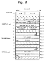
- Fig. 6 shows the data structure of an MIC provided in an ordinary video cassette
- Fig. 7 similarly shows the data structure of the MIC 12 provided in the cleaning cassette 1B embodying this invention.
- the fundamental data structures are the same in the MIC in the ordinary video cassette (Fig. 6) and in the cleaning cassette 1B embodying this invention (Fig. 7).
- additional information that is peculiar to the cleaning cassette is also stored in the MIC 12.
- Figs. 6 and 7 respectively, in both the case of the ordinary video cassette and the case of the cleaning cassette, three bits indicated at APM (Application ID of MIC) and five bits indicated at BCID (Basic Cassette ID) are provided at the head address 0 in the main area.
- the APM specifies the data structure of the MIC
- the BCID is basic cassette ID which has the same contents as were described above for the ID board 11 of the cassette 1A which is without an MIC.
- the tape thickness, tape type and grade of tape can be identified from the data written in the BCID. Further, from the bits of the BCID concerned with the tape type, it can be determined whether or not the tape is a cleaning tape.
- a space 1 is provided in the cassette ID pack. Since an item regarding such space 1 is unnecessary in the MIC of the cleaning cassette, the number (TPCN) indicating the total possible number of times the cleaning cassette can be used is indicated in units, tens and hundreds at the portions PC2 and PC3 of the cassette ID pack of the MIC in the cleaning cassette, as shown on Fig. 7.
- PC4 in the tape length pack is set to "all 1" and is empty.
- the optimum cleaning time for each time the cleaning cassette is used is indicated in tens and units of seconds at PC4 of the tape length pack.
- the title end pack of the MIC has a header different from that used in the ordinary video cassette. More specifically, as shown in Fig. 6, in the case of the ordinary video cassette, PC0 of the title end pack indicates "1Fh" (in which h denotes the hexadecimal notation). However, as shown in Fig. 7, in the case of the cleaning cassette, PC0 of the title end pack indicates "1Eh". In the case of the normal video cassette (Fig. 6), an absolute track number is stored in the title end pack which has "1Fh" as its header. On the contrary, as shown in Fig.
- the number of times (PCNC) the cleaning cassette may be used in one cleaning operation is stored in units and tens at PC1, and the total accumulated cleaning time or use of the cleaning cassette is stored in units and tens of seconds, minutes and hours at PC2, PC3 and PC4.
- whether the loaded cassette is an ordinary video cassette or a cleaning cassette can be determined by checking whether or not the indication of the tape type in the BCID is set to "01" or by checking whether the value of address 11, that is, the header of the title end pack, is equal to "1Fh" or "1Eh".
- the maker's optional area of the MIC can also be used for storing unique information regarding the cleaning cassette.
- a cleaning tape pack may be provided in the optional area for indicating at PC1 and PC2, in units, tens and hundreds, the total number of times that the cleaning cassette has been used (TCN), for indicating at at PC2 and PC3, in units, tens and hundreds, the total possible number of times the cassette can be used for cleaning (TPCN), and for indicating, at PC4, in units and tens of seconds, the maximum cleaning use of the cleaning cassette at PC4.
- a total cleaning time pack may be provided in the maker's optional area for indicating, at PC1, in units and tens, the PCNC, that is, the permissible number of times the cleaning cassette can be used for each cleaning operation. Further, as shown in Fig. 9B, at PC2, PC3 and PC4 of the optional area of the MIC, there may be indicated in units and tens of seconds, minutes and hours, the total amount of time that the associated cleaning cassette may be used.
- the operating program is initiated in response to the insertion of a video cassette into the VTR and, in response to such initiation of the program, a check is performed in step S1 to determined if the loaded cassette is a cassette 1A provided with an ID board 11 or a cassette 1B having an MIC 12.
- the tape type is judged in step S2 from the information in the associated ID board 11. More specifically, the information as to the type of tape is derived from the resistance value of the resistor R2 connected to the terminal P2.
- step S2 When it is determined in step S2 that the loaded cassette is an ordinary video cassette, ordinary VTR operations, such as, recording or reproducing operations as previously described, are executed in step S3. On the other hand, if it is judged in step S2 that the loaded cassette is a cleaning cassette, then it is determined in step S4 whether or not the VTR has been set to its ejecting mode. If it is determined in step S4 that the VTR is set to its ejecting mode, the program proceeds to step S5 in which the cleaning cassette is ejected. On the other hand, if it is determined in step S4 that the VTR is not set in its ejecting mode, then it is checked in step S6 whether or not the VTR has been set to its recording or reproducing mode.
- step S6 If the VTR is not set to its recording or reproducing mode, the routine is returned from step S6 to step S4. However, if the VTR is found to be set in its recording or reproducing mode in step S6, advancement or running of the cleaning tape is initiated and counting of the tape running time is started in step S7.
- a suitable warning signal is generated in step S8, for example, corresponding to the message "during cleaning" which is visually displayed on the display 32.
- a check is performed in step S9 to determined whether or not a specified time has elapsed. Such specified time is set to the permissible cleaning time for one use of the standard cleaning cassette, for example, a period of ten seconds. After the elapse of the specified time, the message or legend, "cleaning is finished” is generated in step S10 and is displayed on the display 32, whereupon, the cleaning cassette is ejected in step S5.
- step S1 when a cleaning cassette without an MIC is loaded into the VTR, a check is performed in step S1 to see if the loaded cassette is a cleaning cassette or not based on the information contained in the ID board. If the loaded cassette is a cleaning cassette without an MIC, after the elapse of the specified permissible cleaning time, the cleaning cassette is ejected in the step S5. Thus, accidental use of the cleaning cassette for a long time, and consequent damage to the head or heads can be prevented.
- step S1 If it is judged in step S1 that the loaded cassette is a cassette having an MIC, the program proceeds to the routine shown on Fig. 11 where, in step S11, the tape type is judged from the information contained in the MIC. If it is judged in step S11 that the tape type does not indicate a cleaning cassette, that is, if an ordinary video tape cassette with an MIC has been loaded in the VTR, the routine returns to step S3 in Fig. 10 and ordinary operations of the VTR are executed.
- step S11 if it is judged in step S11 that the tape type shown in the MIC indicates the presence of a cleaning cassette, a check is made in step S12 (Fig. 11) to determine whether or not information on the cleaning cassette also appears in the optional area.
- step S12 Fig. 11
- the total number of possible cleaning times is obtained in step S13 by dividing the indicated total possible accumulated cleaning time by the indicated permissible cleaning time for each use of the cleaning cassette.
- step S14 the calculated total number of possible cleaning times is read along with the information obtained from the main area of the MIC and which indicates the tape length, the permissible time for one use of the cleaning cassette, the number of times the cleaning cassette may be used for one cleaning operation, the total accumulated cleaning time and the total possible accumulated cleaning time.
- the information on the total number of possible cleaning times TPNC
- step S12 the information on the characteristics of the cleaning cassette also exists in the optional area, the program proceeds directly from step S12 to step S14 and the data mentioned previously as being obtained in that step is read.
- step S14 information on the length of the tape, the permissible time for each use of the cleaning cassette, the permissible number of times the cleaning cassette may be used for each cleaning operation, the total possible number of cleaning times, the total accumulated number of times the cleaning cassette has been used, and the total possible accumulated cleaning time are fetched.
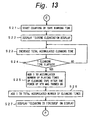
- step S14 the program proceeds to step S15 on Fig. 12 where a check is performed to determine whether or not the VTR has been set to its ejecting mode. If it is found in step S15 that the VTR has been set in its ejecting mode, the program returns to step S5 (Fig. 10) and the cassette is ejected.
- step S15 If it is determined in step S15 that the VTR is not set in its ejecting mode, a check is performed in step S16 to determine if the VTR has been set in its reproducing or recording mode. If the VTR is found not to be set in its recording or reproducing mode, the processing routine is returned to S15. If the VTR is found to be set in its reproducing or recording mode in step S16, the program proceeds to step S17 where it is determined whether or not the number of times the cleaning cassette has been used after the VTR was turned ON has exceeded the possible number of times the cleaning cassette may be used for each cleaning operation.
- step S17 If the number of times the cleaning cassette has been used after turning ON the VTR is found in step S17 to exceed the permissible number of cleaning times for a cleaning operation, the legend "Danger! No more cleaning" is displayed at the display 32 in step S18. Further, the program returns from step S18 to step S5 and the cleaning cassette is ejected.
- step S17 So long as the number of times the cleaning cassette has been used after turning ON the power to the VTR does not exceed the permissible number of cleaning times for one cleaning operation, the program proceeds from step S17 to S19 in which it is determined whether or not the total accumulated number of cleaning times exceeds the permissible total accumulated number of cleaning times. If it is found, in step S19, that the total accumulated number of cleaning times exceeds the permissible total accumulated number of cleaning times, the program proceeds to step S20 in which the legion "Life of this cleaning cassette is over" is displayed by display 32. The program returns from step S20 to step S5 in which the cleaning cassette is ejected.
- step S21 counting of the tape running time is started in step S21, the legend "During cleaning” is made to appear at display 32 in step S22, and the total accumulated cleaning time is progressively increased in step S23.
- step S24 A continuing check is performed in step S24 to determined whether or not the permissible cleaning time for one use of the cleaning cassette has elapsed. So long as the cleaning time does not exceed the permissible cleaning time for one use of the cleaning cassette, the processing routine is returned to step S23 and the total accumulated cleaning time is increased progressively. However, when the permissible cleaning time for one use of the cleaning cassette has been found to have elapsed in step S24, the accumulated number of times the cleaning cassette has been used since turning ON the VTR is increased by "1" in step S25, and the total accumulated number of times the cleaning cassette has been used is also increased by 1 in step S26. The program proceeds from step 26 to 27 in which the legend "Cleaning is finished" is displayed on the display 32 and the program is returned to step S5 in which the cleaning cassette is ejected.
- the cassette loaded into the VTR has an MIC
- a check is made of the data in the MIC to determine therefrom whether or not the loaded cassette is a cleaning cassette. If the loaded cassette is a cleaning cassette the optimum cleaning time for each use of the cleaning cassette is obtained from data in the MIC. During a use of the cleaning cassette, if the optimum time of such use elapses, the cleaning cassette is ejected from the VTR. Further, during each use of the cleaning cassette, a check is performed to determine if the number of times the cleaning cassette has been used since the turning ON of the VTR exceeds the permissible number of such times of use for each cleaning operation, as also indicated by data in the MIC.
- the cleaning cassette is used an excessive number of times during a cleaning operation, that is, if the number of times the cleaning cassette is used after the turning ON of the VTR exceeds the permissible total number of times the cleaning cassette may be used for each cleaning operation, a suitable warning is displayed and the cleaning cassette is ejected from the VTR. Moreover, if the total accumulated number of times the cleaning cassette has been used is found to exceed the permissible total number of times the cleaning cassette may be used, as indicated by information in the MIC, a suitable warning is also displayed, and the cleaning cassette, having no further useful life, is ejected from the VTR. Thus, accidental use of a cleaning cassette for a long time, or when the useful life of the cassette has elapsed, is automatically avoided and consequent damage to the head or heads of the VTR can be prevented.
- the residual amount of the cleaning tape may be calculated by the controller 15 from information acquired from the MIC 12, whereupon the residual amount of the cleaning tape can be indicated by display 32.
- the residual amount of the cleaning cassette, at any time can be calculated as follows:
- the total accumulated cleaning time can be obtained by multiplying the cleaning time for one use of the cleaning cassette by the total accumulated number of times the cassette has been used.
- the material employed for the cleaning tape in a cleaning cassette intended for an industrial use VTR differs from the cleaning tape in the cleaning cassette intended for a business use VTR and for a data streamer of a computer. Therefore, it is necessary to use such cleaning cassettes with the magnetic recording and reproducing apparatuses for which they are intended.
- the various kinds of cleaning cassettes can be identified by respective combinations of the tape grade and the tape type and in those cases where the cleaning cassette has an ID board, as on Fig. 3. In those cases where the cleaning cassettes have MICs, the kinds of cleaning cassettes can be identified by similar combinations of the tape grade and the tape type read from the respective BCID (Fig. 8) in a manner similar to the reading of such information from the ID board.
- a loaded cleaning cassette is a cleaning cassette for an industrial-use VTR, a cleaning cassette for a business-use VPR, or a cleaning cassette for the data streamer of a computer.
- the controller 15 of such apparatus may respond thereto by causing the display 32 to provide a visual or other warning, and the controller 15 may further cause the mechanism 31 to eject the inappropriate cleaning cassette.
- display 32 may be accompanied or replaced by suitably distinctive audible alarms for alerting the user to the corresponding conditions
- the invention has been specifically described as applied to a VTR of the type in which a digital video signal is compressed prior to recording.
- the invention is not limited to use with a VTR of such type, but can also be applied to other recording and reproducing apparatuses.
- the invention can also be applied to an analog 8mm VTR, in which case five detection holes are selectively formed in the bottom surface of each cassette for the 8mm VTR for identifying the tape type (MP, high-band MP or high-band ME) and the tape thickness (13 ⁇ mm, 10 ⁇ mm). Whether the loaded cassette is a cleaning cassette or not can be identified by selectively using the detection holes, of which two are reserved.
Landscapes
- Management Or Editing Of Information On Record Carriers (AREA)
- Signal Processing For Digital Recording And Reproducing (AREA)
- Automatic Disk Changers (AREA)
Claims (5)
- Appareil d'enregistrement et de reproduction magnétique (10) pour une utilisation avec une cassette normale qui contient une bande d'enregistrement et de reproduction ou une cassette de nettoyage (2) qui contient une bande de nettoyage chargée dedans, ledit appareil comprenant :caractérisé en ce que :un moyen de discrimination (15) pour déterminer si une cassette qui est chargée à l'intérieur de l'appareil est une cassette normale ou une cassette de nettoyage (1) et s'il s'agit d'une cassette de nettoyage, pour déterminer le type de la cassette de nettoyage ; etun moyen de commande (15) pour commander des opérations de l'appareil (10) de telle sorte que, lorsque ledit moyen de discrimination (15) détermine que ladite cassette qui est chargée à l'intérieur de l'appareil est une cassette de nettoyage, l'opération de nettoyage soit réalisée conformément au type de ladite cassette de nettoyage (1) qui correspond au type dudit appareil d'enregistrement et de reproduction magnétique (10),ledit moyen de discrimination (15) est agencé en fonctionnement pour détecter des données qui sont stockées dans un moyen de mémoire (MIC, 11) lorsqu'il est connecté à des bornes (P) qui sont accessibles par ledit moyen de discrimination (15) depuis l'extérieur de chaque dite cassette respective via des signaux électriques et pour déterminer à partir desdites données stockées si la cassette qui est chargée à l'intérieur dudit appareil d'enregistrement et de reproduction est la cassette normale ou la cassette de nettoyage, le type de la cassette de nettoyage, et pour déterminer à partir desdites données stockées un premier temps prédéterminé pendant lequel la cassette de nettoyage respective peut être utilisée pendant chacune de ses utilisations, le nombre de fois que la cassette de nettoyage respective peut être utilisée pendant une seule opération de nettoyage et un temps de nettoyage cumulé total pendant lequel ladite cassette de nettoyage respective a été utilisée et un temps de nettoyage possible total pendant lequel ladite cassette de nettoyage respective peut être utilisée ; etledit moyen de commande (15) répond auxdites données pour interrompre une opération de nettoyage au moyen de ladite cassette de nettoyage respective lorsque cette dernière a été en utilisation pendant ledit premier temps prédéterminé, lorsque ledit nombre de fois que la cassette de nettoyage respective peut être utilisée pendant ladite une seule opération de nettoyage est excédé ou lorsque ledit temps de nettoyage cumulé total pendant lequel ladite cassette de nettoyage respective a été utilisée excède ledit temps de nettoyage possible total pour ladite cassette de nettoyage respective.
- Appareil d'enregistrement et de reproduction magnétique (10) selon la revendication 1, dans lequel ledit moyen de mémoire de chaque cassette respective inclut une mémoire à semiconducteur (MIC), lesdites données étant stockées en tant que données numériques respectives dans ladite mémoire et ledit moyen de discrimination est agencé en fonctionnement pour détecter lesdites données numériques qui sont représentées en tant que dits signaux électriques en appliquant de l'énergie électrique sur les bornes de chaque dite cassette respective.
- Appareil d'enregistrement et de reproduction magnétique selon la revendication 1, dans lequel ledit moyen de mémoire de chaque dite cassette respective inclut une carte d'identification ou ID (11) et lesdits signaux électriques sont des valeurs de tension qui sont produites par ledit moyen de discrimination à partir de ladite carte ID.
- Cassette de nettoyage (1) pour une utilisation d'un type respectif d'un appareil d'enregistrement et de reproduction magnétique (10) à l'intérieur duquel une cassette à bande normale est chargée lors de la réalisation d'opérations d'enregistrement et de reproduction, ladite cassette de nettoyage (1) comprenant :caractérisée en ce que ladite cassette de nettoyage comprend en outre :un boítier de cassette (2) qui est configuré pour permettre le chargement de la cassette de nettoyage (1) à l'intérieur du type respectif d'appareil d'enregistrement et de reproduction magnétique (10) à la place de ladite cassette normale ;un moyen de bobines (3a, 3b) dans ledit boítier de cassette (2) ;une bande de nettoyage qui est enroulée autour dudit moyen de bobines (3a, 3b),
un moyen de mémoire (MIC, 11) qui est connecté à des bornes (P) qui sont accessibles depuis l"extérieur dudit boítier de cassette, des données stockées dans ledit moyen de mémoire et accessibles par ledit appareil d'enregistrement et de reproduction magnétique à partir desdites bornes (P) indiquant que la cassette est une bande de nettoyage qui est enroulée autour dudit moyen de bobines, un type de ladite bande de nettoyage et indiquant un temps optimum pour chaque utilisation de ladite bande de nettoyage, un nombre maximum d'utilisations de ladite bande de nettoyage pour chaque opération de nettoyage, un temps cumulé total d'utilisation de ladite bande de nettoyage qui est autorisé et un temps cumulé total pendant lequel ladite bande de nettoyage a été utilisée. - Cassette de nettoyage selon la revendication 4, dans laquelle ledit moyen de mémoire est une mémoire à semiconducteur (MIC) et lesdites données sont stockées en tant que données numériques.
Applications Claiming Priority (3)
| Application Number | Priority Date | Filing Date | Title |
|---|---|---|---|
| JP6337841A JPH08180337A (ja) | 1994-12-27 | 1994-12-27 | 磁気記録再生装置及びクリーニングカセット |
| JP33784194 | 1994-12-27 | ||
| JP337841/94 | 1994-12-27 |
Publications (3)
| Publication Number | Publication Date |
|---|---|
| EP0720163A2 EP0720163A2 (fr) | 1996-07-03 |
| EP0720163A3 EP0720163A3 (fr) | 1997-06-11 |
| EP0720163B1 true EP0720163B1 (fr) | 2001-11-21 |
Family
ID=18312482
Family Applications (1)
| Application Number | Title | Priority Date | Filing Date |
|---|---|---|---|
| EP95309475A Expired - Lifetime EP0720163B1 (fr) | 1994-12-27 | 1995-12-27 | Appareil d'enregistrement et de reproduction magnétique et cassette de nettoyage pour cet appareil |
Country Status (8)
| Country | Link |
|---|---|
| US (3) | US5726817A (fr) |
| EP (1) | EP0720163B1 (fr) |
| JP (1) | JPH08180337A (fr) |
| KR (1) | KR100394514B1 (fr) |
| CN (1) | CN1078728C (fr) |
| DE (1) | DE69524047T2 (fr) |
| MY (1) | MY113415A (fr) |
| TW (1) | TW436762B (fr) |
Families Citing this family (12)
| Publication number | Priority date | Publication date | Assignee | Title |
|---|---|---|---|---|
| JPH0798935A (ja) * | 1993-09-29 | 1995-04-11 | Toshiba Corp | 情報信号記録再生装置 |
| JPH08180337A (ja) * | 1994-12-27 | 1996-07-12 | Sony Corp | 磁気記録再生装置及びクリーニングカセット |
| US6043948A (en) * | 1995-11-08 | 2000-03-28 | Sony Corporation | Information recording and reproducing apparatus |
| GB2335301A (en) * | 1998-03-10 | 1999-09-15 | Hewlett Packard Co | Tape drive cleaning cartridge with data tape leader incorporating memory and communications circuitry |
| US6285518B1 (en) * | 1998-08-26 | 2001-09-04 | Exabyte Corporation | Life/wear monitoring for magnetic tape |
| JP3482886B2 (ja) * | 1998-09-29 | 2004-01-06 | 松下電器産業株式会社 | 磁気記録再生装置 |
| WO2000038188A1 (fr) * | 1998-12-18 | 2000-06-29 | Sony Corporation | Support d'enregistrement, lecteur de bande et procede d'identification du type de support d'enregistrement |
| JP2000331451A (ja) | 1999-05-18 | 2000-11-30 | Fuji Photo Film Co Ltd | 磁気テープカセット |
| JP2002319113A (ja) * | 2001-04-23 | 2002-10-31 | Sony Corp | 磁気記録再生装置、クリーニングカセット及びクリーニング時間の設定方法 |
| US7075874B2 (en) * | 2001-07-17 | 2006-07-11 | Hewlett-Packard Development Company, L.P. | Data storage device monitoring system, method and removable data carrier use with data storage systems |
| US6982846B2 (en) * | 2003-05-19 | 2006-01-03 | International Business Machines Corporation | Tamper resistant write once recording of a data storage cartridge having rewritable media |
| US9666217B1 (en) * | 2016-02-18 | 2017-05-30 | Dell Products L.P. | Systems and methods for dynamically cleaning read/write head |
Family Cites Families (17)
| Publication number | Priority date | Publication date | Assignee | Title |
|---|---|---|---|---|
| US3711654A (en) * | 1969-04-30 | 1973-01-16 | Canon Kk | Magnetic recording and reproducing device for use with an endless recording medium with means for indicating a recordable state with-in one cycle of the endless recording medium |
| BE871690R (fr) * | 1978-10-27 | 1979-02-15 | Staar Sa | Dispositif de memorisation de la position instantanee d'une bande magnetique contenue dans une cassette |
| DE8610911U1 (de) * | 1986-04-21 | 1986-06-05 | Nixdorf Computer Ag, 4790 Paderborn | Reinigungskassette |
| EP0265167B1 (fr) * | 1986-10-15 | 1997-01-02 | Pioneer Electronic Corporation | Lecteur de disques avec magasin de disques |
| US4984120A (en) * | 1988-01-27 | 1991-01-08 | Tdk Corporation | Cleaning cassette for a video cassette tape deck |
| DE3901666A1 (de) * | 1988-11-25 | 1989-06-15 | Gigatape Systeme Fuer Datensic | Verfahren zur magnetkopfreinigung und vorrichtung zur durchfuehrung des verfahrens |
| AT391220B (de) * | 1988-12-14 | 1990-09-10 | Philips Nv | Aufzeichnungs- und/oder wiedergabesystem und kassette fuer ein solches system |
| US5088082A (en) * | 1989-08-09 | 1992-02-11 | Hitachi Video Engineering, Inc. | Dust removing system for optical disk device |
| GB2250627B (en) * | 1990-11-22 | 1994-09-07 | Gold Star Co | Head cleaner for VCR and automatic head cleaning apparatus and method |
| BR9206393A (pt) * | 1991-08-19 | 1995-06-20 | Henry C Yuen | Diretório de programas para um cassette de fita de vídeo |
| EP0533002A1 (fr) * | 1991-09-19 | 1993-03-24 | Deutsche Thomson-Brandt Gmbh | Cassette pour appareil d'enregistrement |
| EP0557571A1 (fr) * | 1992-02-24 | 1993-09-01 | Tandberg Data A/S | Cassette de nettoyage adaptée à un fonctionnement automatique |
| US5390870A (en) * | 1992-06-01 | 1995-02-21 | Sony Corporation | Recording medium cassette and a recording/reproducing apparatus |
| US5434721A (en) * | 1992-06-02 | 1995-07-18 | Sony Corporation | Recording/reproducing apparatus for recording/reproducing information to and/or from a plurality of types of recording medium cassettes |
| JP3106738B2 (ja) * | 1992-10-21 | 2000-11-06 | ソニー株式会社 | 磁気テープ記録再生装置および磁気テープユニット |
| US5541794A (en) * | 1993-05-25 | 1996-07-30 | Griffen; Edward E. | Magnetic tape recording head cleaning apparatus |
| JPH08180337A (ja) * | 1994-12-27 | 1996-07-12 | Sony Corp | 磁気記録再生装置及びクリーニングカセット |
-
1994
- 1994-12-27 JP JP6337841A patent/JPH08180337A/ja active Pending
-
1995
- 1995-12-22 US US08/577,327 patent/US5726817A/en not_active Expired - Fee Related
- 1995-12-26 MY MYPI95004079A patent/MY113415A/en unknown
- 1995-12-27 KR KR1019950072162A patent/KR100394514B1/ko not_active IP Right Cessation
- 1995-12-27 EP EP95309475A patent/EP0720163B1/fr not_active Expired - Lifetime
- 1995-12-27 DE DE69524047T patent/DE69524047T2/de not_active Expired - Fee Related
- 1995-12-27 CN CN95121621A patent/CN1078728C/zh not_active Expired - Fee Related
-
1996
- 1996-01-11 TW TW085100302A patent/TW436762B/zh not_active IP Right Cessation
-
1997
- 1997-04-24 US US08/845,514 patent/US5854728A/en not_active Expired - Fee Related
- 1997-09-29 US US08/939,875 patent/US5901007A/en not_active Expired - Fee Related
Also Published As
| Publication number | Publication date |
|---|---|
| CN1131786A (zh) | 1996-09-25 |
| MY113415A (en) | 2002-02-28 |
| US5726817A (en) | 1998-03-10 |
| KR100394514B1 (ko) | 2003-11-14 |
| US5901007A (en) | 1999-05-04 |
| US5854728A (en) | 1998-12-29 |
| DE69524047D1 (de) | 2002-01-03 |
| CN1078728C (zh) | 2002-01-30 |
| TW436762B (en) | 2001-05-28 |
| JPH08180337A (ja) | 1996-07-12 |
| EP0720163A2 (fr) | 1996-07-03 |
| DE69524047T2 (de) | 2002-07-18 |
| EP0720163A3 (fr) | 1997-06-11 |
Similar Documents
| Publication | Publication Date | Title |
|---|---|---|
| EP0720163B1 (fr) | Appareil d'enregistrement et de reproduction magnétique et cassette de nettoyage pour cet appareil | |
| KR970000920B1 (ko) | 테이프 카세트 | |
| EP0594438B1 (fr) | Appareil d'enregistrement des données avec un dispositif à reconnaítre la bande magnétique appliquée | |
| US5136317A (en) | Camera having a magnetic head, film means loadable to the same and a camera system | |
| US5943468A (en) | Apparatus for reproducing data from a memory device integrally provided with a plurality of kinds of recording media | |
| EP0677847B1 (fr) | Etiquette pour cassette de données | |
| EP0430262A2 (fr) | Caméra pourvue d'une tête magnétique, unité de film associée et système de caméra | |
| JP2692248B2 (ja) | 記録再生装置 | |
| JP3834859B2 (ja) | クリーニングカセット及び磁気記録再生装置 | |
| JP2828088B2 (ja) | カセット | |
| JPH0235618A (ja) | 磁気記録再生装置 | |
| JP4048613B2 (ja) | テープカセット排出検出方法、ならびに、記録または再生装置 | |
| JP2773538B2 (ja) | 電子機器 | |
| JPH1011835A (ja) | 記録装置 | |
| JPH10208221A (ja) | カセットチェンジャー | |
| EP0512628A2 (fr) | Système d'enregistrement/de lecture magnétique de signaux | |
| JPS60251542A (ja) | 磁気記録再生装置 | |
| JPS63166085A (ja) | テ−プカセツト | |
| JPS63164084A (ja) | テ−プカセツト | |
| JPH1011836A (ja) | 記録装置 | |
| JPH10112161A (ja) | 記録媒体装置 | |
| KR19990056424A (ko) | 비디오 카세트 레코더의 정전 및 정전 복구시 구동방법 | |
| JPH09305937A (ja) | 記録又は再生装置 | |
| JP2002319113A (ja) | 磁気記録再生装置、クリーニングカセット及びクリーニング時間の設定方法 | |
| JPH07122033A (ja) | カセット及び電子機器 |
Legal Events
| Date | Code | Title | Description |
|---|---|---|---|
| PUAI | Public reference made under article 153(3) epc to a published international application that has entered the european phase |
Free format text: ORIGINAL CODE: 0009012 |
|
| AK | Designated contracting states |
Kind code of ref document: A2 Designated state(s): DE FR GB |
|
| PUAL | Search report despatched |
Free format text: ORIGINAL CODE: 0009013 |
|
| AK | Designated contracting states |
Kind code of ref document: A3 Designated state(s): DE FR GB |
|
| 17P | Request for examination filed |
Effective date: 19971016 |
|
| 17Q | First examination report despatched |
Effective date: 19990722 |
|
| GRAG | Despatch of communication of intention to grant |
Free format text: ORIGINAL CODE: EPIDOS AGRA |
|
| GRAH | Despatch of communication of intention to grant a patent |
Free format text: ORIGINAL CODE: EPIDOS IGRA |
|
| GRAH | Despatch of communication of intention to grant a patent |
Free format text: ORIGINAL CODE: EPIDOS IGRA |
|
| GRAA | (expected) grant |
Free format text: ORIGINAL CODE: 0009210 |
|
| AK | Designated contracting states |
Kind code of ref document: B1 Designated state(s): DE FR GB |
|
| REG | Reference to a national code |
Ref country code: GB Ref legal event code: IF02 |
|
| REF | Corresponds to: |
Ref document number: 69524047 Country of ref document: DE Date of ref document: 20020103 |
|
| ET | Fr: translation filed | ||
| PLBE | No opposition filed within time limit |
Free format text: ORIGINAL CODE: 0009261 |
|
| STAA | Information on the status of an ep patent application or granted ep patent |
Free format text: STATUS: NO OPPOSITION FILED WITHIN TIME LIMIT |
|
| 26N | No opposition filed | ||
| PGFP | Annual fee paid to national office [announced via postgrant information from national office to epo] |
Ref country code: FR Payment date: 20081212 Year of fee payment: 14 |
|
| PGFP | Annual fee paid to national office [announced via postgrant information from national office to epo] |
Ref country code: DE Payment date: 20081229 Year of fee payment: 14 |
|
| PGFP | Annual fee paid to national office [announced via postgrant information from national office to epo] |
Ref country code: GB Payment date: 20081224 Year of fee payment: 14 |
|
| GBPC | Gb: european patent ceased through non-payment of renewal fee |
Effective date: 20091227 |
|
| REG | Reference to a national code |
Ref country code: FR Ref legal event code: ST Effective date: 20100831 |
|
| PG25 | Lapsed in a contracting state [announced via postgrant information from national office to epo] |
Ref country code: FR Free format text: LAPSE BECAUSE OF NON-PAYMENT OF DUE FEES Effective date: 20091231 |
|
| PG25 | Lapsed in a contracting state [announced via postgrant information from national office to epo] |
Ref country code: DE Free format text: LAPSE BECAUSE OF NON-PAYMENT OF DUE FEES Effective date: 20100701 |
|
| PG25 | Lapsed in a contracting state [announced via postgrant information from national office to epo] |
Ref country code: GB Free format text: LAPSE BECAUSE OF NON-PAYMENT OF DUE FEES Effective date: 20091227 |