EP0718130B1 - Méthode de modulation d'un ensemble modulaire de liaison élastique formant attache d'amortisseur et bloc filtrant - Google Patents
Méthode de modulation d'un ensemble modulaire de liaison élastique formant attache d'amortisseur et bloc filtrant Download PDFInfo
- Publication number
- EP0718130B1 EP0718130B1 EP94402956A EP94402956A EP0718130B1 EP 0718130 B1 EP0718130 B1 EP 0718130B1 EP 94402956 A EP94402956 A EP 94402956A EP 94402956 A EP94402956 A EP 94402956A EP 0718130 B1 EP0718130 B1 EP 0718130B1
- Authority
- EP
- European Patent Office
- Prior art keywords
- annular
- assembly
- elastic connection
- fact
- elastomeric
- Prior art date
- Legal status (The legal status is an assumption and is not a legal conclusion. Google has not performed a legal analysis and makes no representation as to the accuracy of the status listed.)
- Expired - Lifetime
Links
- 230000035939 shock Effects 0.000 title claims description 51
- 239000006096 absorbing agent Substances 0.000 title claims description 42
- 238000000034 method Methods 0.000 title claims description 19
- 238000001914 filtration Methods 0.000 title claims description 14
- 238000011049 filling Methods 0.000 claims description 85
- 239000012530 fluid Substances 0.000 claims description 66
- 230000002787 reinforcement Effects 0.000 claims description 44
- 230000000694 effects Effects 0.000 claims description 26
- 230000003068 static effect Effects 0.000 claims description 25
- 239000011345 viscous material Substances 0.000 claims description 13
- 239000000725 suspension Substances 0.000 claims description 10
- 239000007791 liquid phase Substances 0.000 claims description 8
- 150000001875 compounds Chemical class 0.000 claims description 2
- 230000007246 mechanism Effects 0.000 claims description 2
- 239000007792 gaseous phase Substances 0.000 claims 2
- 239000000203 mixture Substances 0.000 description 49
- 239000007788 liquid Substances 0.000 description 47
- 239000007789 gas Substances 0.000 description 37
- 238000007789 sealing Methods 0.000 description 13
- 238000013016 damping Methods 0.000 description 11
- 238000004891 communication Methods 0.000 description 10
- 238000006073 displacement reaction Methods 0.000 description 10
- 210000002105 tongue Anatomy 0.000 description 10
- 238000007726 management method Methods 0.000 description 8
- 239000000470 constituent Substances 0.000 description 7
- 229920001971 elastomer Polymers 0.000 description 7
- 238000010586 diagram Methods 0.000 description 6
- 230000006835 compression Effects 0.000 description 5
- 238000007906 compression Methods 0.000 description 5
- 239000000806 elastomer Substances 0.000 description 5
- 230000002829 reductive effect Effects 0.000 description 5
- 230000008901 benefit Effects 0.000 description 4
- 230000001965 increasing effect Effects 0.000 description 4
- 230000000670 limiting effect Effects 0.000 description 4
- 230000036961 partial effect Effects 0.000 description 4
- 230000008859 change Effects 0.000 description 3
- 239000000463 material Substances 0.000 description 3
- 238000002156 mixing Methods 0.000 description 3
- 230000002093 peripheral effect Effects 0.000 description 3
- 239000012071 phase Substances 0.000 description 3
- 230000000750 progressive effect Effects 0.000 description 3
- 230000009467 reduction Effects 0.000 description 3
- 238000010008 shearing Methods 0.000 description 3
- IJGRMHOSHXDMSA-UHFFFAOYSA-N Atomic nitrogen Chemical compound N#N IJGRMHOSHXDMSA-UHFFFAOYSA-N 0.000 description 2
- 230000000712 assembly Effects 0.000 description 2
- 238000000429 assembly Methods 0.000 description 2
- 239000011248 coating agent Substances 0.000 description 2
- 238000000576 coating method Methods 0.000 description 2
- 238000013461 design Methods 0.000 description 2
- 238000009826 distribution Methods 0.000 description 2
- 230000001939 inductive effect Effects 0.000 description 2
- 239000002184 metal Substances 0.000 description 2
- 238000011084 recovery Methods 0.000 description 2
- 230000000284 resting effect Effects 0.000 description 2
- 238000005096 rolling process Methods 0.000 description 2
- 238000003756 stirring Methods 0.000 description 2
- 230000009471 action Effects 0.000 description 1
- 230000006978 adaptation Effects 0.000 description 1
- 238000004458 analytical method Methods 0.000 description 1
- 238000013459 approach Methods 0.000 description 1
- 238000012550 audit Methods 0.000 description 1
- 238000005452 bending Methods 0.000 description 1
- 230000005540 biological transmission Effects 0.000 description 1
- 239000003795 chemical substances by application Substances 0.000 description 1
- 238000004132 cross linking Methods 0.000 description 1
- 238000005238 degreasing Methods 0.000 description 1
- 230000006866 deterioration Effects 0.000 description 1
- 238000009413 insulation Methods 0.000 description 1
- 238000002955 isolation Methods 0.000 description 1
- 238000004519 manufacturing process Methods 0.000 description 1
- 238000003032 molecular docking Methods 0.000 description 1
- 238000000465 moulding Methods 0.000 description 1
- 229910052757 nitrogen Inorganic materials 0.000 description 1
- 238000005457 optimization Methods 0.000 description 1
- 210000000056 organ Anatomy 0.000 description 1
- 238000003825 pressing Methods 0.000 description 1
- 238000002203 pretreatment Methods 0.000 description 1
- 238000009877 rendering Methods 0.000 description 1
- 230000004044 response Effects 0.000 description 1
- 238000010057 rubber processing Methods 0.000 description 1
- 238000000926 separation method Methods 0.000 description 1
- 238000012360 testing method Methods 0.000 description 1
- 238000012546 transfer Methods 0.000 description 1
- 230000001052 transient effect Effects 0.000 description 1
- 239000004636 vulcanized rubber Substances 0.000 description 1
Images


Classifications
-
- B—PERFORMING OPERATIONS; TRANSPORTING
- B60—VEHICLES IN GENERAL
- B60G—VEHICLE SUSPENSION ARRANGEMENTS
- B60G15/00—Resilient suspensions characterised by arrangement, location or type of combined spring and vibration damper, e.g. telescopic type
- B60G15/02—Resilient suspensions characterised by arrangement, location or type of combined spring and vibration damper, e.g. telescopic type having mechanical spring
- B60G15/06—Resilient suspensions characterised by arrangement, location or type of combined spring and vibration damper, e.g. telescopic type having mechanical spring and fluid damper
- B60G15/067—Resilient suspensions characterised by arrangement, location or type of combined spring and vibration damper, e.g. telescopic type having mechanical spring and fluid damper characterised by the mounting on the vehicle body or chassis of the spring and damper unit
-
- F—MECHANICAL ENGINEERING; LIGHTING; HEATING; WEAPONS; BLASTING
- F16—ENGINEERING ELEMENTS AND UNITS; GENERAL MEASURES FOR PRODUCING AND MAINTAINING EFFECTIVE FUNCTIONING OF MACHINES OR INSTALLATIONS; THERMAL INSULATION IN GENERAL
- F16F—SPRINGS; SHOCK-ABSORBERS; MEANS FOR DAMPING VIBRATION
- F16F13/00—Units comprising springs of the non-fluid type as well as vibration-dampers, shock-absorbers, or fluid springs
- F16F13/04—Units comprising springs of the non-fluid type as well as vibration-dampers, shock-absorbers, or fluid springs comprising both a plastics spring and a damper, e.g. a friction damper
- F16F13/06—Units comprising springs of the non-fluid type as well as vibration-dampers, shock-absorbers, or fluid springs comprising both a plastics spring and a damper, e.g. a friction damper the damper being a fluid damper, e.g. the plastics spring not forming a part of the wall of the fluid chamber of the damper
- F16F13/20—Units comprising springs of the non-fluid type as well as vibration-dampers, shock-absorbers, or fluid springs comprising both a plastics spring and a damper, e.g. a friction damper the damper being a fluid damper, e.g. the plastics spring not forming a part of the wall of the fluid chamber of the damper characterised by comprising also a pneumatic spring
-
- F—MECHANICAL ENGINEERING; LIGHTING; HEATING; WEAPONS; BLASTING
- F16—ENGINEERING ELEMENTS AND UNITS; GENERAL MEASURES FOR PRODUCING AND MAINTAINING EFFECTIVE FUNCTIONING OF MACHINES OR INSTALLATIONS; THERMAL INSULATION IN GENERAL
- F16F—SPRINGS; SHOCK-ABSORBERS; MEANS FOR DAMPING VIBRATION
- F16F13/00—Units comprising springs of the non-fluid type as well as vibration-dampers, shock-absorbers, or fluid springs
- F16F13/04—Units comprising springs of the non-fluid type as well as vibration-dampers, shock-absorbers, or fluid springs comprising both a plastics spring and a damper, e.g. a friction damper
- F16F13/06—Units comprising springs of the non-fluid type as well as vibration-dampers, shock-absorbers, or fluid springs comprising both a plastics spring and a damper, e.g. a friction damper the damper being a fluid damper, e.g. the plastics spring not forming a part of the wall of the fluid chamber of the damper
- F16F13/24—Units comprising springs of the non-fluid type as well as vibration-dampers, shock-absorbers, or fluid springs comprising both a plastics spring and a damper, e.g. a friction damper the damper being a fluid damper, e.g. the plastics spring not forming a part of the wall of the fluid chamber of the damper the central part of the unit being supported by one element and both extremities of the unit being supported by a single other element, i.e. double acting mounting
-
- F—MECHANICAL ENGINEERING; LIGHTING; HEATING; WEAPONS; BLASTING
- F16—ENGINEERING ELEMENTS AND UNITS; GENERAL MEASURES FOR PRODUCING AND MAINTAINING EFFECTIVE FUNCTIONING OF MACHINES OR INSTALLATIONS; THERMAL INSULATION IN GENERAL
- F16F—SPRINGS; SHOCK-ABSORBERS; MEANS FOR DAMPING VIBRATION
- F16F13/00—Units comprising springs of the non-fluid type as well as vibration-dampers, shock-absorbers, or fluid springs
- F16F13/04—Units comprising springs of the non-fluid type as well as vibration-dampers, shock-absorbers, or fluid springs comprising both a plastics spring and a damper, e.g. a friction damper
- F16F13/26—Units comprising springs of the non-fluid type as well as vibration-dampers, shock-absorbers, or fluid springs comprising both a plastics spring and a damper, e.g. a friction damper characterised by adjusting or regulating devices responsive to exterior conditions
-
- F—MECHANICAL ENGINEERING; LIGHTING; HEATING; WEAPONS; BLASTING
- F16—ENGINEERING ELEMENTS AND UNITS; GENERAL MEASURES FOR PRODUCING AND MAINTAINING EFFECTIVE FUNCTIONING OF MACHINES OR INSTALLATIONS; THERMAL INSULATION IN GENERAL
- F16F—SPRINGS; SHOCK-ABSORBERS; MEANS FOR DAMPING VIBRATION
- F16F2230/00—Purpose; Design features
- F16F2230/0052—Physically guiding or influencing
- F16F2230/007—Physically guiding or influencing with, or used as an end stop or buffer; Limiting excessive axial separation
Definitions
- the invention relates to the field of elastic connections involved in suspensions, in particular vehicle wheel and engine suspensions. She is, more specifically, an application of depreciation hydraulic and / or pneumatic to said elastic connection in as a hanging clip between the rod of a vehicle shock absorber and its chassis.
- the device which is described in the document DE-A-3 034 743 from Continental combines, in one piece complex, permanent support - through a stop bearing - of the suspension spring as well as the ring elastic where the bonding force is exerted, dynamically alternating between the shock absorber rod and the support on checkout.
- the end-of-travel efforts dynamic are exerted on the fixing of the rod shock absorber, due to the presence of a stop rubber, not through the ball bearing, which carries a low variation load, because modulated exclusively by the flexibility of the spring, even in fast deflections.
- FR-A-2,563,302 from Volvo describes a device, called a leg mount pendant lamp, in which a small space allows a short free movement between stops, inside a shock absorber rod upper attachment which also carries the permanent load of the spring.
- the device assembles, in one piece single, two opposite rooms, connected by a canal liquid wound on their outside diameter, channel great length and notable section, causing an effect significant inertial, without the viscosity of the liquid which is contained acts on displacements.
- JP-A-62-56641 and JP-A-58-81240 describe a method for adjusting the rigidity of an elastic sleeve.
- the invention is therefore a method of modulating a modular link assembly elastic, forming shock absorber attachment and filter block, between the rod of a vehicle shock absorber and a structure to amortize. It consists of rigid annular reinforcements intimately linked to a connection set in elastomeric composition for delimiting a closed volume, containing a filling fluid, said assembly flexible elastic connection being rigidly linked, of a part, to the shock absorber rod via a internal lower frame and upper frame internal, on the other hand to the structure to be amortized by through at least one upper frame.
- the invention is characterized in that the closed volume is delimited by an assembly with upper annular reinforcement and / or a lower ring armature assembly, whether presents, vis-à-vis its external environment, a seal total, by fitting shutters after filling, and in that a modulation of the static characteristics and dynamic is obtained by variation of the composition filling fluid and / or the volume of said closed volume which, cooperating with the connection assembly in elastomeric composition, allows on the one hand to adapt the relative displacements of the components of the assemblies to upper and lower annular reinforcements as well as said connection assembly in elastomeric composition, on the other hand to filter vibrations according to progressive amortization requirements.
- the enclosed volume consists of a chamber single ring or a set of two chambers non-communicating ring fingers.
- the filling fluid in the enclosed volume may consist of a gas, a liquid homogeneous or a mixture of liquids, miscible or not, of different viscosities, of a liquid in the presence of a gas, viscous material or viscous material in presence of a gas.
- composition of the filling fluid allows, in effect, to modulate the static and dynamic rigidities, while its viscosity allows to modulate the function amortization.
- the closed volume can include a filling fluid management system, which is constituted either by a distributor with several positions, or, in other variant embodiments, by a direct piloting device, piloting which can be do by the stresses of the shock absorber or by those another organ participating in the movement to be amortized, constituting, in these latter cases, a modular assembly active elastic bond.
- a filling fluid management system which is constituted either by a distributor with several positions, or, in other variant embodiments, by a direct piloting device, piloting which can be do by the stresses of the shock absorber or by those another organ participating in the movement to be amortized, constituting, in these latter cases, a modular assembly active elastic bond.
- the flexible elastic connection assembly may include a stroke limitation contact consisting by end-of-travel stops, in composition elastomeric or other cushioning material, arranged on the assembly with upper annular reinforcement and / or on the lower annular reinforcement assembly.
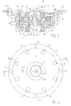
- Figure 1 is a view, in axial section, of an assembly modular elastic connection according to the invention, forming shock absorber attachment and filter block between a shock absorber (1) and a structure to be absorbed (2), such as the chassis of a vehicle, for example, Figure 2 being the top view corresponding, according to II.
- Said modular elastic connection set is one piece of revolution made up, in the illustrated variant, of a upper ring reinforcement (AS) and a intimately lower ring armature (AI) assembly linked to a composition connection set elastomeric (RE), to delimit a closed volume, comprising an upper annular chamber (11) and a lower annular chamber (12).
- AS upper ring reinforcement
- AI intimately lower ring armature
- RE composition connection set elastomeric
- the upper ring reinforcement assembly (AS) is formed of an upper frame (9) in L and of a frame internal link (4), L-shaped inverted with respect to the upper frame (9); said upper frames (9) and internal liaison (4) are intimately linked by the external face of their branches at angles (91, 41), respectively to one side of a connecting element upper elastic (15) and on one side of a intermediate elastic connection (14), both part of the connection set in composition elastomeric (RE), to form the walls of the chamber upper annular (11).
- the assembly with annular reinforcements lower is formed by a lower reinforcement (7) and of the internal connection frame (4); the frame lower (7) is linked by a face of its end (71) on one side of a lower elastic connection element (13), a partial constituent of the connection assembly in elastomeric composition (ER), to form, in combination with the internal connecting frame (4) and the element intermediate elastic connection (14) the walls of the lower annular chamber (12).
- the upper (11) and lower (12) annular chambers must present to each other and to their environment exterior completely sealed and define the volume closed which includes a filling fluid.
- the assembly thus formed is mounted blocked on the one hand on the rod (6) of the shock absorber (1), on the other hand on the structure to be amortized (2).
- the assembly with annular reinforcements lower (AI) is connected to the rod (6) of the shock absorber (1) by means of a ring (10) mounted adjusted on the end (17) of the rod (6) and provided with a collar (19) which rests on a shoulder (18) of said rod (6) and on the internal lower frame (3), this ring (10) cooperating with a nut (16) which blocks the assembly on the rod (6) by resting on the upper frame internal (5), the internal connecting frame (4) thus being tight.
- the upper ring reinforcement assembly (AS) has means for assembling its elements (20) and fixing means (21) on the structure to be damped (2).
- the assembly and fixing means (20, 21) are constituted most commonly by screws or bolts transverse, the first bringing together the reinforcements lower (7) and upper (9) which enclose the internal connection frame (4), the second allowing fixing to the vehicle.
- annular reinforcement assembly higher (AS) is achieved through a external connection reinforcement (8) whose internal face is intimately linked to the external fax machine of the intermediate elastic connection (14) and the face of which opposite comes into local support, by its ends, on the internal face of the lower frame (7).
- the lower elastic connection element (13) and the upper elastic connection element (15) have a sealing tongue (22, 23) arranged between the internal connection frame (4) on the one hand and internal lower armature (3) or internal upper armature (5) on the other hand, and the connecting element intermediate elastic (14) has two tabs sealing rings (24, 25) arranged respectively between the internal connection frame (4) on the one hand, and the corresponding lower (7) or upper (9) frame on the other hand.
- the upper annular reinforcement assembly (AS) here comprises at least one shutter (29), intended to enclose the filling fluid in the chamber upper annular (11) and mounted in the orifice filling (28) formed in the upper frame (9), like the lower annular reinforcement assembly (AI) comprises at least one shutter (27) intended to come enclose the fluid in the lower annular chamber (12) and mounted in the filling opening (26) formed in the lower frame (7).
- the filling of the closed volume can be achieved by different means, such as technique called “underwater” or by injecting the filling in the rooms by any technique appropriate, said means rendering unnecessary the presence of shutters (27,29).
- the upper annular chamber (11) consists of two half-chambers (11a, 11b) connected by a passage (11c) formed between the faces of the angled arm (91) of the armature upper (9) and the angled branch (41) of the armature internal link (4).
- This provision allows, between walls of the upper annular chamber (11), a mixing liquid, under dynamic stress caused by movements of the rod (6) of the shock absorber (1), stirring which influences both the dynamic stiffness and the damping capacity of the device.
- the operating principle of the modular set of elastic connection according to the invention is based on the transmission of the movements of the shock absorber rod (6) (1) by the internal lower frame (3), the frame of internal connection (4) and the internal upper reinforcement (5) to the connection assembly in elastomeric composition (RE) with lower elastic connection elements (13), intermediate (14) and upper (15) provide insulation of the lower annular chambers (12) and upper (11) respectively, said chambers annulars (11, 12) being devoid of communication between them and containing a filling fluid comprising at minus a material or viscous or liquid or gaseous, said gas may be air.
- the shutters (27, 29) of the annular chambers (11, 12) ensure their tightness vis-à-vis from the outside environment, by closing the orifices of filling (26, 28) which allow the introduction of the filling fluid in the closed volume.
- the upper annular chambers (11) and lower (12) are filled with air at pressure atmospheric and the device behaves, from the point of view filtering and damping vibrations, like a prior art device in which the elements of elastic connection (13, 14, 15) are stressed in pure shear.
- the resulting curve of deflections as a function of forces applied is then substantially linear and the device does not have a travel limit in extreme stress conditions.
- the modular link assembly elastic behaves like an elastic device pneumatic when the filling fluid is a gas, as a hydroelastic device when the fluid of filling is a liquid or as an elastic device hydropneumatic when the filling fluid is partially consisting of a gas and partially of a liquid.
- the modulation of the dynamic characteristics of the whole flexible elastic connection according to the invention is obtained by the action of two parameters, taken in isolation or in combination, which are the nature of the filling fluid closed volume, defining its density or viscosity, and its composition, and, more precisely, in the version hydropneumatic of the device, the volume proportion relative of gas and liquid, the distribution of said fluid filling in the two annular chambers (11, 12) may be the same or different.
- the volume closed consisting of the upper annular chamber (11) and of the lower annular chamber (12), comprises a fluid filling consisting of approximately 80% liquid in the upper annular chamber (11) and about 60% of liquid in the lower annular chamber (12), the rest of the volume of said chambers being occupied by a gas.
- the resulting force-deflection law bends notably compared to the linear deformation described previously for the device whose chambers annulars are in communication with the atmosphere, corresponding to increasing stiffening and progressive, said progressiveness being one of essential characteristics of the modular set of elastic connection.
- Figure 3 is a partial section of the modular assembly of elastic connection according to the invention whose closed volume consists of an upper annular chamber (11), and a lower annular chamber (12); in the variant shown, the two annular chambers (11 and 12) are filled with a gaseous fluid, for example air or nitrogen.
- a gaseous fluid for example air or nitrogen.
- the upper elastic connection elements (15), fitted with its sealing tongue (23), intermediate (14), provided with its two annular sealing tongues lower (24) and upper (25) and the element of lower elastic connection (13), equipped with its sealing tongue (22) have, in the rest state, that is to say in the absence of solicitation, a form substantially parallelepiped.
- AS upper ring armature
- AI upper annular reinforcement
- the relative movement of the constituents of the upper ring armature (AS) assembly and the assembly with lower annular reinforcement (AI) requires to the components of the connection assembly in composition elastomeric (RE) shear deformation leading to a substantially diamond-shaped section, characteristic of this type of deformation.
- annular chambers (11 and 12) are filled with air at atmospheric pressure since they are in communication with the outside.
- the flexible elastic connection assembly behaves then, from the point of view of filtering, as a device for the prior art in which the connecting elements elastic are stressed in pure shear, the response of the system resulting in direct proportionality efforts according to deflections.
- the modular assembly of elastic bond behaves, from the point of view of filtering in pneumatic elastic device; in this case the effect a displacement of the rod (6) of the shock absorber (1), results in displacement of the connection elements lower elastic (13), intermediate (14) and upper (15) forming the connection assembly in composition elastomeric (RE), which induces a change in volume annular chambers (11, 12).
- the annular chamber upper (11) sees, in fact, its volume then reduce that the annular chamber (12) sees its volume increase when the rod (6) of the shock absorber (1) performs a upward movement, evolution of the volume of the chambers annulars (11, 12) going in the opposite direction when the rod (6) of the shock absorber performs a movement descending.
- Figure 4 is a half section of another variant of the flexible, elastic two-chamber assembly non-communicating annulars (11, 12), in the version constituting a flexible assembly of elastic connection hydropneumatic. It illustrates the behavior under device solicitation.
- the upper annular chamber (11) is practically filled with a liquid, while the lower annular chamber (12) contains a filling consisting of a liquid and a gas.
- the liquid of the upper annular chamber (11) being, by definition, incompressible, the only role that could play said annular chamber (11) would be that of a adjustable damping according to the viscosity of the liquid, with high static rigidity, the annular chamber lower (12) playing essentially a filtering role in the downward movements of the rod (6) of the shock absorber (1).
- This version which leads to a strong dynamic stiffness in upward movements, is generally preferred a version in which both annular chambers (11, 12) contain a fluid compound filling, both liquid or material viscous and gas, even if the volume proportion of gas is weak.
- the volume of the annular chamber upper (11) is reduced under the effect of the forces of applied shear and deformation of the elements of elastic connection concerned (14,15) which take a substantially diamond-shaped section.
- the bulge of the underside of the element of intermediate elastic connection (14) can be used as the end stop, because when all of connection in elastomeric composition (RE) is deformed under the effect of significant stresses, said bulging of the underside of the element of intermediate elastic connection (14) can come in contact of the part of the lower armature (7) which forms the bottom of the lower annular chamber (12) and thus limit deformations.
- Figure 5 illustrates, on a diagram, the variation of deflections of the device as a function of the forces applied, for a flexible set of elastic connection of the type hydropneumatic, i.e. in which each of the annular chambers (11, 12) is filled with a filling consisting of a gas and a liquid.
- the figure compares the behavior of the modular assembly of elastic connection according to the invention, described by curve (H) with that of a classic elastic bond - made up of elements in elastomeric composition, relatively flexible, low hysteresis, intimately linked to metal reinforcements which limit their deflections - described by curve (C) and with that of a device with two annular chambers, of structure similar to that of the invention, but in which said annular chambers are left open, in communication with the outside environment, not bringing done, no pneumatic effect, behavior described by curve (L).
- zones (A) the deflections of small amplitude are substantially proportional to the efforts and the answer is about the same as elastic bonding is ensured by a conventional device, a device with chambers annulars in communication with the atmosphere or by a modular elastic connection assembly according to the invention.
- the device annular chambers in communication with the atmosphere offers virtually no filtering, deflections remaining substantially proportional to the efforts.
- the classic elastic bonds have an effect filter, the curve (C) of the deflections as a function of efforts bending significantly, with a change in abrupt slope, these phenomena being generators of noise and friction, therefore noise pollution and wear.
- the flexible elastic connection assembly according to the invention behaves according to the curve (H), the change of slope between zones (A) and (A ') takes place very gradually, the filtering is done smoothly, so without nuisance.
- elastic bonds of the conventional type associate with correct filtering a limitation of deflections thanks to the bonding of the elastomer to the metal, possibly supplemented with a limit switch, just like the flexible elastic connection assembly according to the invention whose effectiveness in the field is, however, improved thanks to the progressive effects.
- the modulation of static and dynamic rigidities, essential characteristic of the invention is governed by the type of filling of the closed volume, i.e. the composition of the filling fluid.
- Distribution of the enclosed volume between the annular chambers upper (11) and lower (12) can be the same or different as desired, depending on the meaning of displacement of the rod (6) of the shock absorber (1), a symmetrical or asymmetrical behavior of the whole flexible elastic connection according to the invention.
- Static stiffness as a function of the composition of the filling fluid in the enclosed volume Filling the closed volume Static stiffness daN / mm Limitation of travel mm to 1000 daN % gas % liquid 100 0 50 any 60 40 58 any 40 60 60 ⁇ 10 25 75 70 ⁇ 8.5 10 90 80 ⁇ 6.5 0 100 340 ⁇ 3.5
- the increase in the proportion of liquid in the filling fluid of the closed volume allows act in a very nuanced way on the static rigidity between the pneumatic version of the device and the version hydropneumatic with fluid filling the volume clos is made up of 60% liquid and 40% gas, the static stiffness passing, in these conditions from 50 to 60 daN / mm, whereas if significant variations in rigidity are sought, the composition of the filling the closed volume becomes much more influential between 75% and 100% liquid, the static rigidity varying then from 70 daN / mm to 340 daN / mm.
- Another advantage of the invention lies in the possibility to adjust the dynamic rigidity, also by the choice of the composition of the filling fluid, but also by the internal geometry of the closed volume of the modular set of elastic connection, which by stirring and shearing more or less important of said filling fluid, modifies the values of dynamic stiffness as a function of frequency.
- Table 2 shows the results of dynamic rigidity (Kd), expressed in Newton / millimeter, obtained as a function of frequency, on a dynamic testing machine, the dynamic amplitude being ⁇ 0.05 millimeters, for a modular elastic connection assembly with a closed volume of approximately 150 cm3 with two types of filling, ie 10% air with 90% liquid and 100% liquid, respectively, in comparison with a "control" system, c 'is to say a conventional type system, in which the annular chambers constituting the closed volume are left open, in communication with the atmosphere; in the example cited, the device comprises an upper annular chamber (11) having a volume of 80 cm3 and a lower annular chamber (12) with a volume of approximately 70 cm3.
- Kd dynamic rigidity
- Dynamic stiffness as a function of frequency for different compositions of the filling fluid Hertz frequency
- Type of filling 100% gas indicator for open rooms Kt (N / mm)
- Modular elastic connection set 10% gas 90% liquid 100% liquid Kd1 variation Kd1 / Kt Kd2 variation Kd2 / Kt 2 650 1050 1.6 3660 5.6 20 682 1145 1.7 3827 5.6 50 701 1155 1.6 3914 5.6 100 725 1040 1.4 3990 5.5 150 755 850 1.1 4010 5.3 200 800 800 1.0 4100 5.1
- Table 2 shows that an elastic bond classic, whose rooms are in communication with the atmosphere, and whose static rigidity is 50 daN / mm, sees its dynamic stiffness (Kt) vary only by 650 N / mm at low frequencies up to 800 N / mm at 200 Hz, while a flexible set of elastic link hydropneumatic, including the volume filling fluid clos is made up of 10% gas and 90% liquid and the static rigidity is 200 daN / mm, has rigidity dynamic at least 1.4 times higher up to 100 Hz and which tends to approach that elastic link classic, for higher frequencies.
- Kt dynamic stiffness
- This version of the device allows, therefore, for rigidity static higher than that of the conventional device improving the behavior of the vehicle, having a equivalent dynamic stiffness of limited value in the high frequency range corresponding to frequencies acoustic. So is it possible to achieve the best compromise between road handling and comfort acoustic.
- the hydraulic elastic connection assembly the volume of which closed is completely filled with liquid and whose rigidity static is 340 daN / mm, present in its entirety of the frequency range, dynamic rigidity over 5 times higher than the classic elastic bond.
- the filling fluid of the closed volume can, in consequence, depending on the variants of the modular set of elastic connection, consisting of a single gas, a gas in the presence of a liquid, a liquid alone - homogeneous or composed of a mixture of two constituents, miscible or not of different viscosities - of a viscous material alone or of a viscous material in the presence of a gas.
- FIG. 6 to 12 describe different variants of the flexible elastic connection assembly where the closed volume consists of an upper annular chamber (11) and of a lower annular chamber (12) and FIG. 13 describes a simplified variant in which the closed volume consists of a single annular chamber.
- These variants have different configurations, or have additional components which will be described from in detail, but all behave according to the operating mechanism which has just been explained and lend themselves to modulations of static rigidities and dynamics as well as the damping modulations by the means described.
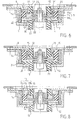
- Figure 6 highlights, on an axial section of a hydropneumatic variant of the modular set of elastic connection according to the invention, the presence of stops limit switch in elastomeric composition.
- the variant represents a structure similar to that of Figure 1, composed of an armature assembly upper annular (AS) and an armature assembly lower annular (AI), the filling fluid of the upper (11) and lower (12) annular chambers being made up of liquid and gas.
- AS armature assembly upper annular
- AI armature assembly lower annular
- the connecting elements lower elastic (13), intermediate (14) and upper (15) each include an end of travel stop, in elastomeric composition, respectively (30), (31) and (32).
- the role of said end of travel stops (30, 31, 32), is to intervene, as a contact for limiting race, in order to curb deflections during efforts significant rebounds or shocks.
- Said end of travel stops (30, 31, 32) are therefore integral parts of elastic connection elements lower (13), intermediate (14) and upper (15) respectively.
- the end stop (30) of the element lower elastic connection (13) is arranged on its face forming the bottom of the annular chamber lower (12) and located opposite the tongue sealing (22).
- the end stop upper intermediate (31) is located on the face of the intermediate elastic connection element (14) forming the bottom of the upper half-chamber (11a) of the upper annular chamber (11) and opposite the upper sealing tab (25), like the stopper limit switch (32) is located on the face of the upper elastic connection (15) forming the wall upper of the lower half-chamber (11b) of the chamber upper annular (11) and opposite the tongue sealing (23).
- the stroke limitation contact operates between the end stop (30) and the face lower of the internal connection frame (4) or either between the lower intermediate limit stop (32) and the upper face of the internal connection frame (4) either between the upper end stop (31) and the face lower of the upper frame (9).
- FIG. 7 shows, also in axial section, a another variant of the modular link assembly elastic, pneumatic version, with two chambers reduced volume annulars and limit stops in elastomeric composition.
- the structure of the device is similar to that of the Figure 1 and has the same constituents forming a upper ring armature assembly (AS) and a lower annular reinforcement (AI) assembly; the closed volume is significantly reduced compared to that of previously described variants, the elements of lower elastic connection (13) and intermediate (14) being much larger.
- AS upper ring armature assembly
- AI annular reinforcement
- the end stop (30) carried by the lower elastic connection element (13) is made up of a notable thickness of elastomeric composition.
- the walls of the lower annular chamber (12) are here constituted partially from the underside of the reinforcement internal connection (4) and of the lower face of the element intermediate elastic connection (14), in part high, the other three walls being formed of elements in elastomeric composition, namely the tongue lower sealing (24) of the connecting frame internal (4), the limit stop (30) and the tongue sealing (22) carried by the connecting element lower elastic (13).
- the filling fluid of the closed volume is here constituted of a gas, the flexible elastic connection assembly operating by pneumatic effect associated with the effect elastic produced by the deformation of the elements of elastic connection (13, 14, 15) constituting the assembly of connection in elastomeric composition (RE).
- the limitation relative movements take place by limiting contact stroke, in the lower annular chamber (12), between the limit stop (30) and the underside of the internal connecting frame (4) or, in the chamber upper annular (11), either between the end stop of high stroke (31) and the internal face of the armature upper (9), either between the limit stop (32) and the upper face of the internal connecting frame (4).
- FIG. 8 illustrates, also in axial section, a variant of the flexible elastic connection assembly in which the device has two annular chambers non-communicating filled with fluid consisting of a viscous material in the presence of gas, forming a whole modular hydropneumatic.
- the closed volume is distributed between an upper annular chamber (11) enclosed in the upper ring reinforcement assembly (AS) and a lower annular chamber (12) enclosed in the lower annular reinforcement assembly (AI).
- the lower elastic connection elements (13), intermediate (14) and upper (15) which form the assembly of connection in elastomeric composition (RE) can have end stops of the type shown in Figures 6 and 7 or be deprived of it, as represented.
- the filling fluid of the closed volume is, in this variant, consisting of a viscous material in the presence of a gas. Modulation of static and dynamic rigidities is done by the choice of the proportion of the constituents, but an additional damping effect is obtained by the viscosity of the viscous material and is therefore flexible according to said viscosity. It is obvious that the brewing viscous material in the passage (11c) which connects the half upper chamber (11a) to the lower half chamber (11b) of the upper annular chamber (11) and causes a shearing of said viscous material resulting in a drop in dynamic stiffness in the frequencies growing is directly influenced by viscosity of said viscous material as by the geometric definition of the passage (11c).
- Figure 9 shows, also in axial section, the connection of the annular chambers (11, 12) constituting closed volume to a fluid management system filling in a hydroelastic assembly or modular hydropneumatic elastic connection according to the invention.
- the device has a structure similar to that of the Figure 1 but is also equipped with connecting channels (33, 34) for modulating the composition of the filling the closed volume.
- the annular chambers upper (11) and lower (12) are, most often, both connected to the fluid management system of filling, as shown, but it is quite obvious that only one of the annular chambers could have a such connection.
- the lower connecting channel (33) replaces the shutter (27) of the previous versions to set communication, through the filling orifice (26) passing through the lower frame (7), the annular chamber lower (12) with the fluid management system filling, such as the upper connecting channel (34) replaces the shutter (29) to connect the upper annular chamber (11) with the same system of filling fluid management through the orifice (28) passing through the upper frame (9).
- the annular chambers (11, 12) or the connecting channels (33, 34) are provided with sealing means (not shown), such as non-return valves or devices ensuring a similar function, guaranteeing the tightness of said annular chambers (11, 12).
- Control of the fluid for filling the closed volume has the advantage of allowing the adaptation of stiffness initial and saturation of the modular set of elastic connection, for example, to the rolling profile meet.
- the modular connection assembly elastic can become an "active" device, the filling fluid management becoming a set of direct steering managed by requests from either of the shock absorber or of another body participating in the movement to cushion.
- lower elastic connection elements (13), intermediate (14) and upper (15) can include or be end stops devoid, as illustrated.
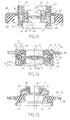
- Figure 10 shows the axial section of an assembly hydropneumatic elastic connection including reinforcements have a particular shape.
- the upper ring reinforcement assembly (AS) is, in this variant, formed of an upper frame (9), an internal upper linkage frame (4 ') and a external upper linkage frame (8 ').
- the upper frame (9) has a double U shape inverted, the internal barrel (35) of which is connected to the periphery (36) via an annular zone (37).
- the two upper connecting frames (4 ', 8') are intimately linked to the elastic connection element upper (15) by their internal faces.
- the walls of the upper annular chamber (11) are then formed by the annular zone (37) and the part upper of the internal shaft (35) and the periphery (36) of the upper frame (9) for the upper part and the sides and by the upper face of the element upper elastic connection (15), for the part low.
- the upper annular chamber (11) does not have upper and lower half-chambers, but a single cavity. There is therefore no shearing of the liquid by mixing between two half-chambers and, by consequently, no reduction in dynamic stiffness.
- the internal upper link fittings (4 ') and external (8 ') are clamped between the internal faces of the periphery (36) and internal barrel (35) of the frame upper (9) for mounting the device.
- the lower ring reinforcement assembly element (AI) consists of an internal lower frame (3), a lower intermediate frame (4 ") and one frame outer (7), S-shaped, the upper shaft (38) is embedded in the elastomeric composition constituting the upper elastic connection element (15).
- the walls of the lower annular chamber (12) are formed by the part of the connecting element upper elastic (15) between the upper barrel (38) of the outer frame (7) and the connecting frame internal upper re (4 '), part of the extension horizontal (39) of said upper shaft (38) and an element of lower elastic connection (13), intimately linked to the internal face of the internal lower frame (3) and to a rigid reinforcement (40) interposed between the reinforcement of lower link (4 ") and said connecting element lower elastic (13).
- an element of external elastic connection (41) also made of elastomeric composition and intended for elastic recovery charges.
- Load transfer is thus decoupled by compared to the fixing on the shock absorber rod, only difference in the behavior of the modular set of elastic connection compared to the previous variants.
- the device illustrated comprises a filling fluid composed of a liquid and a gas, but it is quite obvious for those skilled in the art that, according to the needs of the application, the filling fluid can be only a gas, then leading to a modular set of elastic connection with pneumatic effect or only a liquid of appropriate viscosity leading to a version hydroelastic of the device.
- Figure 11 illustrates another particular arrangement of the flexible elastic connection assembly, in which an external filling element is included, elastomeric composition, figure on which have been omitted the means of connection to the structure to be absorbed.
- the device comprises, like the previous variants, a enclosed volume consisting of an upper annular chamber (11) and a lower annular chamber (12), here shown containing a filling fluid comprising a liquid in the presence of a gas.
- the walls of the upper annular chamber (11), at single cavity, are formed by the underside of the upper elastic connection element (15) and by the shoulder (41) of the internal upper frame (5) for the upper part, by the sealing tongue (23) and by the vertical extension (42) of the shoulder (41) of the frame internal upper (5), for the sides, and by the face upper of the elastic connection element intermediate (14) and the upper face of the external link (8), for the lower part.
- the upper elastic connection element (15) is intimately linked, by its lateral faces, on the one hand to the internal upper reinforcement (5) and on the other hand to a peripheral upper frame (43).
- the element of intermediate connection (14) is itself intimately linked to an internal connection frame (4 ') and to the frame of external link (8). It further comprises two stops for upper (31) and lower (44) upper limit switches, all two in elastomeric composition.
- the walls of the lower annular chamber (12) are, here, formed, for the upper part, by the face bottom of the external connection frame (8), for sides, on the one hand by the sealing tongue (30) carried by the lower elastic connection element (13) and on the other hand by the internal vertical barrel (45) of the internal lower frame (3), and for the lower part, by the upper face of the connection element lower elastic (13) and by the horizontal extension (46) of said internal vertical barrel (45).
- the lower elastic connection element (13) is intimately linked, by its lateral faces, on the one hand to the leg (47) of the internal lower frame (3) and, on the other part to an external lower frame (48).
- the device thus constituted further comprises a filling element (50), in elastomeric composition, intended for load recovery. He is united with the elastic connection device by fixing means (51) allowing the assembly of the peripheral reinforcement lower (49) to which the element of filling (50), both on the upper reinforcement and lower external (43, 48) and on the connecting frame external (8).
- Figure 12 shows another variant of the assembly modular elastic connection, in version hydropneumatic, in which the filling fluid contains a high proportion of liquid.
- the closed volume of this device consists of two annular chambers (11, 12) each comprising two half-chambers, high (11a) and low (11b) for the bedroom upper annular (11) and two internal half-chambers (12i) and external (12e) for the lower annular chamber (12).
- connection element intermediate elastic in which the barrel is embedded bent (52) of the internal connecting frame (4) as well as the vertical barrel (53) of the external connection frame (8), and which has two end stops, high (31) and low (44).
- the underside of the element of upper elastic connection (15) and the upper face of the intermediate elastic connection element (14) delimit, with the internal faces of the frame upper internal (5), upper armature (9), the upper face of the external connection frame (8) and the upper face of the horizontal barrel (54) of the armature of internal connection (4), the upper annular chamber (11).
- connection between the annular reinforcement assemblies lower (AI) and upper (AS) is performed by through a part of the end (4i) of the internal connection frame (4) sandwiched between the face lower of the horizontal end (5h) of the armature internal upper (5) and the upper face of the end horizontal (3h) of the internal lower frame (3) and, on the other hand, from the end (8e) of the connecting frame external (8) clamped between the underside of the horizontal end (9h) of the upper frame (9) and the upper face of the horizontal end (7h) of the lower frame (7).
- the composition of the filling the closed volume is different from a room annular to each other.
- the upper annular chamber (11) it consists of approximately 90% of liquid and 10% of gas, while in the lower annular chamber (12), the proportion of liquid is approximately 80%. This difference allows, in operation, an adjustment asymmetric behavior of the modular set of elastic connection.
- Figure 13 depicts a simplified variant of the assembly modular elastic connection, in version hydropneumatic, in which the enclosed volume is consisting of a single annular chamber.
- the existence of a single annular chamber (55) reduces the number of components, the set of connection in elastomeric composition (RE) being consisting only of elastic connection elements upper (15) and lower (13), mounted respectively between the external face of the vertical barrel (5v) of the frame lower internal (5) and the upper face of the frame upper (9) on the one hand and between the internal faces of the vertical barrel (3v) of the internal lower frame (3), an upper peripheral frame (56), provided bores (57) to allow assembly, and the internal frame (7).
- the device also includes a additional elastic connection element (58).
- the single annular chamber (55) contains a filling here consisting of approximately 70% liquid and 30% gas.
- the illustrated variant has a single annular chamber (55) placed in the upper part of the device and, by therefore more effective in upward movements of the shock absorber rod, therefore in shock stress, but it is obvious to those skilled in the art that if damping of rebound loads was to be privileged, the device would be designed so that the single annular chamber (55) is located in the lower part of the device.
- the manufacturing method of the present invention consists of molding by conventional industry means rubber processing, after pre-treatment reinforcements for their adhesion to the elements of elastic connection constituting the element of connection in elastomeric composition (RE).
- the different reinforcements receive a treatment of degreasing and coating with a primary coat bonding followed by a layer of adhering agent.
- Reinforcements and elastomeric compositions constitutive of the elastic connection elements are then arranged in the imprint of a form mold which is then closed and placed under a press.
- the device is removed from the mold and then goes to the filling phase of the closed volume, any finishing operations that can complete these steps.
- the flexible elastic connection element is then ready to be delivered to the automaker for assembly on vehicle.
- the element flexible elastic connection according to the present invention the advantage of allowing the modulation of the characteristics by a partially independent modulation of the static rigidity, rigidity and dynamic gain, modulation of the damping effect, a limitation of travel without mechanical contact, a possibility of controlling the composition of the filling, control which can be carried out directly by the stresses of the shock absorber leading, therefore, to an active elastic connection system.
- the interest of the present invention lies in the its effects are made without contact of elements mechanics such as those of conventional systems, which are often causing noise pollution due to phenomena of friction and mechanical docking.
- the device according to the invention also has the advantage of being insensitive to conical grips induced by the damper rod, and keeps, in this case, the same effort-deflection law, which is not the case conventional devices.
Landscapes
- Engineering & Computer Science (AREA)
- General Engineering & Computer Science (AREA)
- Mechanical Engineering (AREA)
- Combined Devices Of Dampers And Springs (AREA)
- Vehicle Body Suspensions (AREA)
Description
- la figure 1 est une-vue, en coupe axiale, d'un ensemble modulable de liaison élastique selon l'invention, comportant un volume clos constitué de deux chambres annulaires non communicantes ;
- la figure 2 est la vue de dessus de la même variante ;
- la figure 3 est une coupe partielle de l'ensemble modulable de liaison élastique, en version pneumatique, c'est-à-dire dont le fluide de remplissage du volume clos est constitué d'un gaz et illustre le comportement en déflexion du dispositif ;
- la figure 4 est une demi-coupe d'une autre variante de l'ensemble modulable de liaison élastique, à deux chambres annulaires non communicantes, dans la version constituant un ensemble hydropneumatique modulable de liaison élastique, c'est-à-dire dont le fluide de remplissage du volume clos est constitué d'un liquide ou d'un matériau visqueux en présence d'un gaz ; elle illustre le comportement en déflexion du dispositif ;
- la figure 5 illustre, sur un diagramme, la variation des déflexions en fonction des efforts appliqués, pour un ensemble modulable de suspension élastique de type hydropneumatique, comparativement à celle des dispositifs de l'art antérieur ;
- la figure 6 met en évidence, sur une vue en coupe axiale d'une variante hydropneumatique de l'ensemble modulable de liaison élastique, la présence de butées de fin de course en composition élastomérique ;
- la figure 7 représente, en coupe axiale également, une autre variante de l'ensemble modulable de liaison élastique, en version pneumatique, comportant deux chambres annulaires non communicantes, de volume clos réduit, et des butées de fin de course en composition élastomérique ;
- la figure 8 illustre, aussi en coupe axiale, une variante de l'ensemble modulable de liaison élastique, dans laquelle le dispositif présente deux chambres annulaires non communicantes remplies de fluide constitué d'un liquide visqueux en présence de gaz, formant un ensemble hydropneumatique modulable ;
- la figure 9 montre, en coupe axiale également, le raccordement des chambres annulaires constituant le volume clos à un système de gestion du fluide de remplissage dans un ensemble hydroélastique ou hydropneumatique modulable de liaison élastique ;
- la figure 10 est la coupe axiale d'un ensemble hydropneumatique de liaison élastique dont les armatures présentent une forme particulière ;
- la figure 11 illustre une autre disposition spécifique de l'ensemble modulable de liaison élastique dans laquelle est inclus un élément de remplissage extérieur, en composition élastomérique ;
- la figure 12 propose une variante de l'ensemble modulable de liaison élastique, en version hydropneumatique ;
- la figure 13 décrit une variante simplifiée de l'ensemble modulable de liaison élastique, en version-hydropneumatique, dans laquelle le volume clos est constitué d'une chambre annulaire unique.
- au voisinage de l'origine, les zones (A) correspondent à des déflexions de faible amplitude engendrées par une route peu accidentée présentant un revêtement de bonne qualité ;
- les zones (A') sont des zones transitoires, correspondant à des déflexions de moyenne amplitude, engendrées par les conditions de conduite habituelles ;
- les zones (A") correspondent à des déflexions importantes, positives ou négatives, provoquées par le franchissement d'obstacles, engendrant chocs et rebonds.
| Rigidité statique en fonction de la composition du fluide de remplissage du volume clos | |||
| Remplissage du volume clos | Rigidité statique daN/mm | Limitation des débattements mm à 1000 daN | |
| % gaz | % liquide | ||
| 100 | 0 | 50 | aucune |
| 60 | 40 | 58 | aucune |
| 40 | 60 | 60 | ± 10 |
| 25 | 75 | 70 | ± 8,5 |
| 10 | 90 | 80 | ± 6,5 |
| 0 | 100 | 340 | ± 3,5 |
| Rigidité dynamique en fonction de la fréquence pour différentes compositions du fluide de remplissage | |||||
| Fréquence Hertz | Nature du remplissage | ||||
| Témoin 100 % gaz chambres ouvertes Kt (N/mm) | Ensemble modulable de liaison élastique | ||||
| 10 % gaz 90 % liquide | 100 % liquide | ||||
| Kd1 | variation Kd1/Kt | Kd2 | variation Kd2/Kt | ||
| 2 | 650 | 1050 | 1,6 | 3660 | 5,6 |
| 20 | 682 | 1145 | 1,7 | 3827 | 5,6 |
| 50 | 701 | 1155 | 1,6 | 3914 | 5,6 |
| 100 | 725 | 1040 | 1,4 | 3990 | 5,5 |
| 150 | 755 | 850 | 1,1 | 4010 | 5,3 |
| 200 | 800 | 800 | 1,0 | 4100 | 5,1 |
Claims (13)
- Méthode de modulation d'un ensemble modulable de liaison élastique interposé, pour filtrer les vibrations, entre la tige (6) d'un amortisseur (1) de véhicule et une structure (2) à amortir, ledit ensemble comprenant au moins deux armatures annulaires rigides dont l'une (3-5) est solidarisée avec la tige (6) et l'autre (7-9) avec la structure (2), lesdites armatures étant liées l'une à l'autre par au moins deux éléments annulaires élastomériques (13-15), qui délimitent entre eux un espace clos (11, 12, 55) contenant un fluide, le volume dudit espace clos étant modifié par la déformation sous contrainte desdits éléments annulaires élastomériques, l'espace clos étant totalement étanche par rapport à son environnement externe et ledit fluide comportant une phase gazeuse et au moins une phase liquide, caractérisée par le fait que la modulation des rigidités statique Ks et dynamique Kd dudit ensemble est obtenue par variation du rapport des volumes occupés par la phase gazeuse et la phase liquide, afin de régler une suspension plus ou moins ferme en comportement et de limiter les débattements de la tige (6) de l'amortisseur (1) pour les efforts importants, sans engendrer un surcroít de nuisance acoustique.
- Méthode selon la revendication 1, caractérisée par le fait que l'espace clos est constitué par une chambre (55) annulaire unique, l'ensemble ne comprenant que deux éléments (13, 15) annulaires élastomériques.
- Méthode selon la revendication 1, caractérisée par le fait que l'ensemble comprend trois éléments annulaires élastomériques et que l'espace clos est constitué par deux chambres (11, 12) annulaires non communiquantes, à savoir une chambre (11) annulaire supérieure, délimitée par un élément (15) annulaire élastomérique supérieur et par un élément (14) annulaire élastomérique intermédiaire, filtrant les vibrations dues aux chocs et une chambre (12) annulaire inférieure, délimitée par ledit élément (14) annulaire élastomérique intermédiaire et par un élément (13) annulaire élastomérique inférieur, filtrant les vibrations dues aux rebonds.
- Méthode selon l'une des revendications 1 à 3, caractérisée par le fait que la phase liquide contenue dans l'espace clos comprend au moins deux composants de viscosités différentes.
- Méthode selon l'une des revendications 1 à 4, caractérisée par le fait que la phase liquide contenue dans l'espace clos comprend au moins un matériau visqueux.
- Méthode selon la revendication 3, caractérisée par le fait qu'au moins un des éléments annulaires élastomériques inférieur (13), intermédiaire (14) et supérieur (15) comprend au moins une butée de fin de course (30, 31, 31, 44) en composition élastomérique.
- Méthode selon l'une des revendications 3 ou 6, caractérisée par le fait que le volume clos est relié à un système de gestion du fluide utilisé pour le remplissage dudit espace clos, afin de pouvoir moduler les rigidités statique et dynamique en fonction du profil routier par l'intermédiaire d'au moins un canal de liaison (33, 34) débouchant dans au moins une des chambres annulaires (11, 12) par un orifice de remplissage (26, 28) ménagé dans au moins une des armatures.
- Méthode selon la revendication 7, caractérisée par le fait que le système de gestion du fluide utilisé pour le remplissage de l'espace clos est constitué par un distributeur à plusieurs positions.
- Méthode selon la revendication 7, caractérisée par le fait que le système de gestion du fluide est constitué d'un dispositif de pilotage direct par les sollicitations générées par un mécanisme participant aux mouvements à amortir, ce qui constitue un ensemble modulable de liaison élastique actif.
- Méthode selon la revendication 1, caractérisée par le fait qu'une des armatures annulaires rigides est liée à l'autre armature par trois éléments annulaires élastomériques espacés, lesdites armatures et les éléments annulaires élastomériques définissant deux chambres (11, 12) annulaires fermées étanches l'une par rapport à l'autre.
- Méthode selon la revendication 10, caractérisée par le fait que l'une (11) desdites chambres annulaires est subdivisée en deux chambres (11a, 11b) annulaires plus petites, qui ne communiquent l'une avec l'autre que par un espace (11c) annulaire étroit.
- Méthode selon la revendication 11, caractérisée par le fait que la chambre, qui est subdivisée en deux chambres plus petites, contient une phase liquide visqueuse, ladite phase liquide étant soumise au cisaillement lorsqu'elle passe à travers ledit espace (11c) annulaire étroit.
- Méthode selon l'une des revendications précédentes, caractérisée par le fait que les éléments élastomériques annulaires (13-15) sont aptes à se déformer sous l'effet de sollicitations importantes transmises par la phase liquide incompressible du fluide de remplissage, cette déformation se traduisant par un bombement des faces des éléments élastomériques annulaires opposées au fluide comprimé, lequel bombement sert de butée de fin de course pouvant venir en contact avec une partie d'armature de la structure (2) et ainsi limiter les déformations.
Priority Applications (6)
| Application Number | Priority Date | Filing Date | Title |
|---|---|---|---|
| FR9307358A FR2706558B1 (fr) | 1993-06-16 | 1993-06-16 | Ensemble modulaire de liaison élastique formant attache d'amortisseur et bloc filtrant. |
| AT94402956T ATE199135T1 (de) | 1994-12-20 | 1994-12-20 | Methode zur modulation einer elastischen modularen befestigungs- und filtereinheit zur stossdämpferbefestigung |
| DE1994626700 DE69426700T2 (de) | 1994-12-20 | 1994-12-20 | Methode zur Modulation einer elastischen modularen Befestigungs- und Filtereinheit zur Stossdämpferbefestigung |
| EP94402956A EP0718130B1 (fr) | 1993-06-16 | 1994-12-20 | Méthode de modulation d'un ensemble modulaire de liaison élastique formant attache d'amortisseur et bloc filtrant |
| JP7000123A JPH08184346A (ja) | 1993-06-16 | 1995-01-05 | 調整可能な弾性結合アセンブリ |
| US08/408,083 US5595374A (en) | 1993-06-16 | 1995-03-23 | Variable elastic coupling assembly forming shock absorber attachment and filtering block |
Applications Claiming Priority (4)
| Application Number | Priority Date | Filing Date | Title |
|---|---|---|---|
| FR9307358A FR2706558B1 (fr) | 1993-06-16 | 1993-06-16 | Ensemble modulaire de liaison élastique formant attache d'amortisseur et bloc filtrant. |
| EP94402956A EP0718130B1 (fr) | 1993-06-16 | 1994-12-20 | Méthode de modulation d'un ensemble modulaire de liaison élastique formant attache d'amortisseur et bloc filtrant |
| JP7000123A JPH08184346A (ja) | 1993-06-16 | 1995-01-05 | 調整可能な弾性結合アセンブリ |
| US08/408,083 US5595374A (en) | 1993-06-16 | 1995-03-23 | Variable elastic coupling assembly forming shock absorber attachment and filtering block |
Publications (2)
| Publication Number | Publication Date |
|---|---|
| EP0718130A1 EP0718130A1 (fr) | 1996-06-26 |
| EP0718130B1 true EP0718130B1 (fr) | 2001-02-14 |
Family
ID=27442936
Family Applications (1)
| Application Number | Title | Priority Date | Filing Date |
|---|---|---|---|
| EP94402956A Expired - Lifetime EP0718130B1 (fr) | 1993-06-16 | 1994-12-20 | Méthode de modulation d'un ensemble modulaire de liaison élastique formant attache d'amortisseur et bloc filtrant |
Country Status (4)
| Country | Link |
|---|---|
| US (1) | US5595374A (fr) |
| EP (1) | EP0718130B1 (fr) |
| JP (1) | JPH08184346A (fr) |
| FR (1) | FR2706558B1 (fr) |
Families Citing this family (16)
| Publication number | Priority date | Publication date | Assignee | Title |
|---|---|---|---|---|
| FR2706558B1 (fr) * | 1993-06-16 | 1995-08-25 | Caoutchouc Manuf Plastique | Ensemble modulaire de liaison élastique formant attache d'amortisseur et bloc filtrant. |
| DE19639556A1 (de) * | 1996-09-26 | 1998-04-09 | Mannesmann Boge Gmbh | Vorrichtung zur Tilgung von Schwingungen |
| KR100488786B1 (ko) * | 2002-05-15 | 2005-05-12 | 기아자동차주식회사 | 유압식 스트럿 마운팅 구조 |
| US20070001358A1 (en) * | 2005-06-29 | 2007-01-04 | Freudenberg-Nok General Partnership | Tunable top mount |
| DE102005054205B4 (de) * | 2005-11-14 | 2008-03-27 | Woco Avs Gmbh | Federbein für einen Schwingungsdämpfer eines Kraftfahrzeugs |
| DE102006028879A1 (de) * | 2006-06-21 | 2007-12-27 | Zf Friedrichshafen Ag | Pralldämpfer |
| US20090020929A1 (en) * | 2007-07-18 | 2009-01-22 | Freudenberg-Nok General Partnership | Strut Top Mount With Axial Hydraulic Element |
| US8439336B2 (en) * | 2010-09-01 | 2013-05-14 | GM Global Technology Operations LLC | Dual path hydraulic strut mounts and vehicular suspension systems including the same |
| KR101410649B1 (ko) * | 2012-12-05 | 2014-06-24 | 현대자동차주식회사 | 차량용 동흡진기 |
| US9133903B2 (en) * | 2013-03-15 | 2015-09-15 | The Pullman Company | Hydroelastic fluids for fluid filled elastomeric damping devices |
| US8960696B2 (en) | 2013-04-16 | 2015-02-24 | Zhongli North America Inc. | Strut top mount with MCU and integral travel limiter |
| US10132409B2 (en) | 2016-02-24 | 2018-11-20 | Honda Motor Co., Ltd. | Damper seal |
| US9969230B2 (en) * | 2016-04-11 | 2018-05-15 | Beijingwest Industries Co., Ltd. | Top mount assembly having adjustable damping characteristics |
| KR102750673B1 (ko) * | 2020-03-23 | 2025-01-06 | 현대자동차주식회사 | 차량 현가장치용 인슐레이터 및 그 제조 방법 |
| NO346317B1 (en) * | 2020-12-03 | 2022-06-07 | Momentum Tech As | Viscoelastic damper assembly |
| US12338871B2 (en) * | 2021-06-02 | 2025-06-24 | Vibracoustic Usa, Inc. | Hydraulic mount assembly and method |
Family Cites Families (24)
| Publication number | Priority date | Publication date | Assignee | Title |
|---|---|---|---|---|
| US3403899A (en) * | 1966-04-29 | 1968-10-01 | Gen Motors Corp | Viscous damped bushing |
| FR2357790A1 (fr) * | 1976-04-27 | 1978-02-03 | Boge Gmbh | Support de moteur, elastique, a amortissement hydraulique, notamment pour vehicule a moteur |
| JPS5881240A (ja) * | 1981-11-10 | 1983-05-16 | Mazda Motor Corp | 弾性体ブツシユ |
| JPS60179543A (ja) * | 1984-02-28 | 1985-09-13 | Nissan Motor Co Ltd | パワ−ユニツトのマウンテイング装置 |
| DE3501260A1 (de) * | 1984-05-28 | 1986-07-17 | Continental Gummi-Werke Ag, 3000 Hannover | Hydraulisch gedaempftes elastisches lager |
| FR2572338B1 (fr) * | 1984-10-30 | 1988-12-09 | Ouest Cie | Attache elastique d'amortisseur |
| JPS61125905A (ja) * | 1984-11-22 | 1986-06-13 | Toyota Motor Corp | 車両のサスペンシヨン |
| JPS61125906A (ja) * | 1984-11-26 | 1986-06-13 | Toyota Motor Corp | 車両のサスペンシヨン |
| JPS61129309A (ja) * | 1984-11-27 | 1986-06-17 | Toyota Motor Corp | 車両のサスペンシヨン |
| JPS6256641A (ja) * | 1985-09-03 | 1987-03-12 | Kayaba Ind Co Ltd | 周波数感応ブツシユ |
| JPS62215142A (ja) * | 1985-12-10 | 1987-09-21 | Bridgestone Corp | 防振装置 |
| GB8608259D0 (en) * | 1986-04-04 | 1986-05-08 | Dunlop Ltd | Anti-vibration mountings |
| JPS62270844A (ja) * | 1987-02-26 | 1987-11-25 | Honda Motor Co Ltd | 流体入りマウント |
| JPS63255110A (ja) * | 1987-04-10 | 1988-10-21 | Showa Mfg Co Ltd | 油圧緩衝器用マウントラバ−のバネ定数可変機構 |
| JPH0238729A (ja) * | 1988-07-29 | 1990-02-08 | Bridgestone Corp | 防振装置 |
| JPH02117450U (fr) * | 1989-03-09 | 1990-09-20 | ||
| JPH0747976B2 (ja) * | 1989-04-14 | 1995-05-24 | 東海ゴム工業株式会社 | サスペンション用アッパサポート |
| JPH03249441A (ja) * | 1990-02-28 | 1991-11-07 | Tokai Rubber Ind Ltd | 流体入り筒型マウント装置 |
| JPH03288034A (ja) * | 1990-03-30 | 1991-12-18 | Tokai Rubber Ind Ltd | 高粘性流体封入式マウント装置 |
| FR2671839A1 (fr) * | 1991-01-17 | 1992-07-24 | Hutchinson | Perfectionnements aux supports antivibratoires hydrauliques. |
| JPH04300710A (ja) * | 1991-03-29 | 1992-10-23 | Nissan Motor Co Ltd | ストラットアッパマウント装置 |
| JPH04302728A (ja) * | 1991-03-29 | 1992-10-26 | Toyoda Gosei Co Ltd | 液封入防振装置 |
| US5180144A (en) * | 1991-09-03 | 1993-01-19 | General Motors Corporation | Air spring module for a damper |
| FR2706558B1 (fr) * | 1993-06-16 | 1995-08-25 | Caoutchouc Manuf Plastique | Ensemble modulaire de liaison élastique formant attache d'amortisseur et bloc filtrant. |
-
1993
- 1993-06-16 FR FR9307358A patent/FR2706558B1/fr not_active Expired - Fee Related
-
1994
- 1994-12-20 EP EP94402956A patent/EP0718130B1/fr not_active Expired - Lifetime
-
1995
- 1995-01-05 JP JP7000123A patent/JPH08184346A/ja active Pending
- 1995-03-23 US US08/408,083 patent/US5595374A/en not_active Expired - Lifetime
Also Published As
| Publication number | Publication date |
|---|---|
| FR2706558A1 (fr) | 1994-12-23 |
| JPH08184346A (ja) | 1996-07-16 |
| EP0718130A1 (fr) | 1996-06-26 |
| US5595374A (en) | 1997-01-21 |
| FR2706558B1 (fr) | 1995-08-25 |
Similar Documents
| Publication | Publication Date | Title |
|---|---|---|
| FR2706558A1 (fr) | Ensemble modulaire de liaison élastique formant attache d'amortisseur et bloc filtrant. | |
| EP1436524B1 (fr) | Articulation hydroelastique rotulee | |
| US4700934A (en) | Pretensionable and hydraulically damped mounting element | |
| EP0490724A1 (fr) | Attache hydroélastique de suspension et biélette de liaison élastique liée à cette attache | |
| FR2735833A1 (fr) | Dispositif d'amortissement a remplissage de fluide ayant une grande rigidite elastique dans deux directions mutuellement perpendiculaires | |
| EP0735294B1 (fr) | Articulation élastique notamment pour un train roulant de véhicule automobile | |
| EP0359655B1 (fr) | Perfectionnements apportés aux manchons antivibratoires hydrauliques | |
| EP0286527A1 (fr) | Support élastique à amortissement hydraulique intégré avec cloison rigide à circuit de liquide ajustable | |
| FR2695446A1 (fr) | Ensemble amortisseur de vibrations à double tube. | |
| EP1217249A1 (fr) | Manchon antivibratoire et véhicule automobile comportant un tel manchon | |
| FR2914717A1 (fr) | Palier hydraulique a amortissement biaxial | |
| FR2812363A1 (fr) | Manchon antivibratoire hydraulique | |
| EP0277056A1 (fr) | Dispositif élastique d'isolation antivibratoire à amortissement hydraulique intégré et butées de limitation de débattements internes | |
| EP0511054B1 (fr) | Perfectionnements aux manchons antivibratoires hydrauliques | |
| FR2713731A1 (fr) | Perfectionnement aux supports antivibratoires hydrauliques et à leurs procédés de fabrication. | |
| FR2622268A1 (fr) | Ressort a douille en caoutchouc | |
| FR2495718A1 (fr) | Support amortisseur, notamment pour moteur a combustion interne de vehicule automobile | |
| FR3092376A1 (fr) | Butee hydraulique de suspension de vehicule automobile a masse inertielle | |
| FR2899154A1 (fr) | Dispositif de butee de suspension de vehicule | |
| FR2702812A1 (fr) | Ensemble de soupape d'obturation pour un amortisseur, d'un montage simplifié. | |
| FR2655113A1 (fr) | Dispositif d'amortissement en elastomere rempli d'un fluide. | |
| FR2828253A1 (fr) | Palier a air | |
| FR2900211A1 (fr) | Palier elastomere a amortissement hydraulique | |
| FR2671839A1 (fr) | Perfectionnements aux supports antivibratoires hydrauliques. | |
| FR2828135A1 (fr) | Palier de jambe de suspension |
Legal Events
| Date | Code | Title | Description |
|---|---|---|---|
| PUAI | Public reference made under article 153(3) epc to a published international application that has entered the european phase |
Free format text: ORIGINAL CODE: 0009012 |
|
| AK | Designated contracting states |
Kind code of ref document: A1 Designated state(s): AT BE CH DE DK ES GB GR IE IT LI LU MC NL PT SE |
|
| 17P | Request for examination filed |
Effective date: 19960730 |
|
| RIN1 | Information on inventor provided before grant (corrected) |
Inventor name: DE FONTENAY, ETIENNE Inventor name: CHARETTE, CHRISTIAN |
|
| 17Q | First examination report despatched |
Effective date: 19961114 |
|
| GRAG | Despatch of communication of intention to grant |
Free format text: ORIGINAL CODE: EPIDOS AGRA |
|
| RTI1 | Title (correction) |
Free format text: METHOD FOR MODULATING A MODULAR ASSEMBLY FOR ELASTIC CONNECTION FORMING SHOCK ABSORBER MOUNT AND FILTERING BLOC |
|
| GRAG | Despatch of communication of intention to grant |
Free format text: ORIGINAL CODE: EPIDOS AGRA |
|
| GRAH | Despatch of communication of intention to grant a patent |
Free format text: ORIGINAL CODE: EPIDOS IGRA |
|
| GRAH | Despatch of communication of intention to grant a patent |
Free format text: ORIGINAL CODE: EPIDOS IGRA |
|
| GRAA | (expected) grant |
Free format text: ORIGINAL CODE: 0009210 |
|
| RAP1 | Party data changed (applicant data changed or rights of an application transferred) |
Owner name: MICHELIN AVS |
|
| AK | Designated contracting states |
Kind code of ref document: B1 Designated state(s): AT BE CH DE DK ES GB GR IE IT LI LU MC NL PT SE |
|
| PG25 | Lapsed in a contracting state [announced via postgrant information from national office to epo] |
Ref country code: SE Free format text: LAPSE BECAUSE OF FAILURE TO SUBMIT A TRANSLATION OF THE DESCRIPTION OR TO PAY THE FEE WITHIN THE PRESCRIBED TIME-LIMIT Effective date: 20010214 Ref country code: NL Free format text: LAPSE BECAUSE OF FAILURE TO SUBMIT A TRANSLATION OF THE DESCRIPTION OR TO PAY THE FEE WITHIN THE PRESCRIBED TIME-LIMIT Effective date: 20010214 Ref country code: IT Free format text: LAPSE BECAUSE OF FAILURE TO SUBMIT A TRANSLATION OF THE DESCRIPTION OR TO PAY THE FEE WITHIN THE PRE;WARNING: LAPSES OF ITALIAN PATENTS WITH EFFECTIVE DATE BEFORE 2007 MAY HAVE OCCURRED AT ANY TIME BEFORE 2007. THE CORRECT EFFECTIVE DATE MAY BE DIFFERENT FROM THE ONE RECORDED.SCRIBED TIME-LIMIT Effective date: 20010214 Ref country code: IE Free format text: LAPSE BECAUSE OF FAILURE TO SUBMIT A TRANSLATION OF THE DESCRIPTION OR TO PAY THE FEE WITHIN THE PRESCRIBED TIME-LIMIT Effective date: 20010214 Ref country code: GR Free format text: LAPSE BECAUSE OF NON-PAYMENT OF DUE FEES Effective date: 20010214 Ref country code: ES Free format text: THE PATENT HAS BEEN ANNULLED BY A DECISION OF A NATIONAL AUTHORITY Effective date: 20010214 Ref country code: AT Free format text: LAPSE BECAUSE OF FAILURE TO SUBMIT A TRANSLATION OF THE DESCRIPTION OR TO PAY THE FEE WITHIN THE PRESCRIBED TIME-LIMIT Effective date: 20010214 |
|
| REF | Corresponds to: |
Ref document number: 199135 Country of ref document: AT Date of ref document: 20010215 Kind code of ref document: T |
|
| REG | Reference to a national code |
Ref country code: CH Ref legal event code: EP |
|
| REG | Reference to a national code |
Ref country code: IE Ref legal event code: FG4D Free format text: FRENCH |
|
| REF | Corresponds to: |
Ref document number: 69426700 Country of ref document: DE Date of ref document: 20010322 |
|
| GBT | Gb: translation of ep patent filed (gb section 77(6)(a)/1977) |
Effective date: 20010301 |
|
| PG25 | Lapsed in a contracting state [announced via postgrant information from national office to epo] |
Ref country code: PT Free format text: LAPSE BECAUSE OF FAILURE TO SUBMIT A TRANSLATION OF THE DESCRIPTION OR TO PAY THE FEE WITHIN THE PRESCRIBED TIME-LIMIT Effective date: 20010514 Ref country code: DK Free format text: LAPSE BECAUSE OF FAILURE TO SUBMIT A TRANSLATION OF THE DESCRIPTION OR TO PAY THE FEE WITHIN THE PRESCRIBED TIME-LIMIT Effective date: 20010514 |
|
| NLV1 | Nl: lapsed or annulled due to failure to fulfill the requirements of art. 29p and 29m of the patents act | ||
| REG | Reference to a national code |
Ref country code: IE Ref legal event code: FD4D |
|
| PG25 | Lapsed in a contracting state [announced via postgrant information from national office to epo] |
Ref country code: MC Free format text: LAPSE BECAUSE OF NON-PAYMENT OF DUE FEES Effective date: 20011220 Ref country code: LU Free format text: LAPSE BECAUSE OF NON-PAYMENT OF DUE FEES Effective date: 20011220 |
|
| PLBE | No opposition filed within time limit |
Free format text: ORIGINAL CODE: 0009261 |
|
| STAA | Information on the status of an ep patent application or granted ep patent |
Free format text: STATUS: NO OPPOSITION FILED WITHIN TIME LIMIT |
|
| PG25 | Lapsed in a contracting state [announced via postgrant information from national office to epo] |
Ref country code: LI Free format text: LAPSE BECAUSE OF NON-PAYMENT OF DUE FEES Effective date: 20011231 Ref country code: CH Free format text: LAPSE BECAUSE OF NON-PAYMENT OF DUE FEES Effective date: 20011231 Ref country code: BE Free format text: LAPSE BECAUSE OF NON-PAYMENT OF DUE FEES Effective date: 20011231 |
|
| REG | Reference to a national code |
Ref country code: GB Ref legal event code: IF02 |
|
| 26N | No opposition filed | ||
| BERE | Be: lapsed |
Owner name: MICHELIN AVS Effective date: 20011231 |
|
| REG | Reference to a national code |
Ref country code: CH Ref legal event code: PL |
|
| PGFP | Annual fee paid to national office [announced via postgrant information from national office to epo] |
Ref country code: DE Payment date: 20081219 Year of fee payment: 15 |
|
| PGFP | Annual fee paid to national office [announced via postgrant information from national office to epo] |
Ref country code: GB Payment date: 20081216 Year of fee payment: 15 |
|
| GBPC | Gb: european patent ceased through non-payment of renewal fee |
Effective date: 20091220 |
|
| PG25 | Lapsed in a contracting state [announced via postgrant information from national office to epo] |
Ref country code: DE Free format text: LAPSE BECAUSE OF NON-PAYMENT OF DUE FEES Effective date: 20100701 |
|
| PG25 | Lapsed in a contracting state [announced via postgrant information from national office to epo] |
Ref country code: GB Free format text: LAPSE BECAUSE OF NON-PAYMENT OF DUE FEES Effective date: 20091220 |