EP0716422B1 - Boiling water nuclear reactor fuel assembly divided into four sub-assemblies and comprising a channel - Google Patents
Boiling water nuclear reactor fuel assembly divided into four sub-assemblies and comprising a channel Download PDFInfo
- Publication number
- EP0716422B1 EP0716422B1 EP95307863A EP95307863A EP0716422B1 EP 0716422 B1 EP0716422 B1 EP 0716422B1 EP 95307863 A EP95307863 A EP 95307863A EP 95307863 A EP95307863 A EP 95307863A EP 0716422 B1 EP0716422 B1 EP 0716422B1
- Authority
- EP
- European Patent Office
- Prior art keywords
- sub
- fuel bundle
- fuel
- channel
- bundle
- Prior art date
- Legal status (The legal status is an assumption and is not a legal conclusion. Google has not performed a legal analysis and makes no representation as to the accuracy of the status listed.)
- Expired - Lifetime
Links
Images


Classifications
-
- G—PHYSICS
- G21—NUCLEAR PHYSICS; NUCLEAR ENGINEERING
- G21C—NUCLEAR REACTORS
- G21C3/00—Reactor fuel elements and their assemblies; Selection of substances for use as reactor fuel elements
- G21C3/30—Assemblies of a number of fuel elements in the form of a rigid unit
- G21C3/32—Bundles of parallel pin-, rod-, or tube-shaped fuel elements
- G21C3/324—Coats or envelopes for the bundles
-
- G—PHYSICS
- G21—NUCLEAR PHYSICS; NUCLEAR ENGINEERING
- G21C—NUCLEAR REACTORS
- G21C3/00—Reactor fuel elements and their assemblies; Selection of substances for use as reactor fuel elements
- G21C3/30—Assemblies of a number of fuel elements in the form of a rigid unit
- G21C3/32—Bundles of parallel pin-, rod-, or tube-shaped fuel elements
- G21C3/322—Means to influence the coolant flow through or around the bundles
-
- G—PHYSICS
- G21—NUCLEAR PHYSICS; NUCLEAR ENGINEERING
- G21C—NUCLEAR REACTORS
- G21C5/00—Moderator or core structure; Selection of materials for use as moderator
- G21C5/02—Details
-
- Y—GENERAL TAGGING OF NEW TECHNOLOGICAL DEVELOPMENTS; GENERAL TAGGING OF CROSS-SECTIONAL TECHNOLOGIES SPANNING OVER SEVERAL SECTIONS OF THE IPC; TECHNICAL SUBJECTS COVERED BY FORMER USPC CROSS-REFERENCE ART COLLECTIONS [XRACs] AND DIGESTS
- Y02—TECHNOLOGIES OR APPLICATIONS FOR MITIGATION OR ADAPTATION AGAINST CLIMATE CHANGE
- Y02E—REDUCTION OF GREENHOUSE GAS [GHG] EMISSIONS, RELATED TO ENERGY GENERATION, TRANSMISSION OR DISTRIBUTION
- Y02E30/00—Energy generation of nuclear origin
- Y02E30/30—Nuclear fission reactors
Definitions
- This invention relates to the fuel bundles for boiling water nuclear reactors, and more particularly to an improved and enlarged fuel bundle channel design.
- a Boiling Water Reactor generates steam in its core.
- This core is composed of an array of side-by-side, vertically upstanding square sectioned fuel bundles. These fuel bundles divide the core region of the reactor into the so-called core bypass region exterior of the fuel bundles, and the core region interior of the fuel bundles.
- the flow region interior of the fuel bundles is at a higher pressure than the bypass region.
- water is forced to circulate through the fuel bundles by pumping.
- the flow region exterior of the fuel bundles contains non-boiling water and is used to provide increased presence of water for the moderation of high speed neutrons to low speed neutrons so that the chain reaction in the boiling water reactor can continue.
- a fuel bundle consists of a group of fuel rods between an upper tie- plate and lower tie-plate.
- the upper tie-plate and the lower tie-plate and the fuel rods extending therebetween are provided with a polygon section, which section is preferably square. This section is surrounded by a water impervious channel which forms a water tight boundary from the lower tie-plate to the upper tie-plate.
- the fuel channels perform three distinct and separate functions.
- the channels form individual coolant cells in which the fuel rods or fuel assemblies are located, thus separating boiling coolant from moderator coolant within the core region.
- adjacent channel sides form the control rod blade guiding annulus.
- the channels position and laterally support the fuel assemblies.
- BWR fuel assembly size has remained basically the same for approximately three decades.
- a typical size is 140.16 by 140.16 mm square (5.518 by 5.518 inches square) by 4.239 m (166.9 inches) long.
- bundle size was determined by the capability of the reactivity control system to keep the core in a state of cold shut-down with sufficient reactivity margin, considering one control rod projecting out of the core. This size was appropriate considering the known D-lattice, C-lattice and N-lattice designs in which one cruciform control blade is inserted between every four bundles in the core. More recent advances in the use of burnable poisons and axial enrichment variation have made it possible to increase the fuel assembly size beyond the typical BWR size.
- the bundle size can be increased even more from the viewpoint of reactivity control.
- This arrangement is called the K-lattice core.
- the bundle width for this application is approximately 161.9 mm (6.375 inches) or slightly bigger than the bundle width for other lattices as noted above.
- a BWR having a first assembly generally in accordance with the preamble of claim 1 hereof is described in DE-A-3427372 (equivalent to US-A-4,632,804). Fuel assemblies with increased numbers of fuel rods are described in JP-A-04296693.
- the present invention provides a boiling water nuclear reactor which includes a plurality of fuel bundle assemblies as claimed in claim 1 hereof.
- a large fuel channel design which consists of a large channel with inner channels or cross ties which divide the large channel into four quadrants. Each quadrant serves as a cell for a sub-fuel bundle. Each sub-fuel bundle is similar in size to a traditional BWR fuel bundle.
- each channel and inter-bundle fuel support serves as a "basket" for the four sub-fuel bundles.
- the water cross type bundle approach includes a large channel divided by inner channel parts or cross ties which divide the channel into four discrete quadrants. These inner channel parts or cross ties provide or define a cruciform passage centrally located vis-a-vis the channel (isolated from the sub-fuel bundles), and through which coolant is adapted to flow.
- One feature of this water cross type bundle is that water gaps that are maintained on all four sides of each sub-bundle similar to existing BWR lattice configurations in the core.
- the water cross separates the sub-fuel bundles from each other, axially along the entire length of the channel.
- the spacing between adjacent large bundles within the core is the same as the spacing between the sub-bundles of each large bundle, as defined by the water cross. It is this arrangement that provides substantially equal cooling flow along all four sides of each sub-fuel bundle.
- the arrangement of CRD's between the various large bundles is such that opposite corners of each large bundle are bracketed by a pair of CRD blades or wings.
- inlet nozzles are provided (one for each sub-bundle) in the inter-bundle support plate, simplified with coolant via a common inlet opening.
- This embodiment has the ability to orifice each sub-bundle separately in order to assure good thermal-hydraulic-nuclear stability.
- a fuel bundle assembly for a boiling water nuclear reactor comprising an open ended tubular channel subdivided into four quadrants by four interior partitions, each quadrant having a sub-fuel bundle assembly comprising a plurality of fuel rods extending between upper and lower tie plates; an inter-bundle support plate receiving a lower end of the channel and having four flow openings at an upper end thereof, the lower tie plate of the sub-fuel bundle supported in a respective on of the openings.
- the channel design described herein reduces the time required for fuel handling by allowing roughly four times more fuel to be moved per lift compared to current BWR fuel channel designs.
- the large channel design has an increased load carrying capability under seismic events, and is structurally more resistant to channel bow and bulge deformation. It will also be appreciated that the new large channel design in accordance with this invention supports the three distinct and separate functions of conventional channels, discussed hereinabove.
- Boiling Water Reactor (BWR) core 10 including a cruciform Control Rod Drive (CRD) 12 projecting upwardly through a core plate P.
- the CRD 12 is centrally located relative to four fuel rod bundle assemblies, only one of which is shown at 14 in Figure 1, but see also Figure 2.
- the assembly 14 includes a large, open-ended tubular channel 16 provided with inner channels or cross ties 18, 20, 22 and 24 which divide the channel 16 into four corresponding quadrants A, B, C and D.
- the large channel 16 is substantially square in section, but with rounded corners.
- Each quadrant serves as a cell for a sub-fuel bundle 26 of otherwise conventional BWR bundle construction, except as noted below.
- each sub-fuel bundle comprises an 8 X 8 array of fuel rods.
- the present invention utilizes a single large channel 16 to embrace as many as four sub-fuel bundles 26.
- the substantially square channel 16 may have side dimensions about twice that of the conventional channel.
- the inner cross ties 18, 20, 22 and 24 are'arranged to provide a cruciform moderator passage (or water cross) 28 between the sub-fuel bundles 26, and specifically between the cross ties 18, 20, 22 and 24, with moderator introduced into the passage 28 via ports 30 located in the inter-bundle fuel support described below.
- Each cruciform passage 28 is provided with a plurality of reinforcements 29 in each section of the passage, and arranged at vertically spaced intervals along the length of the channel. The reinforcements 29 and cross ties 18, 20, 22 and 24 serve to reinforce the channel 16 and thus resist undesirable channel bowing or bulging.
- each sub-fuel bundle is cooled by in-channel flow on two sides and out-of-channel flow on the remaining two sides.
- each sub-fuel bundle 26 comprises a plurality of fuel rods 46 supported at their lower ends by a fuel rod supporting grid 48 of a lower tie plate assembly 50.
- the fuel rods 46 are secured at their upper ends by an upper tie plate 51 (see Figures 1 and 2).
- the lower inlet nozzle portion 52 of each lower tie plate 50 is circular in shape, and is seated within a corresponding opening 54 in the inter-bundle support plate 40.
- each plate 40 is provided with four such openings 54 to accommodate the lower tie plates of the four sub-fuel bundles supported on each plate 40.
- Plate 40 is otherwise of generally square shape and of a cross sectional size similar to the large channel 16.
- the four openings 54 in plate 40 each taper downwardly and inwardly along surfaces 56 such that the vertical centerlines of the openings 54 are offset relative to the vertical centerline of a common inlet opening 62, such that coolant flow is caused to change direction as it flows upwardly through the plate 40 into the individual sub-fuel bundles 26.
- a common inlet opening 62 as defined by the mounting sleeve portion 65 of the plate 40 supplies liquid coolant to the four openings 54.
- This sleeve portion 64 is formed exteriorly with a tapered annular seating surface at 66 and a horizontally oriented seating flange 68 which engages complementary surfaces 70, 72, respectively, on the support cup 42, fixed to the core plate P and seated within the plate P in a similar manner.
- the openings 54 of the support plate 40 are surrounded by tapered seating surfaces 74 and a horizontal top surface 76 upon which mating surfaces 78, 80, respectively, of the lower tie plates 50 are seated.
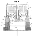
- the large channel 16 is received over the upper edge 82 of peripheral side wall 84 of the support plate 40, as best seen in Figure 4.
- the top of the support plate is also formed with a cruciform groove or slot 86 which receives the inner channels or cross ties 18, 20, 22 and 24 and through which coolant is supplied via ports 30 ( Figure 2).
- the entire sub-fuel bundle assembly 14 including channel 16 and four sub-fuel bundle assemblies 26 can be lifted from the support cup 44 (as shown in Figure 5) during refuel or repair procedures.
Landscapes
- Physics & Mathematics (AREA)
- Engineering & Computer Science (AREA)
- Plasma & Fusion (AREA)
- General Engineering & Computer Science (AREA)
- High Energy & Nuclear Physics (AREA)
- Fuel Cell (AREA)
Applications Claiming Priority (2)
| Application Number | Priority Date | Filing Date | Title |
|---|---|---|---|
| US08/348,155 US5519746A (en) | 1994-11-28 | 1994-11-28 | Large BWR fuel channel design |
| US348155 | 1994-11-28 |
Publications (2)
| Publication Number | Publication Date |
|---|---|
| EP0716422A1 EP0716422A1 (en) | 1996-06-12 |
| EP0716422B1 true EP0716422B1 (en) | 2001-10-04 |
Family
ID=23366855
Family Applications (1)
| Application Number | Title | Priority Date | Filing Date |
|---|---|---|---|
| EP95307863A Expired - Lifetime EP0716422B1 (en) | 1994-11-28 | 1995-11-03 | Boiling water nuclear reactor fuel assembly divided into four sub-assemblies and comprising a channel |
Country Status (4)
| Country | Link |
|---|---|
| US (1) | US5519746A (ja) |
| EP (1) | EP0716422B1 (ja) |
| JP (1) | JPH08254589A (ja) |
| DE (1) | DE69523021T2 (ja) |
Cited By (1)
| Publication number | Priority date | Publication date | Assignee | Title |
|---|---|---|---|---|
| TWI460738B (zh) * | 2006-12-22 | 2014-11-11 | Global Nuclear Fuel Americas | 燃料支架及用以調整核子反應器內之冷卻流的方法 |
Families Citing this family (15)
| Publication number | Priority date | Publication date | Assignee | Title |
|---|---|---|---|---|
| US6097779A (en) * | 1998-02-17 | 2000-08-01 | General Electric Company | Fuel bundle and control rod assembly for a nuclear reactor |
| JP3788045B2 (ja) | 1998-07-01 | 2006-06-21 | 株式会社日立製作所 | 燃料集合体 |
| EP1168370B1 (en) * | 2000-06-20 | 2007-02-21 | General Electric Company | Core configuration for a nuclear reactor |
| US6813327B1 (en) * | 2000-10-19 | 2004-11-02 | General Electric Company | Core support for an F-lattice core of a boiling water nuclear reactor |
| US7424412B2 (en) * | 2002-12-23 | 2008-09-09 | Global Nuclear Fuel - Americas, Llc | Method of determining nuclear reactor core design with reduced control blade density |
| US20050069079A1 (en) * | 2003-09-12 | 2005-03-31 | Boardman Charles Edward | Modular reactor containment system |
| US7463711B1 (en) | 2004-05-25 | 2008-12-09 | Areva Np Inc. | Fuel channel fastener |
| KR101515116B1 (ko) | 2007-12-26 | 2015-04-24 | 토륨 파워 인코포레이티드 | 원자로(대용물), 원자로(대용물)를 위한 드라이버-브리딩 모듈들로 구성된 연료 집합체 및 연료 집합체용 연료 요소 |
| US8116423B2 (en) | 2007-12-26 | 2012-02-14 | Thorium Power, Inc. | Nuclear reactor (alternatives), fuel assembly of seed-blanket subassemblies for nuclear reactor (alternatives), and fuel element for fuel assembly |
| US9355747B2 (en) | 2008-12-25 | 2016-05-31 | Thorium Power, Inc. | Light-water reactor fuel assembly (alternatives), a light-water reactor, and a fuel element of fuel assembly |
| ES2429118T3 (es) * | 2009-09-30 | 2013-11-13 | Areva Np | Módulo para formar conjuntos de combustible nuclear y conjuntos de combustible nuclear formados de una pluralidad de dichos módulos |
| US10192644B2 (en) | 2010-05-11 | 2019-01-29 | Lightbridge Corporation | Fuel assembly |
| WO2011143172A1 (en) | 2010-05-11 | 2011-11-17 | Thorium Power, Inc. | Fuel assembly with metal fuel alloy kernel and method of manufacturing thereof |
| US10170207B2 (en) | 2013-05-10 | 2019-01-01 | Thorium Power, Inc. | Fuel assembly |
| US9287012B2 (en) | 2010-07-25 | 2016-03-15 | Global Nuclear Fuel—Americas, LLC | Optimized fuel assembly channels and methods of creating the same |
Family Cites Families (24)
| Publication number | Priority date | Publication date | Assignee | Title |
|---|---|---|---|---|
| US3929565A (en) * | 1971-02-03 | 1975-12-30 | Asea Atom Ab | Nuclear reactor with groups of elongated absorber units carried by control rods |
| JPS51140090A (en) * | 1975-05-30 | 1976-12-02 | Hitachi Ltd | Fuel aggregate |
| SE420545B (sv) * | 1979-07-03 | 1981-10-12 | Asea Atom Ab | Brenslepatron for en kokarreaktor |
| SE424237B (sv) * | 1980-10-29 | 1982-07-05 | Asea Atom Ab | Brensleelement for en kokarreaktor |
| SE423760B (sv) * | 1980-11-05 | 1982-05-24 | Asea Atom Ab | Kernbrenslepatron |
| SE424931B (sv) * | 1980-12-19 | 1982-08-16 | Asea Atom Ab | Brenslepatron med vattenfordelningsrenna |
| SE433986B (sv) * | 1982-07-12 | 1984-06-25 | Asea Atom Ab | Kernbrenslepatron |
| SE437738B (sv) * | 1983-08-04 | 1985-03-11 | Asea Atom Ab | Brenslepatron for en kokvattenreaktor |
| SE445500B (sv) * | 1984-11-12 | 1986-06-23 | Asea Atom Ab | Brenslepatron |
| US4659543A (en) * | 1984-11-16 | 1987-04-21 | Westinghouse Electric Corp. | Cross brace for stiffening a water cross in a fuel assembly |
| SE450177B (sv) * | 1985-10-16 | 1987-06-09 | Asea Atom Ab | Kernbrenslepatron |
| US4753774A (en) * | 1986-02-06 | 1988-06-28 | Westinghouse Electric Corp. | Orificing of water cross inlet in BWR fuel assembly |
| SE454822B (sv) * | 1986-04-29 | 1988-05-30 | Asea Atom Ab | Kernbrenslepatron till en kernreaktor |
| US4740350A (en) * | 1986-07-22 | 1988-04-26 | Westinghouse Electric Corp. | BWR fuel assembly having fuel rod spacers axially positioned by exterior springs |
| US4759912A (en) * | 1986-12-09 | 1988-07-26 | Westinghouse Electric Corp. | BWR fuel assembly having hybrid fuel design |
| EP0307705A1 (de) * | 1987-09-10 | 1989-03-22 | Siemens Aktiengesellschaft | Kernreaktor-Brennelement |
| SE464995B (sv) * | 1989-11-14 | 1991-07-08 | Asea Atom Ab | Braenslepatron foer en kokarreaktor |
| SE464993B (sv) * | 1989-11-14 | 1991-07-08 | Asea Atom Ab | Braenslepatron foer en kokarreaktor |
| SE464994B (sv) * | 1989-11-14 | 1991-07-08 | Asea Atom Ab | Braenslepatron foer en kokarreaktor |
| JPH04296693A (ja) * | 1991-03-26 | 1992-10-21 | Toshiba Corp | 原子炉の炉心 |
| JPH04299283A (ja) * | 1991-03-28 | 1992-10-22 | Toshiba Corp | 原子炉の燃料集合体 |
| DE4117622A1 (de) * | 1991-05-29 | 1992-12-03 | Siemens Ag | Kerngitterstruktur fuer kernreaktoren, insbesondere fuer heizreaktoren |
| JP3055820B2 (ja) * | 1991-07-05 | 2000-06-26 | 株式会社東芝 | 燃料集合体と炉心 |
| SE509238C2 (sv) * | 1993-07-05 | 1998-12-21 | Asea Atom Ab | Reaktorhärd |
-
1994
- 1994-11-28 US US08/348,155 patent/US5519746A/en not_active Expired - Fee Related
-
1995
- 1995-11-03 DE DE69523021T patent/DE69523021T2/de not_active Expired - Fee Related
- 1995-11-03 EP EP95307863A patent/EP0716422B1/en not_active Expired - Lifetime
- 1995-11-24 JP JP7305294A patent/JPH08254589A/ja active Pending
Cited By (1)
| Publication number | Priority date | Publication date | Assignee | Title |
|---|---|---|---|---|
| TWI460738B (zh) * | 2006-12-22 | 2014-11-11 | Global Nuclear Fuel Americas | 燃料支架及用以調整核子反應器內之冷卻流的方法 |
Also Published As
| Publication number | Publication date |
|---|---|
| US5519746A (en) | 1996-05-21 |
| DE69523021T2 (de) | 2002-06-06 |
| JPH08254589A (ja) | 1996-10-01 |
| EP0716422A1 (en) | 1996-06-12 |
| DE69523021D1 (de) | 2001-11-08 |
Similar Documents
| Publication | Publication Date | Title |
|---|---|---|
| EP0716422B1 (en) | Boiling water nuclear reactor fuel assembly divided into four sub-assemblies and comprising a channel | |
| EP0146896B1 (en) | A partial grid for a nuclear reactor fuel assembly | |
| US7672418B2 (en) | Control rod guide tube and method for providing coolant to a nuclear reactor fuel assembly | |
| US20220076853A1 (en) | Optimized nuclear fuel core design for a small modular reactor | |
| JP2503026B2 (ja) | 燃料集合体用のフロ―ミキシング中間格子 | |
| US4844861A (en) | Fuel assembly for nuclear reactors | |
| US6934350B1 (en) | Core configuration for a nuclear reactor | |
| EP0260601B1 (en) | Fuel rod spacer with means for diverting liquid coolant flow | |
| EP0751527B1 (en) | BWR fuel assembly having fuel rods with variable fuel rod pitches | |
| US4970048A (en) | Mixing grid with fins for nuclear fuel assembly | |
| EP0692793B1 (en) | Nuclear reactor fuel assembly comprising lower tie plate debris catcher | |
| EP1202289B1 (en) | Core support for an F-lattice core of a boiling water nuclear reactor | |
| US4738819A (en) | Boiling water nuclear reactor fuel assembly with cross-flow elimination at upper spacer locations | |
| US5859886A (en) | Fuel assembly for a boiling water reactor | |
| EP0200111B1 (en) | Improved boiling water nuclear reactor fuel assembly | |
| US5598450A (en) | Fuel bundle with adjustable flow and reactivity | |
| EP0514215B1 (en) | Part length rod placement in boiling water reactor fuel assembly for reactivity control | |
| JPH0627277A (ja) | 沸騰水型原子炉の作動方法 | |
| EP0709856A1 (en) | Nuclear reactor fuel assembly comprising a plate type debris catcher | |
| EP1168370B1 (en) | Core configuration for a nuclear reactor | |
| JPH04296693A (ja) | 原子炉の炉心 | |
| JPH0452913B2 (ja) | ||
| JPH0570797B2 (ja) | ||
| JPH01199191A (ja) | 原子炉 | |
| JPS6276488A (ja) | 原子炉用燃料集合体 |
Legal Events
| Date | Code | Title | Description |
|---|---|---|---|
| PUAI | Public reference made under article 153(3) epc to a published international application that has entered the european phase |
Free format text: ORIGINAL CODE: 0009012 |
|
| AK | Designated contracting states |
Kind code of ref document: A1 Designated state(s): CH DE IT LI NL SE |
|
| 17P | Request for examination filed |
Effective date: 19961212 |
|
| 17Q | First examination report despatched |
Effective date: 19970909 |
|
| GRAG | Despatch of communication of intention to grant |
Free format text: ORIGINAL CODE: EPIDOS AGRA |
|
| GRAG | Despatch of communication of intention to grant |
Free format text: ORIGINAL CODE: EPIDOS AGRA |
|
| GRAH | Despatch of communication of intention to grant a patent |
Free format text: ORIGINAL CODE: EPIDOS IGRA |
|
| GRAH | Despatch of communication of intention to grant a patent |
Free format text: ORIGINAL CODE: EPIDOS IGRA |
|
| GRAA | (expected) grant |
Free format text: ORIGINAL CODE: 0009210 |
|
| AK | Designated contracting states |
Kind code of ref document: B1 Designated state(s): CH DE IT LI NL SE |
|
| REG | Reference to a national code |
Ref country code: CH Ref legal event code: NV Representative=s name: RITSCHER & SEIFERT Ref country code: CH Ref legal event code: EP |
|
| REF | Corresponds to: |
Ref document number: 69523021 Country of ref document: DE Date of ref document: 20011108 |
|
| PLBE | No opposition filed within time limit |
Free format text: ORIGINAL CODE: 0009261 |
|
| STAA | Information on the status of an ep patent application or granted ep patent |
Free format text: STATUS: NO OPPOSITION FILED WITHIN TIME LIMIT |
|
| 26N | No opposition filed | ||
| PGFP | Annual fee paid to national office [announced via postgrant information from national office to epo] |
Ref country code: SE Payment date: 20021018 Year of fee payment: 8 |
|
| PGFP | Annual fee paid to national office [announced via postgrant information from national office to epo] |
Ref country code: NL Payment date: 20021021 Year of fee payment: 8 Ref country code: CH Payment date: 20021021 Year of fee payment: 8 |
|
| PG25 | Lapsed in a contracting state [announced via postgrant information from national office to epo] |
Ref country code: SE Free format text: LAPSE BECAUSE OF NON-PAYMENT OF DUE FEES Effective date: 20031104 |
|
| PG25 | Lapsed in a contracting state [announced via postgrant information from national office to epo] |
Ref country code: LI Free format text: LAPSE BECAUSE OF NON-PAYMENT OF DUE FEES Effective date: 20031130 Ref country code: CH Free format text: LAPSE BECAUSE OF NON-PAYMENT OF DUE FEES Effective date: 20031130 |
|
| PG25 | Lapsed in a contracting state [announced via postgrant information from national office to epo] |
Ref country code: NL Free format text: LAPSE BECAUSE OF NON-PAYMENT OF DUE FEES Effective date: 20040601 |
|
| EUG | Se: european patent has lapsed | ||
| REG | Reference to a national code |
Ref country code: CH Ref legal event code: PL |
|
| NLV4 | Nl: lapsed or anulled due to non-payment of the annual fee |
Effective date: 20040601 |
|
| PG25 | Lapsed in a contracting state [announced via postgrant information from national office to epo] |
Ref country code: IT Free format text: LAPSE BECAUSE OF NON-PAYMENT OF DUE FEES;WARNING: LAPSES OF ITALIAN PATENTS WITH EFFECTIVE DATE BEFORE 2007 MAY HAVE OCCURRED AT ANY TIME BEFORE 2007. THE CORRECT EFFECTIVE DATE MAY BE DIFFERENT FROM THE ONE RECORDED. Effective date: 20051103 |
|
| PGFP | Annual fee paid to national office [announced via postgrant information from national office to epo] |
Ref country code: DE Payment date: 20071221 Year of fee payment: 13 |
|
| PG25 | Lapsed in a contracting state [announced via postgrant information from national office to epo] |
Ref country code: DE Free format text: LAPSE BECAUSE OF NON-PAYMENT OF DUE FEES Effective date: 20090603 |