EP0715689B1 - Hydraulischer gasverdichter - Google Patents
Hydraulischer gasverdichter Download PDFInfo
- Publication number
- EP0715689B1 EP0715689B1 EP94924224A EP94924224A EP0715689B1 EP 0715689 B1 EP0715689 B1 EP 0715689B1 EP 94924224 A EP94924224 A EP 94924224A EP 94924224 A EP94924224 A EP 94924224A EP 0715689 B1 EP0715689 B1 EP 0715689B1
- Authority
- EP
- European Patent Office
- Prior art keywords
- piston
- gas
- pressure
- chamber
- housing
- Prior art date
- Legal status (The legal status is an assumption and is not a legal conclusion. Google has not performed a legal analysis and makes no representation as to the accuracy of the status listed.)
- Expired - Lifetime
Links
Images


Classifications
-
- F—MECHANICAL ENGINEERING; LIGHTING; HEATING; WEAPONS; BLASTING
- F04—POSITIVE - DISPLACEMENT MACHINES FOR LIQUIDS; PUMPS FOR LIQUIDS OR ELASTIC FLUIDS
- F04B—POSITIVE-DISPLACEMENT MACHINES FOR LIQUIDS; PUMPS
- F04B25/00—Multi-stage pumps
- F04B25/02—Multi-stage pumps of stepped piston type
Definitions
- the invention relates to a device for compressing gas according to the features of the preamble of claim 1.
- Devices in this regard are available on the market in a large number of designs and embodiments. A distinction is essentially made between two designs, namely motor-driven or hydraulically / pneumatically driven compressors.
- the known gas compressors which are also referred to as compressors, have a large structure and a complicated construction, so that the manufacturing and maintenance costs are high due to the high assembly and maintenance costs involved.
- a known device for compressing gas according to EP 0 193 498 A2
- the known gas compressor With the known gas compressor, a two-stage compression process always takes place alternately on both sides of the device.
- the separating element of the known device is formed by two housing ends, between which the middle piston is arranged to be movable and the gas introduced at low pressure alternately ejects into the compression chamber for the higher pressure. Due to the only two-stage compression process, however, very high pressures cannot be achieved.
- a generic gas compressor is known with a stepped piston movable by means of a drive, which enables a four-stage compression process.
- a moving hydraulic working cylinder which has a working piston that divides the hydraulic cylinder into two fluid chambers of variable volume, is used as a separating element, along which the piston is movably guided in the housing are.
- the movable housing part of the separating element designed as a hydraulic cylinder is firmly connected to the latter, which surrounds the separating element with a cylindrical, closed outer surface while maintaining a distance. Because of this configuration, the known gas compressor has a large structure, in particular in the transverse direction, and due to the variety of parts, which are also subject to wear due to the movable components, the functional reliability is impaired and increased maintenance is required.
- the invention has for its object to provide a device for compressing gas, which is extremely small and with which high compression values can still be achieved and functionally reliable with little installation and maintenance is in operation.
- a corresponding object is achieved by a device having the features of claim 1.
- the two fluid chambers for the piston drive are limited by the piston and the separating element for a three-stage compression cycle and the separating element is arranged stationary in the device, an increase in pressure of the gas with an extremely small-sized device is possible from very small to very high values further possible, for example from 5 bar to 400 bar.
- the gas compressor according to the invention is also provided with components which are not very movable and which can be subject to wear, which in addition to reliable operation entails low production and maintenance costs.
- the stationary or stationary separating element which could also be seen as the so-called “stator” of the device, thus allows the fluid to be supplied directly through its interior, so that the movement of the piston, which could also be referred to as a flying piston, takes place along the outer circumference of the separating element , is in no way disabled.
- Pressure oil is preferably used as the fluid; however, a pneumatic drive for special compressor applications could also take the place of the fluid drive.
- the separation chambers each have at least one inlet and one outlet valve for the series connection, the respective inlet valve of a separation chamber following in the row being connected via a connecting line to the outlet valve of the preceding separation chamber assigned to it.
- the three-stage compression process can be realized with only six valves, which benefits the operational safety of the device.
- the inlet and outlet valves are preferably formed from check valves working in opposite directions and are used in pairs for a compressor stage, whereby so-called “Bernoulli valves” can preferably be used, as described in the Applicant's German Utility Model G 94 08 660.5. It has been shown that these dynamically reversing check valves are almost insensitive to reactions from high pressure lines, so that trouble-free operation of the compressor is guaranteed. With the "Bernoulli valves" mentioned, on the one hand, the harmful spaces can be kept to a minimum and on the other hand no external devices for controlling the valves are required, for example in the form of a camshaft.
- the interior of the piston can be connected to the surroundings via a pressure relief duct, a relief space preferably kept at ambient pressure being delimited by the separating element in the piston and in the housing. Because of this pressure relief towards the atmosphere, the oil and gas sides are reliably separated from one another in the device according to the invention. Any leaking oil that escapes can be returned directly to the tank, the gas pressure that is present increasing due to the pressure relief.
- the movable piston has an anti-rotation device which is provided with a pointer device which indicates the position of the piston and which, in order to switch the direction of movement of the piston in its two dead center positions, interacts with a switching device with limit switches.
- a pointer device which indicates the position of the piston and which, in order to switch the direction of movement of the piston in its two dead center positions, interacts with a switching device with limit switches.
- the piston area of the piston acting in the respective separation chamber is made smaller than the piston area in the previous pressure stage.
- the area ratios of the separation or pressure chambers mentioned also determine the maximum achievable final pressure of the compressor, with the selected graduated area ratios simply stopping when a predeterminable maximum final pressure value is reached, so that an overload by pressure and Influence of temperature is avoided with certainty.
- At least some of the connecting lines are connected to these heat exchangers.
- the device according to the invention is in via the pressure relief channel Inside the piston and / or in the relief chamber, a coolant can be supplied. As a result, the heat occurring in the area of the piston during the compression process can be dissipated better.
- the gas discharge can be infinitely predetermined by controlling the fluid quantities that can be fed into the fluid chambers, preferably by means of a pump and / or a throttle.
- the gas discharge from the compressor can therefore be regulated continuously, independently of the pressure conditions, by regulating the fluid delivery rate, setting the supply rate of the pump, and additionally or alternatively using a regulating throttle.
- Another possibility is a demand-controlled extension of the switchover time at the two dead center positions of the piston, so that a high degree of efficiency can be guaranteed even with a low throughput.
- the device according to the invention is preferably used for an internal gas pressure system in which the gas quantities compressed to high pressure are stored in a memory from which the gas quantities necessary for an injection molding process for the mold can be called up. It has been shown that internal gas pressure systems can be operated more economically with the device according to the invention than with the previously known compressors. By retrieving the highly compressed gas quantities required for an injection molding process from the storage, smooth operation of injection molding machines of any kind is possible.
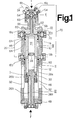
- the device according to the invention shown in FIG. 1 has a housing, designated as a whole by 10, but consisting of several parts.
- a separating element 12 is present in the lower half of the device and arranged inside the housing 10.
- a piston 14 is movably guided along the separating element 12, which passes through two dead center positions for a three-stage compression cycle and which, for receiving the gas to be compressed, preferably in the form of nitrogen gas, with the housing 10 has three separating chambers III, IV and V connected in series limited, which form the compression chambers of the compressor.
- the separation chambers III, IV and V have three inlet valves 16a, b, c and three outlet valves 18a, b, c.
- the pair of valves 16a, 18a is part of the first suction or pressure stage, whereas the pair of valves 16b, 18b are part of the second suction or pressure stage and the pair of valves 16c, 18c are part of the third suction or pressure stage of the compressor.
- the respective inlet valve 16b, 16c of a separation chamber IV, V following in the row is connected to the outlet valve 18a or 18b via a connecting line 20, which is only shown schematically in FIG previous separation chamber III or IV connected.
- the separating element 12 For driving the piston 14, the separating element 12 has two separate feeds 26a, b for the fluid in the form of hydraulic oil, each of which ends at one end 28a, b in a fluid or oil chamber I, II of variable volume, which separated from each other by means of a seal 30 and which are delimited by the piston 14 and the separating element 12.
- the Sealing 30 is formed by a separating bead arranged on the separating element 12, along the outer circumference of which a sealing ring runs in the usual and therefore not described in detail.
- a relief chamber VI arranged in the region of the underside of the compressor is delimited by the separating element 12, the piston 14 and the housing 10.
- This relief chamber VI is kept at ambient pressure by, as is shown in particular in FIG. 7, it is connected to the environment via three lateral recesses 32 which are laterally delimited by four longitudinal webs 34 of the housing 10.
- shell-like housing segments 36 are placed over the recesses 32 and are firmly connected to the longitudinal webs 34, the cover produced in this way is not pressure-tight, with the result that the ambient pressure in the relief chamber VI is established.
- Another relief chamber VII is formed by the interior of the piston 14, which is connected to the environment via a pressure relief duct 38, so that the ambient pressure also arises in the relief chamber VII.
- the pressure relief channel 38 mentioned can also be divided into two channel sections 38a, b at its end pointing towards the environment.
- the movable piston 14 has an anti-rotation device, designated 40, which is provided with a pointer device 42 which indicates the position of the piston 14 and which switches the direction of movement of the piston 14 in its two dead center positions interacts with a switching device (not shown) with two end position switches 44 opposite one another in the direction of travel of the piston 14.
- a pointer device 42 which indicates the position of the piston 14 and which switches the direction of movement of the piston 14 in its two dead center positions interacts with a switching device (not shown) with two end position switches 44 opposite one another in the direction of travel of the piston 14.
- the individual chambers I to VII of the compressor are each separated from one another by customary and therefore not described sliding seals.
- the piston 14 is jammed or to avoid tipping, as the only part of the device which is moved with a larger travel path, is guided by guide belts 46 at two widely spaced locations.
- a guide is provided for the piston 14 between the chambers III and IV directly against the housing 10, whereas the second guide of the piston 14 takes place along the cylindrical outer circumference of the separating element 12.
- Another third or center guide is provided between the seal 30 of the separating element 12 and the inner circumference of the piston 14 forming the spaces I and II.
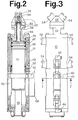
- a head part 52 is present as a further housing part, onto which the receptacles 54 with the check valves 16c and 18c are placed.
- the receptacles 54 for the check valves are standardized components and, as shown in particular in FIG. 3, are used for all check valves 16, 18.
- the head part 52 has a central bore 56, into which the piston 14 engages with a cylindrical extension 58, which in turn is penetrated by a centrally arranged blind bore 60.
- the length of the extension 58 is dimensioned such that the extension 58 still engages in the cylinder or central bore 56 even in the lowest travel position of the piston 14.
- the first effective piston surface 62 is formed by the end face of the piston 14 shown at the top in FIG. 1, which is laterally from the outer circumference of the piston 14 in the region of the guide bands 46 and the outer circumference of the cylindrical extension 58 is limited.
- the second effective piston surface 64 is arranged in the piston 14 like a shoulder below the upper guide band 46 and is delimited radially by the outer circumference of the piston 14 and the inner circumference of the housing 10 in the region of the chamber IV.
- the third piston surface 66 is formed by the tip of the extension 58 and is delimited radially from the outer circumference of the extension 58.
- the piston surface 62, 64, 66 of the piston 14, which acts on the compression as the pressure increases in the respective separation chamber III, IV, V, is made smaller than the piston surface in the respective previous pressure stage.
- the first piston surface 62 is thus larger than the second 64 and this in turn larger than the third piston surface 66.
- the part of the housing 10 which delimits the separation chambers III and IV and which has a pair of receptacles 54 with valves 16a, 18a and 16b, 18b at the end is sealed at the end with appropriate seals from the environment, which, as already described, is not the case for the housing part with the lateral recesses 32 shown at the bottom in FIG.
- a coolant (not shown) can be fed into the interior VII of the piston 14 and optionally into the further relief space VI.
- the oil and gas sides of the compressor are safely separated by the described pressure-relieved rooms VI and VII.
- the chamber VII achieves a minimally moving mass of the piston 14, which avoids the otherwise usual problems caused by the large inertial forces of the moving masses in known compressors.
- the cooling medium can act directly on the inside of the piston 14, which is particularly thermally stressed.
- the compression ratios, the clearance and the efficiency of the individual stages are designed accordingly.
- a transparent cap 68 is placed on the pointer device 42 that is moved during the operation of the compressor and that is firmly connected to the outer circumference of the housing 10.
- the fluid chambers II and I are alternately filled with hydraulic oil or emptied again, so that the piston 14 is moved back and forth in the axial direction.
- the pointer device of the anti-rotation device 40 alternately comes into proximity or comes into contact with the upper and lower limit switches 44 in the two dead center positions of the cylinder 14, which then, as part of the switching device (not shown), switches the reversing process of the hydraulic supply or discharge from the Activate fluid chambers I, II.
- the pointer device 42 consists of two collar-like neck parts, which are connected by means of a screw connection and a dovetail lock. the outer circumference of the piston 14 are clamped. The piston is guided via the pointer device 42, which are guided through two PTFE disks in one of the four longitudinal openings 32. This reliably prevents radial movement of the piston.
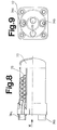
- a heat exchanger 72 which serves as a cooling device and which extracts the heat of the gas occurring during the compression process, can be connected to the connecting lines 20 in each case.
- the heat exchanger used for this purpose according to FIGS. 8 and 9 has connection points 74a, b which are connected to the respective connecting line 20 and which are used for introducing and discharging the gas into and out of the heat exchanger 72.
- the gas is passed through a coil 76 within the heat exchanger 72 and cooled in countercurrent by means of water which enters and exits the heat exchanger 72 via the connections 78.
- Such heat exchangers are well known to the specialist world, so that this will not be discussed any further.
- connection line 20 again made available to the compressor.
- measuring connections 79 are provided (FIG. 2), into which pressure indicators can be used to monitor the device. Such measurement indicators can also be used at other points in the device, if necessary.
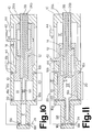
- FIG. 12 The left half of the picture between the two vertical dash lines relates to the switching process of the piston 14 from its bottom dead center position shown in FIG. 11 to the top dead center position according to FIG. 10, and in FIG. 12 the curve curves arranged to the right of it until the next vertical dash line curve Switching process from a representation according to FIG. 10 to FIG. 11 relate.
- both the volume and the pressure in the fluid chamber II decrease to zero and the fluid in the chamber II is discharged via the feed line 26a. Furthermore, the gas in the medium pressure chamber IV is brought into the high pressure chamber V via the outlet valve 18b and the inlet valve 16c. This results in chamber IV in the compression process shown on the left in FIG. 12 and in chamber V the gas is sucked in.
- the piston 14 moves again from its position shown in FIG. 10 to its former top dead center position as shown in FIG. 11. This movement is achieved in that fluid is pumped into the chamber II via the feed line 26a, whereas the chamber I is kept pressureless via the feed line 26b.
- the gas in the chamber III is compressed, which is pressed into the medium-pressure chamber IV via the outlet valve 18a, the connecting line 20 and the inlet valve 16b. So there is a suction process in the chamber IV as shown in the right half of Fig. 12. Furthermore, there is a compression process in the high pressure chamber V, so that in the second phase after switching the amount of gas compressed to the desired final pressure over the outlet valve 18c and the line 24 are discharged from the compressor. The gas removed can then be easily compressed to 400 bar. In addition to nitrogen gas, the compressor is also suitable for the compression of air. After the three-stage compression and suction process has ended, a new cycle begins as just described, ie the piston 14 moves again from its position shown in FIG.
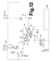
- the use of the device according to FIGS. 1 to 12 for an internal gas pressure system is shown below with reference to FIG. 13, the internal gas pressure system known per se being described only to the extent that it is necessary to explain the invention.
- the gas discharge from the compressor can be infinitely predetermined via a control of the fluid quantities that can be fed into the fluid chambers I, II.
- a continuously adjustable hydraulic pump 80 and / or an adjustable throttle 82 can be used.
- the final pressure on the gas side of the compressor depends only on the input pressure and the ratio of the compression chambers III to V, the final pressure being able to be regulated with the aid of the input pressure.
- the switching of the fluid chambers I to II is carried out via a 4/3-way valve 84, which is controlled accordingly via the limit switches 44 of the switching device (not shown).
- the gas quantities compressed to high pressure are delivered to a reservoir 88, for example in the form of a hydraulic reservoir, via the connecting line 24, which is secured by a check valve 86 of a known type.
- the gas is stored there and the gas quantities necessary for an injection molding process for the mold 90 can then be called up.
- the gas pressure system shown in FIG. 13 it is thus possible to continuously introduce gas into an injection mold via a hydraulic accumulator 88 reach, wherein the compressor is supplied via the supply line 22 from nitrogen reservoirs 92 with gas for loading the chamber III. Since the compressor according to the invention has a small structure and can also be produced inexpensively, it can be used in a particularly advantageous manner for all types of internal gas pressure systems.
Landscapes
- Engineering & Computer Science (AREA)
- Mechanical Engineering (AREA)
- General Engineering & Computer Science (AREA)
- Compressor (AREA)
- Compressors, Vaccum Pumps And Other Relevant Systems (AREA)
- Engine Equipment That Uses Special Cycles (AREA)
- Lubricants (AREA)
- Emulsifying, Dispersing, Foam-Producing Or Wetting Agents (AREA)
Applications Claiming Priority (3)
| Application Number | Priority Date | Filing Date | Title |
|---|---|---|---|
| DE4328264 | 1993-08-23 | ||
| DE4328264A DE4328264A1 (de) | 1993-08-23 | 1993-08-23 | Hydraulischer Gasverdichter |
| PCT/EP1994/002174 WO1995006204A1 (de) | 1993-08-23 | 1994-07-02 | Hydraulischer gasverdichter |
Publications (2)
| Publication Number | Publication Date |
|---|---|
| EP0715689A1 EP0715689A1 (de) | 1996-06-12 |
| EP0715689B1 true EP0715689B1 (de) | 1997-10-08 |
Family
ID=6495783
Family Applications (1)
| Application Number | Title | Priority Date | Filing Date |
|---|---|---|---|
| EP94924224A Expired - Lifetime EP0715689B1 (de) | 1993-08-23 | 1994-07-02 | Hydraulischer gasverdichter |
Country Status (14)
| Country | Link |
|---|---|
| US (1) | US5782612A (enExample) |
| EP (1) | EP0715689B1 (enExample) |
| JP (1) | JPH09502237A (enExample) |
| KR (1) | KR960704156A (enExample) |
| AT (1) | ATE159080T1 (enExample) |
| AU (1) | AU7457294A (enExample) |
| CA (1) | CA2165063A1 (enExample) |
| DE (2) | DE4328264A1 (enExample) |
| ES (1) | ES2107855T3 (enExample) |
| GR (1) | GR3025193T3 (enExample) |
| MY (1) | MY111012A (enExample) |
| TW (1) | TW247344B (enExample) |
| WO (1) | WO1995006204A1 (enExample) |
| ZA (1) | ZA946396B (enExample) |
Families Citing this family (27)
| Publication number | Priority date | Publication date | Assignee | Title |
|---|---|---|---|---|
| US6659730B2 (en) | 1997-11-07 | 2003-12-09 | Westport Research Inc. | High pressure pump system for supplying a cryogenic fluid from a storage tank |
| US5884488A (en) * | 1997-11-07 | 1999-03-23 | Westport Research Inc. | High pressure fuel supply system for natural gas vehicles |
| DE19840354C1 (de) * | 1998-09-04 | 2000-04-20 | Mannesmann Sachs Ag | Kompressor |
| IT1318801B1 (it) * | 2000-08-31 | 2003-09-10 | Nuovo Pignone Spa | Dispositivo per la regolazione continua della portata di gas trattatada un compressore alternativo. |
| DE102004061810A1 (de) * | 2004-12-22 | 2006-07-06 | Robert Bosch Gmbh | Kolbenpumpe mit wenigstens einem Stufenkolbenelement |
| US7779627B1 (en) * | 2009-02-05 | 2010-08-24 | Ries James D | Variable-displacement piston-cylinder device |
| US8359857B2 (en) * | 2009-05-22 | 2013-01-29 | General Compression, Inc. | Compressor and/or expander device |
| US8454321B2 (en) | 2009-05-22 | 2013-06-04 | General Compression, Inc. | Methods and devices for optimizing heat transfer within a compression and/or expansion device |
| WO2011079267A1 (en) | 2009-12-24 | 2011-06-30 | General Compression Inc. | System and methods for optimizing efficiency of a hydraulically actuated system |
| DE102010035164A1 (de) | 2010-08-23 | 2012-02-23 | Garri Alexandrow | Rotationskolben Gasverdichter |
| AU2011338574B2 (en) | 2010-12-07 | 2015-07-09 | General Compression, Inc. | Compressor and/or expander device with rolling piston seal |
| US8997475B2 (en) | 2011-01-10 | 2015-04-07 | General Compression, Inc. | Compressor and expander device with pressure vessel divider baffle and piston |
| WO2012097215A1 (en) | 2011-01-13 | 2012-07-19 | General Compression, Inc. | Systems, methods and devices for the management of heat removal within a compression and/or expansion device or system |
| CA2824798A1 (en) | 2011-01-14 | 2012-07-19 | General Compression, Inc. | Compressed gas storage and recovery system and method of operation |
| US8522538B2 (en) | 2011-11-11 | 2013-09-03 | General Compression, Inc. | Systems and methods for compressing and/or expanding a gas utilizing a bi-directional piston and hydraulic actuator |
| US8272212B2 (en) | 2011-11-11 | 2012-09-25 | General Compression, Inc. | Systems and methods for optimizing thermal efficiencey of a compressed air energy storage system |
| CN102678507B (zh) * | 2012-05-24 | 2015-03-18 | 陈人德 | 一种双作用液压注射型双气缸的抽真空与压缩装置 |
| CL2015001798A1 (es) * | 2015-06-22 | 2015-10-02 | Martinez Mauricio Eduardo Mulet | Cámaras concéntricas enumeradas desde la más externa; a la mas interna n; que se alimentan de un gas o liquido a presion, en medio de las cuales puede ir multiplicadores de presión simples, cada uno está formado por dos cilindros y émbolos unidos de manera que ambos cilindros-émbolos se abren o se cierran simultáneamente; de manera que uno hace de motor neumático o hidraulico que descarga a baja presion; interconectado al otro que hace de compresor o bomba, que descarga a alta presion. |
| CA2948018C (en) | 2016-09-22 | 2023-09-05 | I-Jack Technologies Incorporated | Lift apparatus for driving a downhole reciprocating pump |
| US10544783B2 (en) | 2016-11-14 | 2020-01-28 | I-Jack Technologies Incorporated | Gas compressor and system and method for gas compressing |
| US11339778B2 (en) | 2016-11-14 | 2022-05-24 | I-Jack Technologies Incorporated | Gas compressor and system and method for gas compressing |
| DE102018109443B4 (de) | 2018-04-19 | 2020-10-01 | Sera Gmbh | Kompressorvorrichtung und Kompressionsverfahren |
| WO2020064781A1 (de) * | 2018-09-24 | 2020-04-02 | Burckhardt Compression Ag | Labyrinthkolbenkompressor |
| DE102019006695B4 (de) * | 2019-09-24 | 2023-01-26 | G4A Gmbh | Hydraulische Kolbeneinrichtung, welche mindestens zum Zwecke einer Gasverdichtung verwendbar ist, Druckgasenergiewandlungseinrichtung, Druckgasenergiewandlungs-Wärmetauscher-Einrichtung, Druckgasenergiewandlungs-Wärmetauscher-Einrichtungs-Vorstufeneinrichtung und Druckgasenergiewandlungsvorrichtung |
| CA3074365A1 (en) | 2020-02-28 | 2021-08-28 | I-Jack Technologies Incorporated | Multi-phase fluid pump system |
| US11519403B1 (en) | 2021-09-23 | 2022-12-06 | I-Jack Technologies Incorporated | Compressor for pumping fluid having check valves aligned with fluid ports |
| US12571383B2 (en) | 2021-09-23 | 2026-03-10 | I-Jack Technologies Incorporated | Compresser for pumping fluid having check valves aligned with fluid ports |
Family Cites Families (13)
| Publication number | Priority date | Publication date | Assignee | Title |
|---|---|---|---|---|
| FR1180597A (fr) * | 1957-08-05 | 1959-06-05 | Air Equipement | Installation de compression d'air, plus particulièrement sur aéronefs |
| DE2146530A1 (de) * | 1971-09-17 | 1973-03-22 | Bbc Brown Boveri & Cie | Mehrstufiger, trockenlaufender hochdruckkolbenkompressor |
| US4111609A (en) * | 1975-10-22 | 1978-09-05 | Anton Braun | Multistage gas compressor |
| IT7904915U1 (it) * | 1979-08-28 | 1981-02-28 | Safe Srl | Compressore volumetrico alternativo polistadio. |
| US4334833A (en) * | 1980-10-28 | 1982-06-15 | Antonio Gozzi | Four-stage gas compressor |
| US4390322A (en) * | 1981-02-10 | 1983-06-28 | Tadeusz Budzich | Lubrication and sealing of a free floating piston of hydraulically driven gas compressor |
| CA1145728A (en) * | 1981-04-21 | 1983-05-03 | Antonio Gozzi | Three or four stage gas compressor |
| DE3410911A1 (de) * | 1983-04-06 | 1984-10-11 | Ernst Dipl.-Ing. 4600 Dortmund Korthaus | Kolbenpumpe |
| IT1187318B (it) * | 1985-02-22 | 1987-12-23 | Franco Zanarini | Compressore volumetrico alternato ad azionamento idraulico |
| DE3624227A1 (de) * | 1986-07-17 | 1988-01-28 | Timmer Pneumatik Gmbh | Pneumatisches pumpenaggregat |
| IT1213357B (it) * | 1986-10-13 | 1989-12-20 | Afros Spa | Unita' di pompaggio a pistoni coassiali. |
| DE4034442A1 (de) * | 1990-10-29 | 1992-04-30 | Karl Eickmann | Steuerung fuer hochdruck aggregat |
| US5238372A (en) * | 1992-12-29 | 1993-08-24 | The United States Of America As Represented By The Administrator Of The National Aeronautics And Space Administration | Cooled spool piston compressor |
-
1993
- 1993-08-23 DE DE4328264A patent/DE4328264A1/de not_active Withdrawn
- 1993-10-13 TW TW082108448A patent/TW247344B/zh active
-
1994
- 1994-07-02 CA CA002165063A patent/CA2165063A1/en not_active Abandoned
- 1994-07-02 WO PCT/EP1994/002174 patent/WO1995006204A1/de not_active Ceased
- 1994-07-02 AU AU74572/94A patent/AU7457294A/en not_active Abandoned
- 1994-07-02 DE DE59404288T patent/DE59404288D1/de not_active Expired - Fee Related
- 1994-07-02 US US08/549,734 patent/US5782612A/en not_active Expired - Fee Related
- 1994-07-02 EP EP94924224A patent/EP0715689B1/de not_active Expired - Lifetime
- 1994-07-02 ES ES94924224T patent/ES2107855T3/es not_active Expired - Lifetime
- 1994-07-02 JP JP7507286A patent/JPH09502237A/ja active Pending
- 1994-07-02 AT AT94924224T patent/ATE159080T1/de active
- 1994-07-29 MY MYPI94001975A patent/MY111012A/en unknown
- 1994-08-23 ZA ZA946396A patent/ZA946396B/xx unknown
-
1996
- 1996-02-16 KR KR1019960700916A patent/KR960704156A/ko not_active Abandoned
-
1997
- 1997-10-29 GR GR970402828T patent/GR3025193T3/el unknown
Also Published As
| Publication number | Publication date |
|---|---|
| KR960704156A (ko) | 1996-08-31 |
| WO1995006204A1 (de) | 1995-03-02 |
| CA2165063A1 (en) | 1995-03-02 |
| AU7457294A (en) | 1995-03-21 |
| GR3025193T3 (en) | 1998-02-27 |
| DE59404288D1 (de) | 1997-11-13 |
| DE4328264A1 (de) | 1995-03-02 |
| TW247344B (enExample) | 1995-05-11 |
| EP0715689A1 (de) | 1996-06-12 |
| JPH09502237A (ja) | 1997-03-04 |
| ZA946396B (en) | 1995-03-31 |
| MY111012A (en) | 1999-07-31 |
| ES2107855T3 (es) | 1997-12-01 |
| US5782612A (en) | 1998-07-21 |
| ATE159080T1 (de) | 1997-10-15 |
Similar Documents
| Publication | Publication Date | Title |
|---|---|---|
| EP0715689B1 (de) | Hydraulischer gasverdichter | |
| DE2462651C3 (de) | Betonpumpe | |
| EP0825348B1 (de) | Druckverstärker für Fluide, insbesondere für Hydraulikflüssigkeiten | |
| DE4138313C2 (de) | Radialkolbenpumpe | |
| DE2343611C2 (de) | Vorrichtung zum lastabhängigen Steuern einer hydrostatischen Verstellpumpe | |
| DE3617132A1 (de) | Schneckenkompressor mit zwillingsschieber | |
| DE2330607A1 (de) | Taumelscheibenpumpe mit veraenderbarem hubvolumen | |
| DE3617133A1 (de) | Steuerung fuer einen kompressor mit zwillingsschiebern | |
| DE19738779C2 (de) | Umsteuersystem für eine druckgetriebene Membranpumpe | |
| EP0311779A2 (de) | Hydraulische Steuereinrichtung für eine Presse | |
| EP1174617A2 (de) | Hydrostatische Axialkolbenmaschine | |
| DE3310437C2 (de) | Tieftemperatur-Kältemaschine | |
| DE3032430C2 (enExample) | ||
| EP1631746A1 (de) | Hydraulischer antrieb zum verlagern eines stellgliedes | |
| DE1922269A1 (de) | Summenleistungsregler | |
| EP0039418A1 (de) | Pressluftbetätigte Schmierpresse | |
| EP1274938A1 (de) | Schwingkolbenpumpe | |
| DE10138026C2 (de) | Pneumatikantriebssteuerung zum Steuern des Bewegungsablaufs von Pneumatikantrieben | |
| EP0850752A1 (de) | Mehrstationenpresse | |
| DE19543691A1 (de) | Schraubenverdichter | |
| DE3836076A1 (de) | Steuerteil fuer ein steuersystem zur steuerung des inneren volumens eines rotationskompressors | |
| DE3542926C2 (enExample) | ||
| EP0935069A2 (de) | Axialkolbenmaschine mit Mitteldrucköffnung in der Steuerscheibe | |
| DE19757157C2 (de) | Hydraulischer Linearantrieb | |
| DE4322614C2 (de) | Innenachsige Zahnradpumpe mit umlaufenden Förderräumen, vorzugsweise mit Trochoidenverzahnung |
Legal Events
| Date | Code | Title | Description |
|---|---|---|---|
| PUAI | Public reference made under article 153(3) epc to a published international application that has entered the european phase |
Free format text: ORIGINAL CODE: 0009012 |
|
| 17P | Request for examination filed |
Effective date: 19950801 |
|
| AK | Designated contracting states |
Kind code of ref document: A1 Designated state(s): AT BE DE ES FR GB GR IT LU NL PT |
|
| GRAG | Despatch of communication of intention to grant |
Free format text: ORIGINAL CODE: EPIDOS AGRA |
|
| 17Q | First examination report despatched |
Effective date: 19970225 |
|
| GRAH | Despatch of communication of intention to grant a patent |
Free format text: ORIGINAL CODE: EPIDOS IGRA |
|
| GRAH | Despatch of communication of intention to grant a patent |
Free format text: ORIGINAL CODE: EPIDOS IGRA |
|
| GRAA | (expected) grant |
Free format text: ORIGINAL CODE: 0009210 |
|
| AK | Designated contracting states |
Kind code of ref document: B1 Designated state(s): AT BE DE ES FR GB GR IT LU NL PT |
|
| REF | Corresponds to: |
Ref document number: 159080 Country of ref document: AT Date of ref document: 19971015 Kind code of ref document: T |
|
| ET | Fr: translation filed | ||
| GBT | Gb: translation of ep patent filed (gb section 77(6)(a)/1977) |
Effective date: 19971010 |
|
| REF | Corresponds to: |
Ref document number: 59404288 Country of ref document: DE Date of ref document: 19971113 |
|
| REG | Reference to a national code |
Ref country code: ES Ref legal event code: FG2A Ref document number: 2107855 Country of ref document: ES Kind code of ref document: T3 |
|
| ITF | It: translation for a ep patent filed | ||
| REG | Reference to a national code |
Ref country code: GR Ref legal event code: FG4A Free format text: 3025193 |
|
| REG | Reference to a national code |
Ref country code: PT Ref legal event code: SC4A Free format text: AVAILABILITY OF NATIONAL TRANSLATION Effective date: 19971215 |
|
| PLBE | No opposition filed within time limit |
Free format text: ORIGINAL CODE: 0009261 |
|
| STAA | Information on the status of an ep patent application or granted ep patent |
Free format text: STATUS: NO OPPOSITION FILED WITHIN TIME LIMIT |
|
| 26N | No opposition filed | ||
| PGFP | Annual fee paid to national office [announced via postgrant information from national office to epo] |
Ref country code: GB Payment date: 19990621 Year of fee payment: 6 |
|
| PGFP | Annual fee paid to national office [announced via postgrant information from national office to epo] |
Ref country code: PT Payment date: 19990625 Year of fee payment: 6 |
|
| PGFP | Annual fee paid to national office [announced via postgrant information from national office to epo] |
Ref country code: FR Payment date: 19990629 Year of fee payment: 6 |
|
| PGFP | Annual fee paid to national office [announced via postgrant information from national office to epo] |
Ref country code: GR Payment date: 19990705 Year of fee payment: 6 |
|
| PGFP | Annual fee paid to national office [announced via postgrant information from national office to epo] |
Ref country code: BE Payment date: 19990715 Year of fee payment: 6 |
|
| PGFP | Annual fee paid to national office [announced via postgrant information from national office to epo] |
Ref country code: ES Payment date: 19990721 Year of fee payment: 6 |
|
| PGFP | Annual fee paid to national office [announced via postgrant information from national office to epo] |
Ref country code: NL Payment date: 19990730 Year of fee payment: 6 Ref country code: LU Payment date: 19990730 Year of fee payment: 6 Ref country code: AT Payment date: 19990730 Year of fee payment: 6 |
|
| PGFP | Annual fee paid to national office [announced via postgrant information from national office to epo] |
Ref country code: DE Payment date: 19990802 Year of fee payment: 6 |
|
| PG25 | Lapsed in a contracting state [announced via postgrant information from national office to epo] |
Ref country code: LU Free format text: LAPSE BECAUSE OF NON-PAYMENT OF DUE FEES Effective date: 20000702 Ref country code: GB Free format text: LAPSE BECAUSE OF NON-PAYMENT OF DUE FEES Effective date: 20000702 Ref country code: AT Free format text: LAPSE BECAUSE OF NON-PAYMENT OF DUE FEES Effective date: 20000702 |
|
| PG25 | Lapsed in a contracting state [announced via postgrant information from national office to epo] |
Ref country code: ES Free format text: LAPSE BECAUSE OF NON-PAYMENT OF DUE FEES Effective date: 20000703 |
|
| PG25 | Lapsed in a contracting state [announced via postgrant information from national office to epo] |
Ref country code: GR Free format text: LAPSE BECAUSE OF NON-PAYMENT OF DUE FEES Effective date: 20000731 Ref country code: BE Free format text: LAPSE BECAUSE OF NON-PAYMENT OF DUE FEES Effective date: 20000731 |
|
| BERE | Be: lapsed |
Owner name: HYDAC TECHNOLOGY G.M.B.H. Effective date: 20000731 |
|
| PG25 | Lapsed in a contracting state [announced via postgrant information from national office to epo] |
Ref country code: PT Free format text: LAPSE BECAUSE OF NON-PAYMENT OF DUE FEES Effective date: 20010131 |
|
| PG25 | Lapsed in a contracting state [announced via postgrant information from national office to epo] |
Ref country code: NL Free format text: LAPSE BECAUSE OF NON-PAYMENT OF DUE FEES Effective date: 20010201 |
|
| GBPC | Gb: european patent ceased through non-payment of renewal fee |
Effective date: 20000702 |
|
| PG25 | Lapsed in a contracting state [announced via postgrant information from national office to epo] |
Ref country code: FR Free format text: LAPSE BECAUSE OF NON-PAYMENT OF DUE FEES Effective date: 20010330 |
|
| NLV4 | Nl: lapsed or anulled due to non-payment of the annual fee |
Effective date: 20010201 |
|
| REG | Reference to a national code |
Ref country code: FR Ref legal event code: ST |
|
| PG25 | Lapsed in a contracting state [announced via postgrant information from national office to epo] |
Ref country code: DE Free format text: LAPSE BECAUSE OF NON-PAYMENT OF DUE FEES Effective date: 20010501 |
|
| REG | Reference to a national code |
Ref country code: PT Ref legal event code: MM4A Free format text: LAPSE DUE TO NON-PAYMENT OF FEES Effective date: 20010131 |
|
| REG | Reference to a national code |
Ref country code: ES Ref legal event code: FD2A Effective date: 20020603 |
|
| PG25 | Lapsed in a contracting state [announced via postgrant information from national office to epo] |
Ref country code: IT Free format text: LAPSE BECAUSE OF NON-PAYMENT OF DUE FEES;WARNING: LAPSES OF ITALIAN PATENTS WITH EFFECTIVE DATE BEFORE 2007 MAY HAVE OCCURRED AT ANY TIME BEFORE 2007. THE CORRECT EFFECTIVE DATE MAY BE DIFFERENT FROM THE ONE RECORDED. Effective date: 20050702 |