EP0715276A2 - Méthode et appareil d'application de texture - Google Patents
Méthode et appareil d'application de texture Download PDFInfo
- Publication number
- EP0715276A2 EP0715276A2 EP95118163A EP95118163A EP0715276A2 EP 0715276 A2 EP0715276 A2 EP 0715276A2 EP 95118163 A EP95118163 A EP 95118163A EP 95118163 A EP95118163 A EP 95118163A EP 0715276 A2 EP0715276 A2 EP 0715276A2
- Authority
- EP
- European Patent Office
- Prior art keywords
- image
- texture
- polygon
- transformation
- points
- Prior art date
- Legal status (The legal status is an assumption and is not a legal conclusion. Google has not performed a legal analysis and makes no representation as to the accuracy of the status listed.)
- Withdrawn
Links
Images


Classifications
-
- G—PHYSICS
- G06—COMPUTING; CALCULATING OR COUNTING
- G06T—IMAGE DATA PROCESSING OR GENERATION, IN GENERAL
- G06T11/00—2D [Two Dimensional] image generation
- G06T11/40—Filling a planar surface by adding surface attributes, e.g. colour or texture
-
- G—PHYSICS
- G06—COMPUTING; CALCULATING OR COUNTING
- G06T—IMAGE DATA PROCESSING OR GENERATION, IN GENERAL
- G06T15/00—3D [Three Dimensional] image rendering
- G06T15/04—Texture mapping
-
- G—PHYSICS
- G06—COMPUTING; CALCULATING OR COUNTING
- G06T—IMAGE DATA PROCESSING OR GENERATION, IN GENERAL
- G06T3/00—Geometric image transformation in the plane of the image
- G06T3/40—Scaling the whole image or part thereof
- G06T3/4007—Interpolation-based scaling, e.g. bilinear interpolation
Definitions
- the present invention relates generally to texture mapping systems and, more particularly, to a new and improved method and apparatus for mapping texture which creates an image through a technique of texture mapping in an instrument using computer graphics such as video game apparatus, graphic computers and like instruments.
- an image generating unit has been used to create data of an image being outputted and displayed, i.e., displayed output image data appearing in TV receivers, monitor receivers, or CRT display units and the like.
- an exclusive image-formation unit between a CPU and a frame buffer so as to realize high-speed processing.
- the CPU does not directly access the frame buffer, but issues an image-formation instruction to the image-formation unit to prepare a fundamental figure, such as fundamental triangles and quadrangles. Then, the image-formation unit interprets the instruction issued from the CPU to form an image in the frame buffer.
- a minimum unit of a figure treated in the image-formation unit is referred to as a polygon or primitive.
- An instruction to form such a primitive image is referred to as an image-formation instruction.
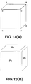
- the object OB may be divided into three parts, each part constituting a primitive and the CPU issues necessary image-formation instructions corresponding to each of those primitives to the image-formation unit.
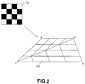
- Texture mapping is a technique for adding a surface texture pattern to a surface of the polygon forming the object, the texture pattern being a two-dimensional image independently prepared as a texture source image as shown.
- a known technique of high-speed texture mapping with a minimum circuit size is a so-called linear transformation.
- mapping or transformation to a shape other than parallelograms causes a diagonal image deformation.
- the present invention provides enhanced real-time texture mapping which produces a naturally-mapped realistic or solid image with a minimum calculation volume.
- a new and improved method and apparatus for mapping texture i.e., adding a texture image to a polygonal area forming a fundamental unit of information as to a three-dimensional image of an object to be graphically displayed, which includes a representative or representing point extracting means for extracting a representative or representing point from the polygonal area, a perspective-transformation means for performing a perspective transformation of the coordinates of the representing point having been extracted through the representing-point extracting means, and a linear-interpolation means for performing a linear interpolation between the representing points having been subjected to the perspective transformation through the perspective-transformation means, so that the image information, in which the texture image is added to the polygonal area, is obtained as an interpolation output issued from the linear-interpolation means.
- the representing-point extracting means extracts the representing points, the number of which varies in accordance with the size of the polygonal area.
- the representative or representing point is extracted by the representing point extracting means from an area of the polygonal shape forming a fundamental unit of three-dimensional image information, the information being provided for construction of an object to be displayed, coordinates of the thus extracted point are subjected to the perspective transformation through the perspective transformation means, and the linear interpolation between the representing points having been subjected to the perspective transformation through the perspective-transformation means is then performed.
- the representing point extracting means extracts the representing points, and the number of these points varies in accordance with the size of the polygonal area.
- the present invention satisfies a long existing need for enhanced image processing providing for simplified texture mapping transformation with reduced image distortion and minimal required calculation.
- a three-dimensional object OB is displayed, as shown in Fig. 13(B), the object OB is divided into three parts, i.e., primitives Pa, Pb and Pc, and the CPU issues necessary image-formation instructions corresponding to the primitives Pa, Pb, Pc to the image-formation unit.
- the texture mapping is a technique for adding a surface texture pattern Tx to a surface of the polygon forming the object, the texture pattern Tx being a two-dimensional image independently prepared as a texture source image as will be observed in Fig. 14.
- Fig. 14 there is shown an example of texture mapping applied to the surface of the object OB from Fig. 13(A).
- a known technique of high-speed texture mapping with a minimum circuit size is a so-called linear transformation.
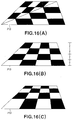
- texture mapping using the linear transformation for example, as shown in Fig.15, if a diced texture patter Tx is added to a surface of the polygon, an example of such mapping is shown in Fig. 16(A).
- mapping or transformation to a shape other than parallelograms causes a diagonal image deformation.
- a further technique for completely solving the above problem is a so-called perspective transformation.
- depth information (z) before the polygon is projected onto a computer screen.
- this calculation there is additionally required a division process for each of the points to be subjected to the texture mapping.
- a new and improved method and apparatus for mapping texture i.e., adding a texture image to a polygonal area forming a fundamental unit of information as to a three-dimensional image of an object to be graphically displayed, which includes a representative or representing point extracting means for extracting a representative or representing point from the polygonal area, a perspective-transformation means for performing a perspective transformation of the coordinates of the representing point having been extracted through the representing-point extracting means, and a linear-interpolation means for performing a linear interpolation between the representing points having been subjected to the perspective transformation through the perspective-transformation means, so that the image information, in which the texture image is added to the polygonal area, is obtained as an interpolation output issued from the linear-interpolation means.
- the representing-point extracting means extracts the representing points, the number of which varies in accordance with the size of the polygonal area.
- the representative or representing point is extracted by the representing point extracting means from an area of the polygonal shape forming a fundamental unit of three-dimensional image information, the information being provided for construction of an object to be displayed, coordinates of the thus extracted point are subjected to the perspective transformation through the perspective transformation means, and the linear interpolation between the representing points having been subjected to the perspective transformation through the perspective-transformation means is then performed.
- the representing point extracting means extracts the representing points, and the number of these points varies in accordance with the size of the polygonal area.
- the system of the present invention for performing the texture mapping is applied to a video game apparatus.
- a game is performed by retrieving and executing a game program stored in an auxiliary memory, such as optical disks and the like, in accordance with a user's instruction.
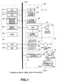
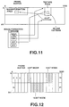
- the game apparatus has the overall system arrangement shown in Fig. 1.
- This video game system includes: a control system 50 comprising a central processing unit (i.e., CPU 51) and its peripheral devices; a graphic system 60 comprising a graphic processing unit (i.e., GPU 62) for forming an image in a frame buffer 63, a sound system 70 comprising a sound processing unit (i.e., an SPU); an optical-disk control subsystem 80 for controlling an optical disk forming an auxiliary memory, a communication control subsystem 90 for controlling both an input instruction issued from a controller operated by a user and an input/output signal issued from the auxiliary memory which stores the initial setting data of the game, and a bus 100 connected to the above components 50, 60, 70, 80, and 90.
- a control system 50 comprising a central processing unit (i.e., CPU 51) and its peripheral devices
- a graphic system 60 comprising a graphic processing unit (i.e., GPU 62) for forming an image in a frame buffer 63
- a sound system 70 comprising a sound processing unit
- the control system 50 is provided with the CPU 51, a peripheral-device controller 52 for performing necessary controls such as interrupt control, direct-memory access transfer control and like controls, a main memory 53 comprising a random access memory (i.e., RAM), and a read only memory (i.e., ROM 54) storing a program such as a so-called operating system and like programs for controlling the main memory 53, graphic system 60, sound system 70 and like systems.
- the CPU 51 executes the operating system stored in the ROM 54 to control the entire computer system, and typically comprises a 32-bit RISC CPU.
- the CPU 51 of the control system 50 executes the operating system stored in the ROM 54 to control the graphic system 60, sound system 70 and like systems.
- the CPU 51 initializes the entire computer system to do its performance check, and thereafter controls the optical-disk control subsystem 80 to execute a game program or the like stored in the optical disk.
- the CPU 51 controls the graphic system 60, sound system 70 and like systems in accordance with an instruction inputted by the user, so as to control an image in a display, sound effects and musical sounds in production.
- the graphic system 60 is provided with a geometry transfer engine (i.e., GTE 61) for performing a coordinate transformation and like processing, a CPU 62 for forming an image according to an image-formation instruction issued from the CPU 51, a frame buffer 63 for storing the image thus formed by the CPU 62, and, an image decoder 64 for decoding an image data, the image data having been compressed and encoded through a so-called orthogonal transformation, such as the well known discrete-cosine transformation and like transformations.
- GTE 61 geometry transfer engine
- GTE 61 for performing a coordinate transformation and like processing
- a CPU 62 for forming an image according to an image-formation instruction issued from the CPU 51
- a frame buffer 63 for storing the image thus formed by the CPU 62
- an image decoder 64 for decoding an image data, the image data having been compressed and encoded through a so-called orthogonal transformation, such as the well known discrete-cosine transformation and like transformations.
- the GTE 61 Upon receipt of an instruction or demand for computation issued from the CPU 51, the GTE 61 employs its parallel computing mechanism for executing a plurality of computations in parallel with each other and is capable of performing computations at high speed, which computations are of coordinate transformations, of light sources, of matrixes, or of vectors. More specifically, for example, in computation for realizing a so-called flat shading through which an image is formed into a triangular polygon with a single color, the GTE 61 executes computations of the coordinates at a maximum rate of approximately one and a half million polygons (1,500,000) per second, which enables the CPU 51 in the video game apparatus to reduce its load and permits the system to execute computations of the polygon's coordinates at high speed.
- the GPU 62 forms an image of the polygon and like shapes in the frame buffer 63.
- This GPU 62 is capable of forming up to three hundred and sixty thousand images of polygons per second.
- the CPU 51 has a series of image-formation instructions for generating single frame images in the main memory 53. These instructions are provided with their own addresses which identify the image-formation instructions to be executed.
- a controller 52 is provided for controlling the peripheral devices. This is a DMA controller which transfers the image-formation instructions from the main memory 53 to the CPU 62. Then, the CPU 62 executes the image-formation instructions issued from the DMA controller to obtain results which are then stored in the frame buffer 63.
- the DMA controller finds and executes a subsequent instruction by means of its address, after completion of transfer of one image-formation instruction.
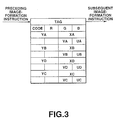
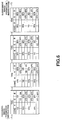
- an image-formation instruction "A" for performing such texture mapping of a quadrangle ABCD in image formation is provided as shown in Fig. 3.
- the GPU 62 forms an image of the polygon on the frame buffer 63, the image having been modified by the texture mapping through a linear transformation.
- the processing for forming the image of a single frame comprises a step S1 in which a transformation matrix is obtained. Then, in a subsequent step S2, when the image-formation instruction "A" and depth coordinates (ZA, ZB, ZD, ZC) in the instruction are given, each of the vertex coordinates (XA, YA), (XB, YB), (XD, YD), (XC, YC) is subjected to perspective transformation.
- step S3 sizes (delta X, delta Y) after completion of the perspective transformation are calculated based on the vertex coordinates (XA, YA), (XB, YB), (XD, YD), (XC, YC).
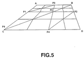
- step S4 for example, as shown in Fig. 5, the number of the representing points Pn and its locations are determined. As described above, by adequately varying the representing points Pn in number, it is possible to optimize a computation volume in the CPU.
- a subsequent set S5 it is judged whether or not the number of the representing points is more than one.
- the step S5 is followed by a subsequent step S6 in which the vertex coordinates (xn, yn) corresponding to coordinates (UPn, VPn) of the representing points Pn are determined through the perspective transformation.
- the quadrangle ABCD is divided into four small quadrangles APOP2P1, POBP3P2, P1P2P4C and P2P3DP4, each of which uses its representing points as its vertices, so that a series of respective image-formation instructions B0 to B4 are generated.
- previously calculated values or coordinates (XA, YA), (XB, YB), (XD, YD), (XC, YC) and (UA, VA), (UB, VB), (UD, VD), (UC, VC) are set as the vertex coordinates and the texture coordinates of each of sub-image formation instructions Bn.
- step S4 when the number of the representing points determined in the step S4 is one in the step S5, the step S5 is followed by a step S8 in which an image-formation instruction is immediately prepared.
- an image-formation instruction list is prepared by setting an address of a series of the sub-image formation instructions Bn in a tag of a series of the sub-image formation instructions Bn-1, and the thus prepared list is replaced with the original image-formation instruction "A".
- step S10 following the step S9, it is judged whether or not the processing is completed as to all of the polygons.
- the processing procedure returns to the step S2, i.e., the step S10 is followed by the step S2 in which additional perspective transformation of such remaining polygon's vertices is conducted.
- step S10 when it is found that no polygon remains unprocessed, the step S10 is followed by a step S11 in which the processing procedure waits for completion of image formation in a preceding frame.
- step S11 is followed by a step S12 in which the processing procedure commences to form the images from the top of the list.
- the GPU 62 determines a texture pixel other than the above-described representing points by performing a linear interpolation between the representing points having been subjected to the perspective transformation, so that the image is formed in the frame buffer 63, as shown in Fig. 8.
- the computation follows the processing procedure of the flow chart shown in Fig. 4, where the representing points are extracted from the polygons, each of which is used as a fundamental unit of three-dimensional image information forming an object to be displayed, the thus extracted representing points have their coordinates subjected to the perspective transformation, and the linear interpolation is conducted between such representing points having been subjected to the perspective transformation.
- This considerably reduces the required computation volume and is capable of producing a real-time solid and naturally mapped image.
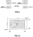
- the frame buffer 63 is constructed of a so-called dual-port RAM, and is capable of simultaneously performing image formation based on the instruction issued from the GPU 62, transfers from the main memory, and a data retrieving operation for display.
- a typical capacity of the frame buffer 63 is 1 MB which is capable of providing a 16-bit matrix having a size of 1024 (Horizontal) x 512 (Vertical) pixels.
- the frame buffer 63 in addition to the video-output display area is also provided with a CLUT area for storing a color look up table (CLUT) which the GPU 62 refers to in image formation of the polygons, and a texture area for storing a texture to be mapped or transformed into the polygons which have their images formed by the GPU 62 after completion of the coordinate transformation.
- CLUT color look up table
- texture area for storing a texture to be mapped or transformed into the polygons which have their images formed by the GPU 62 after completion of the coordinate transformation.
- Both the CLUT area and the texture area are dynamically modified as the display area is modified.
- the GPU 62 provides a pair of square-shaped areas "A", "B", and forms the image on one of the "B” areas while having the contents of the other "A” area displayed. After completion of the image formation, the square-shaped areas "A", "B” are replaced during the period of time of a vertical retrace so as to prevent rewriting operations from being displayed.
- the GPU 62 is capable of providing, in addition to the above-described flat shading, a Gouraud shading for determining a color of the polygon by performing interpolation based on colors of the vertices of the polygons, and a texture mapping for adding a texture stored in the texture area to the polygons.
- the GTE 61 is capable of computing up to approximately five hundred thousand of the polygon's coordinates per second.
- the GPU 62 supports ten frame modes shown in the following Table 1 when it issues the contents of a desired one of the square-shaped areas of the frame buffer 63 as its video output.
- Table 1 FRAME RESOLUTION Mode Standard Resolution Remarks Mode 0 256(H) x 240(V) Non-interlacing Mode 1 320 x 240 Mode 2 512 x 240 Mode 3 640 x 480 Mod 4 256 x 480 Interlacing Mode 5 320 x 480 Mode 6 512 x 480 Mode 7 640 x 480 Mode 8 384 x 240 Non-interlacing Mode 9 384 x 240 Interlacing
- the frame size i.e., the number of the pixels arranged on a CRT screen is variable.
- the display area of the screen can be specified by determining therein both a display beginning position with coordinates (DTX, DTY), and a display ending position with coordinates (DBX, DBY).
- the GPU 62 supports display-color modes comprising: a 15-bit mode with a 32,768-color display; and, a 24-bit mode with a 16,777,216-color display.
- the GPU 62 also supports a so-called spline image-formation function with a frame size of from 1 (H: Horizontal) x 1 (V: Vertical) to 256 (H) x 256 (V) dots, the number of the dots being arbitrarily selected.
- an image data or spline pattern being added to a spline is transferred to the frame buffer before execution of an image-formation command, and is stored in a non-display area of the frame buffer.
- one page i.e., texture page
- a size of the one texture page varies depending on the type of the mode. Further, as shown in Fig. 11, a location of the texture page in the frame buffer is determined by specifying a page number of a parameter called TSB in the image-formation command.
- spline patterns there are three types of color modes including a 4-bit CLUT mode, a 8-bit CLUT mode, and a 15-bit DIRECT mode.
- a 16-color spline image formation is realized by using the CLUT.
- a 8-bit CLUT mode a 256-color spline image formation is realized by using the CLUT.
- a 15-bit DIRECT mode a 32,768-color spline image formation is realized by directly using the 15-bit system.
- a color of each of the pixels is represented by a specific number which specifies one of the RGB values of the CLUT disposed on the frame buffer, the number of the RGB values being within a range of from 16 to 256. It is possible to specify the CLUT in spline units. Further, it is also possible to provide a separate CLUT for any spline.
- the image decoder 64 is controlled by the CPU 51 to decode the image data of still pictures or moving pictures which have been stored in the main memory 53, and the thus decoded data is stored in the main memory 53.
- Such reproduced image data is stored in the frame buffer 63 through the GPU 62, which makes it possible to use the reproduced image data as a background of a picture produced by the GPU 62.
- the sound system 70 comprises a sound processing unit (SPU) 71 which generates musical sounds, sound effects and the like upon receipt of an instruction issued from the CPU 51, a sound buffer 72 which is controlled by the SPU 71 to store a sound-wave data and like data therein, and a loudspeaker 73 for outputting the musical sounds, sound effects and the like generated by the SPU 71.
- SPU sound processing unit
- the SPU 71 is provided with an ADPCM decoding function for reproducing a sound data, the sound data being 16-bit sound data composed of 4-bit differential signals which have been subjected to processing of adaptive differential PCM (ADPCM), a reproducing function for generating the sound effects and the like by reproducing the sound-wave data stored in the sound buffer 72, and a modulator function for modulating the sound-wave data stored in the sound buffer 72 to reproduce the thus modulated sounds.
- ADPCM adaptive differential PCM
- the sound system 70 is capable of being used as a so-called sampling sound source for generating musical sounds, sound effects and the like, based on the wave-data stored in the sound buffer 72 when it receives an instruction issued from the CPU 51.
- the optical-disk control subsystem portion 80 comprises an optical-disk unit 81 for reproducing a program, data and the like stored in an optical disk, a decoder 82 for decoding a program, data and the like having been provided with, for example, an error correction code (ECC), a memory buffer 83 which temporarily stores reproduced data issued from the optical-disk unit 81 to facilitate retrieving of such data from the optical disk, and a sub-CPU 84 for control.
- ECC error correction code
- PCM data is a sound signal which has been subjected to an analog-to-digital conversion.
- Sound data stored as the ADPCM data (in which a difference, for example, in 16-bit digital data is represented as a 4-bit word and stored in this word) is decoded in the decoder 82, then supplied to the SPU 71 in which the supplied data is subjected to the analog-to-digital conversion, and thereafter used to drive the loudspeaker 73. Further, sound data stored as the PCM data (which is stored, for example, as a 16-bit digital data) is also decoded in the decoder 82, and then used to drive the loudspeaker 73.
- the communication control subsystem 90 is provided with a communication control unit 91 for controlling communications with the CPU 51 through a bus 100.
- a communication control unit 91 for controlling communications with the CPU 51 through a bus 100.
- a slot 93 connected with the controller 92 through which the user inputs his instruction, and a pair of card connectors 95A and 95B to which a pair of memory cards 94A and 94B for storing the game's setting data and the like data are connected, respectively.
- the controller 92 connected with the slot 93 for receiving the user's instruction is provided with, for example, 16 control keys.
- the controller 92 Upon receipt of an instruction issued from the communication control unit 91, the controller 92 supplies data of the control key's conditions to the CPU 51 through synchronous communication, sixty times a second.
- the communication control unit 91 issues the data of the control key's conditions from the controller 92 to the CPU 51.
- the user's instruction is inputted to the CPU 51, so that the CPU 51 executes a necessary operation according to the user's instruction.
- the CPU 51 issues such data being stored to the communication control unit 91. Then, the unit 91 stores the data in one of the memory cards 93A and 93B which are connected with the card connectors 95A and 95B, respectively.
- a protective circuit to prevent electrical failures.
- the memory cards 93A, 93B are separated from the bus 100. Consequently, the memory cards 93A, 93B are capable of being mounted and dismounted in a condition in which the power switch of the main unit is turned on. Therefore, when the memory lacks capacity, it is possible to mount a new one of the cards without turning off the power switch of the main unit. Consequently, there is no fear that necessary game data may be lost. Hence, it is possible to store such necessary game data in the new one of the memory cards being mounted.
- Each of the memory cards 93A, 93B is constructed of a flash memory which permits random access, requires no backup power source, and has a microcomputer incorporated therein.
- the memory cards 93A, 93B are connected with the card connectors 95A, 95B, electric power is supplied from the main unit to the microcomputer through the card connectors.
- the memory cards 93A, 93B are recognized as file devices by an application, the file devices being identified by the use of hexadecimal numbers with two figures, such numbers specifying both the ports and the card connectors.
- Each of the memory cards 93A, 93B has an automatic initializing function which is performed when a file is opened.
- the microcomputer When the memory cards 93A, 93B are connected with the card connectors 95A, 95B so that the main unit supplies electric power to these memory cards, the microcomputer initially sets an internal state of each of the memory cards at a "no-communication" state, and thereafter establishes communications with the memory cards through the communication control unit 91.
- the CPU 51 in the main unit side tests an internal state of the microcomputer incorporated in each of the memory cards 93A, 93B which have been connected with the card connectors 95A, 95B.
- a new one of the memory cards 93A, 93B is recognized to be communicated, so that file control data relative to the new one of the memory cards 93A, 93B, for example, information as to file names, file sizes, slot numbers and the like, together with status information, are retrieved.
- each of the memory cards 93A, 93B is constructed of a flash memory which is randomly accessible and requires no backup power supply, it is possible for the memory cards 93A, 93B to store the data for a substantially indefinite period of time.
- this video game apparatus is provided with a parallel input/output (PIO) 101 and a serial input/output (SIO) 102, both of which are connected with the bus 100.
- PIO parallel input/output
- SIO serial input/output
- the video game apparatus is capable of communicating with the peripheral devices through the parallel input/output (PIO) 101, and also capable of communicating with other video game apparatuses through the serial input/output (SIO) 102.
- PIO parallel input/output
- SIO serial input/output
- a representing-point extracting means extracts a representing point from an area of a polygon which forms a fundamental unit of three-dimensional image information of an object to be displayed on the computer screen
- a perspective transformation means performs a perspective transformation of the coordinates of the representing point having been extracted by the representing-point extracting means
- a linear interpolation between the representing points having been subjected to the perspective transformation through the perspective-transformation means is performed.
- the representing-point extracting means extracts the representing points which varies in number in accordance with the size of the polygonal area, and which optimizes the computation volume to make it possible to obtain a solid and naturally-mapped image on the computer screen.
- the present invention satisfies a long existing need for enhanced image processing providing for simplified texture mapping transformation with reduced image distortion and minimal required calculation.
Applications Claiming Priority (2)
| Application Number | Priority Date | Filing Date | Title |
|---|---|---|---|
| JP300026/94 | 1994-12-02 | ||
| JP30002694A JP3647487B2 (ja) | 1994-12-02 | 1994-12-02 | テクスチャマッピング装置 |
Publications (2)
| Publication Number | Publication Date |
|---|---|
| EP0715276A2 true EP0715276A2 (fr) | 1996-06-05 |
| EP0715276A3 EP0715276A3 (fr) | 1996-07-24 |
Family
ID=17879819
Family Applications (1)
| Application Number | Title | Priority Date | Filing Date |
|---|---|---|---|
| EP95118163A Withdrawn EP0715276A3 (fr) | 1994-12-02 | 1995-11-17 | Méthode et appareil d'application de texture |
Country Status (7)
| Country | Link |
|---|---|
| US (1) | US5933148A (fr) |
| EP (1) | EP0715276A3 (fr) |
| JP (1) | JP3647487B2 (fr) |
| KR (1) | KR960025239A (fr) |
| CN (1) | CN1110022C (fr) |
| AU (1) | AU704617B2 (fr) |
| CA (1) | CA2163839A1 (fr) |
Cited By (6)
| Publication number | Priority date | Publication date | Assignee | Title |
|---|---|---|---|---|
| WO1998029837A1 (fr) * | 1996-12-30 | 1998-07-09 | Cirrus Logic, Inc. | Procede de calcul de parametres de mappage de texture |
| WO1998029839A1 (fr) * | 1996-12-30 | 1998-07-09 | Cirrus Logic, Inc. | Texturage perspectif non homogene du second ordre par utilisation de parametres d'interpolation lineaire |
| WO2002050778A1 (fr) * | 2000-12-21 | 2002-06-27 | Active Online Gmbh | Procede et systeme electronique de traitement d'images, s'utilisant notamment pour mapper des objets graphiques |
| WO2007075249A1 (fr) * | 2005-12-21 | 2007-07-05 | Microsoft Corporation | Rééchantillonnage de texture au moyen d'un processeur |
| EP2034445A1 (fr) | 2007-09-05 | 2009-03-11 | Osmosys S.A. | Procédé pour dessiner des formes géométriques |
| EP2034444A1 (fr) * | 2007-09-05 | 2009-03-11 | Osmosys S.A. | Procédé de rotation d'images |
Families Citing this family (77)
| Publication number | Priority date | Publication date | Assignee | Title |
|---|---|---|---|---|
| US7859551B2 (en) | 1993-10-15 | 2010-12-28 | Bulman Richard L | Object customization and presentation system |
| JPH10198822A (ja) * | 1997-01-10 | 1998-07-31 | Sharp Corp | 画像合成装置 |
| US6061066A (en) * | 1998-03-23 | 2000-05-09 | Nvidia Corporation | Method and apparatus for creating perspective correct graphical images |
| US6040837A (en) * | 1998-04-22 | 2000-03-21 | Ati Technologies, Inc. | Method and apparatus for space variable texture filtering |
| JPH11331700A (ja) | 1998-05-15 | 1999-11-30 | Sony Corp | 画像処理装置および画像処理方法 |
| US7071949B1 (en) * | 1998-11-18 | 2006-07-04 | Microsoft Corporation | View dependent tiled textures |
| CA2369879A1 (fr) | 1999-04-09 | 2000-10-19 | Sony Computer Entertainment Inc. | Procede et dispositif d'execution d'une transformation de perspective |
| US6396502B1 (en) | 1999-10-15 | 2002-05-28 | Hewlett-Packard Company | System and method for implementing accumulation buffer operations in texture mapping hardware |
| US6822658B1 (en) | 1999-10-25 | 2004-11-23 | Intel Corporation | Rendering a silhouette edge |
| US6798411B1 (en) * | 1999-10-29 | 2004-09-28 | Intel Corporation | Image processing |
| US7180523B1 (en) | 2000-03-31 | 2007-02-20 | Intel Corporation | Trimming surfaces |
| US7061501B1 (en) | 2000-11-07 | 2006-06-13 | Intel Corporation | Rendering a pencil-sketch image |
| US7034791B1 (en) * | 2000-12-14 | 2006-04-25 | Gary Odom | Digital video display employing minimal visual conveyance |
| US7116330B2 (en) | 2001-02-28 | 2006-10-03 | Intel Corporation | Approximating motion using a three-dimensional model |
| US7190374B2 (en) * | 2001-02-28 | 2007-03-13 | Intel Corporation | Shading polygons from a three-dimensional model |
| US6980206B2 (en) * | 2001-06-07 | 2005-12-27 | Intel Corporation | Rendering a three-dimensional model using a dither pattern |
| US6924804B2 (en) * | 2001-09-25 | 2005-08-02 | Intel Corporation | Reducing the resolution of bones in a three-dimensional model |
| JP2003117241A (ja) * | 2001-10-11 | 2003-04-22 | Sega Corp | キャラクタ配置方法、データ管理方法及びモデル形成方法 |
| US6906724B2 (en) * | 2001-10-17 | 2005-06-14 | Lntel Corporation | Generating a shadow for a three-dimensional model |
| US7548241B2 (en) * | 2002-01-04 | 2009-06-16 | Intel Corporation | Determining a node path through a node graph |
| US7301547B2 (en) | 2002-03-22 | 2007-11-27 | Intel Corporation | Augmented reality system |
| US7146297B2 (en) * | 2002-03-27 | 2006-12-05 | Intel Corporation | Detecting collisions of three-dimensional models |
| US6975318B2 (en) * | 2002-06-25 | 2005-12-13 | Intel Corporation | Polygon binning process for tile-based rendering |
| US6982715B2 (en) * | 2002-07-26 | 2006-01-03 | Intel Corporation | Mesh compression process |
| TWI238975B (en) * | 2003-02-20 | 2005-09-01 | Via Tech Inc | Method of performing cubic mapping with texturing |
| US7681112B1 (en) | 2003-05-30 | 2010-03-16 | Adobe Systems Incorporated | Embedded reuse meta information |
| US7076735B2 (en) * | 2003-07-21 | 2006-07-11 | Landmark Graphics Corporation | System and method for network transmission of graphical data through a distributed application |
| US7231632B2 (en) * | 2004-04-16 | 2007-06-12 | Apple Computer, Inc. | System for reducing the number of programs necessary to render an image |
| US7248265B2 (en) * | 2004-04-16 | 2007-07-24 | Apple Inc. | System and method for processing graphics operations with graphics processing unit |
| US7847800B2 (en) * | 2004-04-16 | 2010-12-07 | Apple Inc. | System for emulating graphics operations |
| US8134561B2 (en) | 2004-04-16 | 2012-03-13 | Apple Inc. | System for optimizing graphics operations |
| US8704837B2 (en) * | 2004-04-16 | 2014-04-22 | Apple Inc. | High-level program interface for graphics operations |
| US7636489B2 (en) * | 2004-04-16 | 2009-12-22 | Apple Inc. | Blur computation algorithm |
| US8130237B2 (en) * | 2004-06-24 | 2012-03-06 | Apple Inc. | Resolution independent user interface design |
| US7397964B2 (en) * | 2004-06-24 | 2008-07-08 | Apple Inc. | Gaussian blur approximation suitable for GPU |
| US8068103B2 (en) * | 2004-06-24 | 2011-11-29 | Apple Inc. | User-interface design |
| US8566732B2 (en) | 2004-06-25 | 2013-10-22 | Apple Inc. | Synchronization of widgets and dashboards |
| US7546543B2 (en) | 2004-06-25 | 2009-06-09 | Apple Inc. | Widget authoring and editing environment |
| US8302020B2 (en) | 2004-06-25 | 2012-10-30 | Apple Inc. | Widget authoring and editing environment |
| US8239749B2 (en) | 2004-06-25 | 2012-08-07 | Apple Inc. | Procedurally expressing graphic objects for web pages |
| US7761800B2 (en) | 2004-06-25 | 2010-07-20 | Apple Inc. | Unified interest layer for user interface |
| US7490295B2 (en) | 2004-06-25 | 2009-02-10 | Apple Inc. | Layer for accessing user interface elements |
| US8453065B2 (en) | 2004-06-25 | 2013-05-28 | Apple Inc. | Preview and installation of user interface elements in a display environment |
| US7652678B2 (en) * | 2004-06-25 | 2010-01-26 | Apple Inc. | Partial display updates in a windowing system using a programmable graphics processing unit |
| US20050285866A1 (en) * | 2004-06-25 | 2005-12-29 | Apple Computer, Inc. | Display-wide visual effects for a windowing system using a programmable graphics processing unit |
| US7158143B2 (en) * | 2004-12-03 | 2007-01-02 | Via Technologies, Inc. | Fast algorithm for anisotropic texture sampling |
| CN100365660C (zh) * | 2004-12-13 | 2008-01-30 | 北京中星微电子有限公司 | 一种图像放大插值的方法 |
| US7227551B2 (en) * | 2004-12-23 | 2007-06-05 | Apple Inc. | Manipulating text and graphic appearance |
| US8140975B2 (en) | 2005-01-07 | 2012-03-20 | Apple Inc. | Slide show navigation |
| JP2006202083A (ja) * | 2005-01-21 | 2006-08-03 | Seiko Epson Corp | 画像データ生成装置、および印刷装置 |
| JP4613636B2 (ja) * | 2005-02-21 | 2011-01-19 | セイコーエプソン株式会社 | 印刷データ出力装置、および印刷データ出力方法 |
| US8543931B2 (en) | 2005-06-07 | 2013-09-24 | Apple Inc. | Preview including theme based installation of user interface elements in a display environment |
| US7954064B2 (en) | 2005-10-27 | 2011-05-31 | Apple Inc. | Multiple dashboards |
| US9104294B2 (en) | 2005-10-27 | 2015-08-11 | Apple Inc. | Linked widgets |
| US7743336B2 (en) | 2005-10-27 | 2010-06-22 | Apple Inc. | Widget security |
| US7752556B2 (en) | 2005-10-27 | 2010-07-06 | Apple Inc. | Workflow widgets |
| US8543824B2 (en) | 2005-10-27 | 2013-09-24 | Apple Inc. | Safe distribution and use of content |
| US7707514B2 (en) | 2005-11-18 | 2010-04-27 | Apple Inc. | Management of user interface elements in a display environment |
| JP4747881B2 (ja) * | 2006-02-27 | 2011-08-17 | セイコーエプソン株式会社 | 演算処理装置によるデータ変換方法、テクスチャの作成方法、プログラム、記録媒体、及びプロジェクタ。 |
| US8155682B2 (en) * | 2006-05-05 | 2012-04-10 | Research In Motion Limited | Handheld electronic device including automatic mobile phone number management, and associated method |
| US7953260B2 (en) * | 2006-06-09 | 2011-05-31 | Craniosim Solutions, Inc. | Predicting movement of soft tissue of the face in response to movement of underlying bone |
| US8869027B2 (en) | 2006-08-04 | 2014-10-21 | Apple Inc. | Management and generation of dashboards |
| US8253731B2 (en) | 2006-11-27 | 2012-08-28 | Designin Corporation | Systems, methods, and computer program products for home and landscape design |
| US8117558B2 (en) * | 2006-11-27 | 2012-02-14 | Designin Corporation | Converting web content into two-dimensional CAD drawings and three-dimensional CAD models |
| US20080126021A1 (en) * | 2006-11-27 | 2008-05-29 | Ramsay Hoguet | Converting web content into texture mapping objects |
| US8122370B2 (en) * | 2006-11-27 | 2012-02-21 | Designin Corporation | Visual bookmarks for home and landscape design |
| US8954871B2 (en) | 2007-07-18 | 2015-02-10 | Apple Inc. | User-centric widgets and dashboards |
| US8667415B2 (en) | 2007-08-06 | 2014-03-04 | Apple Inc. | Web widgets |
| US8156467B2 (en) | 2007-08-27 | 2012-04-10 | Adobe Systems Incorporated | Reusing components in a running application |
| US8176466B2 (en) | 2007-10-01 | 2012-05-08 | Adobe Systems Incorporated | System and method for generating an application fragment |
| US9619304B2 (en) | 2008-02-05 | 2017-04-11 | Adobe Systems Incorporated | Automatic connections between application components |
| US7973798B2 (en) * | 2008-03-31 | 2011-07-05 | Microsoft Corporation | Inverse texture synthesis |
| US8656293B1 (en) | 2008-07-29 | 2014-02-18 | Adobe Systems Incorporated | Configuring mobile devices |
| CN102543040B (zh) * | 2008-12-15 | 2014-10-15 | 富士通株式会社 | 用在图形光栅扫描中的凸多边形插值方法和系统 |
| USD721717S1 (en) | 2011-10-31 | 2015-01-27 | Kings Mountain International Inc. | Display screen or portion thereof with a graphical user interface |
| US11127106B2 (en) | 2019-06-28 | 2021-09-21 | Intel Corporation | Runtime flip stability characterization |
| US11409341B2 (en) | 2019-10-01 | 2022-08-09 | Intel Corporation | Repeating graphics render pattern detection |
Citations (2)
| Publication number | Priority date | Publication date | Assignee | Title |
|---|---|---|---|---|
| US5307450A (en) * | 1991-02-19 | 1994-04-26 | Silicon Graphics, Inc. | Z-subdivision for improved texture mapping |
| JPH06301792A (ja) * | 1993-04-15 | 1994-10-28 | Sony Corp | テクスチャマッピング装置 |
Family Cites Families (18)
| Publication number | Priority date | Publication date | Assignee | Title |
|---|---|---|---|---|
| US4580134A (en) * | 1982-11-16 | 1986-04-01 | Real Time Design, Inc. | Color video system using data compression and decompression |
| JPS628193A (ja) * | 1985-07-04 | 1987-01-16 | インタ−ナショナル ビジネス マシ−ンズ コ−ポレ−ション | カラー画像表示装置 |
| US4823120A (en) * | 1986-09-12 | 1989-04-18 | Apple Computer, Inc. | Enhanced video graphics controller |
| US4811124A (en) * | 1987-07-24 | 1989-03-07 | Advanced Micro Devices, Inc. | Defect skipping mechanism for disk drives |
| US5091717A (en) * | 1989-05-01 | 1992-02-25 | Sun Microsystems, Inc. | Apparatus for selecting mode of output in a computer system |
| US5224208A (en) * | 1990-03-16 | 1993-06-29 | Hewlett-Packard Company | Gradient calculation for texture mapping |
| JP2950346B2 (ja) * | 1991-03-25 | 1999-09-20 | ソニー株式会社 | 画像データのデコード方法及びそのデコーダ回路 |
| JP3158370B2 (ja) * | 1991-07-12 | 2001-04-23 | ソニー株式会社 | ディスクデータ再生装置 |
| JPH0567179A (ja) * | 1991-09-10 | 1993-03-19 | Hitachi Ltd | 形状データ処理方法及び装置 |
| US5291468A (en) * | 1991-09-16 | 1994-03-01 | International Business Machines Corporation | Method and apparatus for synchronizing the readout of a sequential media device with a separate clocked device |
| GB2270243B (en) * | 1992-08-26 | 1996-02-28 | Namco Ltd | Image synthesizing system |
| JPH06111495A (ja) * | 1992-09-30 | 1994-04-22 | Sony Corp | データ再生装置 |
| JP3243883B2 (ja) * | 1993-04-12 | 2002-01-07 | ソニー株式会社 | 記録又は再生装置 |
| JPH07146952A (ja) * | 1993-11-22 | 1995-06-06 | Konami Kk | 3次元画像処理装置 |
| JP3064799B2 (ja) * | 1994-03-29 | 2000-07-12 | ヤマハ株式会社 | テクスチャマッピング装置 |
| US5594846A (en) * | 1994-12-19 | 1997-01-14 | Sun Microsystems, Inc. | Perspective correction of texture in graphics by adaptive approximation |
| US5649082A (en) * | 1995-03-20 | 1997-07-15 | Silicon Graphics, Inc. | Efficient method and apparatus for determining texture coordinates for lines and polygons |
| US5719599A (en) * | 1995-06-07 | 1998-02-17 | Seiko Epson Corporation | Method and apparatus for efficient digital modeling and texture mapping |
-
1994
- 1994-12-02 JP JP30002694A patent/JP3647487B2/ja not_active Expired - Lifetime
-
1995
- 1995-11-17 EP EP95118163A patent/EP0715276A3/fr not_active Withdrawn
- 1995-11-27 CA CA002163839A patent/CA2163839A1/fr not_active Abandoned
- 1995-11-28 KR KR1019950044125A patent/KR960025239A/ko not_active Application Discontinuation
- 1995-11-30 US US08/565,719 patent/US5933148A/en not_active Expired - Lifetime
- 1995-12-01 CN CN95120025A patent/CN1110022C/zh not_active Expired - Lifetime
- 1995-12-01 AU AU40209/95A patent/AU704617B2/en not_active Expired
Patent Citations (2)
| Publication number | Priority date | Publication date | Assignee | Title |
|---|---|---|---|---|
| US5307450A (en) * | 1991-02-19 | 1994-04-26 | Silicon Graphics, Inc. | Z-subdivision for improved texture mapping |
| JPH06301792A (ja) * | 1993-04-15 | 1994-10-28 | Sony Corp | テクスチャマッピング装置 |
Non-Patent Citations (4)
| Title |
|---|
| EUROGRAPHICS, 4 - 8 September 1989, AMSTERDAM, pages 257-268, XP000132231 BENNIS AND GAGALOWICZ: "hierarchical texture synthesis on 3-d surfaces" * |
| LANSDALE R.C: "Texture Mapping and Resampling for Computer Graphics", Master Thesis submitted at the Department of Electrical Engineering, University of Toronto, Toronto, Canada, January 1991 * |
| machine translation of JP-A-6 301 792 from http://www1.ipdl.jpo.go.jp/PA1/cgi-bin/PA1I NDEX * |
| SMPTE JOURNAL, vol. 100, no. 3, March 1991, US, pages 162-166, XP000178490 VIGNEAUX E.A.: "a real time video mapping and manipulation" * |
Cited By (6)
| Publication number | Priority date | Publication date | Assignee | Title |
|---|---|---|---|---|
| WO1998029837A1 (fr) * | 1996-12-30 | 1998-07-09 | Cirrus Logic, Inc. | Procede de calcul de parametres de mappage de texture |
| WO1998029839A1 (fr) * | 1996-12-30 | 1998-07-09 | Cirrus Logic, Inc. | Texturage perspectif non homogene du second ordre par utilisation de parametres d'interpolation lineaire |
| WO2002050778A1 (fr) * | 2000-12-21 | 2002-06-27 | Active Online Gmbh | Procede et systeme electronique de traitement d'images, s'utilisant notamment pour mapper des objets graphiques |
| WO2007075249A1 (fr) * | 2005-12-21 | 2007-07-05 | Microsoft Corporation | Rééchantillonnage de texture au moyen d'un processeur |
| EP2034445A1 (fr) | 2007-09-05 | 2009-03-11 | Osmosys S.A. | Procédé pour dessiner des formes géométriques |
| EP2034444A1 (fr) * | 2007-09-05 | 2009-03-11 | Osmosys S.A. | Procédé de rotation d'images |
Also Published As
| Publication number | Publication date |
|---|---|
| CA2163839A1 (fr) | 1996-06-03 |
| KR960025239A (ko) | 1996-07-20 |
| EP0715276A3 (fr) | 1996-07-24 |
| CN1150675A (zh) | 1997-05-28 |
| AU4020995A (en) | 1996-06-13 |
| US5933148A (en) | 1999-08-03 |
| JP3647487B2 (ja) | 2005-05-11 |
| CN1110022C (zh) | 2003-05-28 |
| AU704617B2 (en) | 1999-04-29 |
| JPH08161510A (ja) | 1996-06-21 |
Similar Documents
| Publication | Publication Date | Title |
|---|---|---|
| US5933148A (en) | Method and apparatus for mapping texture | |
| US5949409A (en) | Image processing in which the image is divided into image areas with specific color lookup tables for enhanced color resolution | |
| AU702762B2 (en) | Method of producing image data, image data processing apparatus, and recording medium | |
| US8144158B2 (en) | Display system having floating point rasterization and floating point framebuffering | |
| EP1353296B1 (fr) | Image avec profondeur de champ utilisant des données image du tampon Z et le mélange alpha | |
| JP3886184B2 (ja) | 画像データの処理方法および画像処理装置 | |
| EP0715278B1 (fr) | Méthode pour produire des données d'image et support d'enregistrement associé | |
| US5760782A (en) | Method and apparatus for generating images | |
| JPH08161511A (ja) | 画像生成装置 | |
| MXPA95004904A (en) | Method for producing image data, image data processing device and regis medium | |
| JPH06342468A (ja) | コンピュータグラフィックス画像圧縮符号化システム |
Legal Events
| Date | Code | Title | Description |
|---|---|---|---|
| PUAI | Public reference made under article 153(3) epc to a published international application that has entered the european phase |
Free format text: ORIGINAL CODE: 0009012 |
|
| AK | Designated contracting states |
Kind code of ref document: A2 Designated state(s): DE ES FR GB SE |
|
| PUAL | Search report despatched |
Free format text: ORIGINAL CODE: 0009013 |
|
| AK | Designated contracting states |
Kind code of ref document: A3 Designated state(s): DE ES FR GB SE |
|
| 17P | Request for examination filed |
Effective date: 19961218 |
|
| 17Q | First examination report despatched |
Effective date: 20000127 |
|
| RAP1 | Party data changed (applicant data changed or rights of an application transferred) |
Owner name: SONY COMPUTER ENTERTAINMENT INC. |
|
| STAA | Information on the status of an ep patent application or granted ep patent |
Free format text: STATUS: THE APPLICATION IS DEEMED TO BE WITHDRAWN |
|
| 18D | Application deemed to be withdrawn |
Effective date: 20020227 |