EP0715144B1 - Plattenstapel für einen Wärmetauscher - Google Patents
Plattenstapel für einen Wärmetauscher Download PDFInfo
- Publication number
- EP0715144B1 EP0715144B1 EP95402548A EP95402548A EP0715144B1 EP 0715144 B1 EP0715144 B1 EP 0715144B1 EP 95402548 A EP95402548 A EP 95402548A EP 95402548 A EP95402548 A EP 95402548A EP 0715144 B1 EP0715144 B1 EP 0715144B1
- Authority
- EP
- European Patent Office
- Prior art keywords
- plates
- zone
- bundle
- fluids
- heat exchange
- Prior art date
- Legal status (The legal status is an assumption and is not a legal conclusion. Google has not performed a legal analysis and makes no representation as to the accuracy of the status listed.)
- Expired - Lifetime
Links
- 239000012530 fluid Substances 0.000 claims description 54
- 230000007704 transition Effects 0.000 claims description 9
- 125000006850 spacer group Chemical group 0.000 claims description 2
- 239000002184 metal Substances 0.000 claims 1
- 241000422252 Cales Species 0.000 description 2
- 235000021183 entrée Nutrition 0.000 description 2
- 229910000679 solder Inorganic materials 0.000 description 2
- 229910001220 stainless steel Inorganic materials 0.000 description 2
- 239000010935 stainless steel Substances 0.000 description 2
- 238000003466 welding Methods 0.000 description 2
- 239000011324 bead Substances 0.000 description 1
- 239000000463 material Substances 0.000 description 1
Images


Classifications
-
- F—MECHANICAL ENGINEERING; LIGHTING; HEATING; WEAPONS; BLASTING
- F28—HEAT EXCHANGE IN GENERAL
- F28F—DETAILS OF HEAT-EXCHANGE AND HEAT-TRANSFER APPARATUS, OF GENERAL APPLICATION
- F28F3/00—Plate-like or laminated elements; Assemblies of plate-like or laminated elements
- F28F3/02—Elements or assemblies thereof with means for increasing heat-transfer area, e.g. with fins, with recesses, with corrugations
- F28F3/04—Elements or assemblies thereof with means for increasing heat-transfer area, e.g. with fins, with recesses, with corrugations the means being integral with the element
- F28F3/042—Elements or assemblies thereof with means for increasing heat-transfer area, e.g. with fins, with recesses, with corrugations the means being integral with the element in the form of local deformations of the element
- F28F3/046—Elements or assemblies thereof with means for increasing heat-transfer area, e.g. with fins, with recesses, with corrugations the means being integral with the element in the form of local deformations of the element the deformations being linear, e.g. corrugations
-
- F—MECHANICAL ENGINEERING; LIGHTING; HEATING; WEAPONS; BLASTING
- F28—HEAT EXCHANGE IN GENERAL
- F28D—HEAT-EXCHANGE APPARATUS, NOT PROVIDED FOR IN ANOTHER SUBCLASS, IN WHICH THE HEAT-EXCHANGE MEDIA DO NOT COME INTO DIRECT CONTACT
- F28D9/00—Heat-exchange apparatus having stationary plate-like or laminated conduit assemblies for both heat-exchange media, the media being in contact with different sides of a conduit wall
- F28D9/0062—Heat-exchange apparatus having stationary plate-like or laminated conduit assemblies for both heat-exchange media, the media being in contact with different sides of a conduit wall the conduits for one heat-exchange medium being formed by spaced plates with inserted elements
-
- F—MECHANICAL ENGINEERING; LIGHTING; HEATING; WEAPONS; BLASTING
- F28—HEAT EXCHANGE IN GENERAL
- F28F—DETAILS OF HEAT-EXCHANGE AND HEAT-TRANSFER APPARATUS, OF GENERAL APPLICATION
- F28F3/00—Plate-like or laminated elements; Assemblies of plate-like or laminated elements
- F28F3/02—Elements or assemblies thereof with means for increasing heat-transfer area, e.g. with fins, with recesses, with corrugations
- F28F3/04—Elements or assemblies thereof with means for increasing heat-transfer area, e.g. with fins, with recesses, with corrugations the means being integral with the element
- F28F3/042—Elements or assemblies thereof with means for increasing heat-transfer area, e.g. with fins, with recesses, with corrugations the means being integral with the element in the form of local deformations of the element
- F28F3/044—Elements or assemblies thereof with means for increasing heat-transfer area, e.g. with fins, with recesses, with corrugations the means being integral with the element in the form of local deformations of the element the deformations being pontual, e.g. dimples
-
- Y—GENERAL TAGGING OF NEW TECHNOLOGICAL DEVELOPMENTS; GENERAL TAGGING OF CROSS-SECTIONAL TECHNOLOGIES SPANNING OVER SEVERAL SECTIONS OF THE IPC; TECHNICAL SUBJECTS COVERED BY FORMER USPC CROSS-REFERENCE ART COLLECTIONS [XRACs] AND DIGESTS
- Y10—TECHNICAL SUBJECTS COVERED BY FORMER USPC
- Y10S—TECHNICAL SUBJECTS COVERED BY FORMER USPC CROSS-REFERENCE ART COLLECTIONS [XRACs] AND DIGESTS
- Y10S165/00—Heat exchange
- Y10S165/355—Heat exchange having separate flow passage for two distinct fluids
- Y10S165/356—Plural plates forming a stack providing flow passages therein
- Y10S165/393—Plural plates forming a stack providing flow passages therein including additional element between heat exchange plates
- Y10S165/394—Corrugated heat exchange plate
Definitions
- the subject of the present invention is a bundle of plates for heat exchanger.
- Heat exchangers are generally of two types.
- the first type of heat exchangers has a bundle of "U" shaped tubes or a bundle of straight tubes, in which a fluid circulates.
- the second type of heat exchangers includes a bundle of plates arranged contiguously and parallel to each other.
- the plates made of thin sheets have edges with smooth surface and a central part provided with corrugations by which they are in contact with each other the others and by which they delimit a double circulation circuit of two independent fluids and against the current from one end to the other of the exchanger.
- the plates are connected to each other at their longitudinal edges by means of connection constituted for example by spacers longitudinal fixed together by a weld wall waterproof extending over the entire length and over the entire beam height.
- the plates determine, from a share, a central area of transfer and exchange between the fluids and, on the other hand, at each end of the beam, a superimposition of inputs and outlets for these fluids.
- each plate has particular undulations distributed in directions determined on the surface of said plate and which determine the central transfer and exchange area thermal as well as the inputs and outputs.
- Inputs and outputs are therefore formed by a superposition of crisscrossing undulations, creating cross section variations fluids and thereby generating disturbances in the flow of these fluids.
- the object of the invention is to provide a bundle of plates for heat exchangers which allows avoid the disadvantages mentioned above.
- the subject of the invention is therefore a bundle of plates for a heat exchanger, of the type comprising a stack of heat exchange plates metallic, parallel to each other and each having smooth edges and a central part provided with corrugations to form with the associated plates a double circulation circuit of two independent and counter-current fluids, the plates being connected to each other at the level of their longitudinal edges by connecting means and determining, on the one hand, a transfer area and heat exchange between fluids and, on the other hand, at their free ends, an area of inputs and outputs of said fluids, formed by the ends of the heat exchange plates between which are inserted independent plates and provided with reliefs to ensure the distribution of fluids in the heat exchange zone, characterized in that each plate provided with reliefs comprises at minus a zone for guiding one of the fluids towards the corresponding circuit and a low traffic area of this fluid, separated from the guide zone by at minus a transition zone allowing passage of said fluid between these two zones.
- the bundle of plates for heat exchanger is consists of three parts, a central part A and two end parts, respectively B and C.
- the central part A which constitutes the zone of transfer and heat exchange proper consists of a stack of plates 10 parallel to each other to others.
- Each plate 10 consists of a sheet fine, usually made of stainless steel, or any other sufficiently ductile material and comprises, so classic, longitudinal and transverse edges to smooth surface and, between these edges, undulations 11.
- the plates 10 determine between them a double circulation circuit of two independent fluids. Heat exchange fluids circulate longitudinally from one end to the other of the beam and against a current.
- the plates 10 are assembled with each other at their longitudinal edges by means of link constituted for example by bars 12 extending over the entire length of the longitudinal edges of said plates 10 and by a layer of solder 13 deposited over the entire length and over the entire height of each lateral surface of the beam to form a wall waterproof welding.
- the stack of plates 10 is placed between an upper sheet 14 and a lower sheet 15 extending over the entire surface of the plates 10 and whose edges are connected to the edges of said plates 10 by the solder layers 13.
- this bundle has at each of its ends, a inlet and outlet area of said fluids which constitute the end portions B and C of said bundle.
- these fluid inlet and outlet areas are formed by a stack of the flat ends 10a of the heat exchange plates 10 between which are inserted plates 21 provided with reliefs, these plates 10 constituting the heat transfer and exchange zone between fluids.
- the set of flat ends 10a of heat exchange plates 10 and plates 21 provided reliefs determine at each end of the beam and at each circuit in central zone A, at minus one inlet (a) of one of the fluids and at least one outlet (b) from the other of said fluids.
- Distribution of inputs (a) and outputs (b) at each end of the beam is a function of fluid and heat exchange characteristics to get between these fluids.
- the inputs and outputs include at upper beam level an entry (a) for one of the fluids, at the level below, two outlets (b) for the other of said fluids and so on until lower level of this beam.
- the plates 21 provided with reliefs comprise at the level of their longitudinal edges of the shims 22 for fixing and spacing with the flat ends 10a of the plates heat exchange 10.
- Each longitudinal edge of the plates 21 fitted with reliefs is fixed on a wedge 22 for example by a weld bead 23.
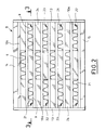
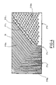
- each plate 21 provided with reliefs includes at least one guide zone from one of the fluids to the corresponding circuit and a zone of low circulation of this fluid, separated from the guidance zone by at least one transition zone allowing the passage of said fluid between these two zones.
- the plate 21 provided with reliefs comprises a zone 21a for guiding one of the fluids towards the corresponding circuit and a low traffic area 21b of this fluid, separated from the guide zone 21a by at least one transition zone 21c allowing passage of said fluid between these two zones 21a and 21b.
- the guide zone 21a of the plate 21 has continuous corrugations 210a which form with the flat ends 10a of the exchange plates 10 thermal of the corresponding fluid circulation channels of constant section and oriented towards the circuit in which this fluid circulates.
- the low circulation area 21b of the plate 21 has pins 210b for maintaining the spacing with the flat ends 10a of the plates 10 associated heat exchange.
- the transition zone 21c includes longitudinally discontinuous corrugations 210c forming passages 211c between the guide zone 21a and the zone 21b of low circulation.
- the transition zone 21c ensures the passage a small amount of fluid from the guide zone 21a towards the low traffic area 21b so that the latter is bathed in a small amount of fluid and that thus a total stagnation of this fluid be avoided in this area.
- the bundle of plates according to the invention therefore has, at each of its ends, entry and exit zones formed by the ends planes of the heat exchange plates between which independent plates are fitted with reliefs which form cross sectional fluids constant which allows to obtain a uniform flow fluids thus improving the efficiency of the beam plates.
Landscapes
- Engineering & Computer Science (AREA)
- Physics & Mathematics (AREA)
- Thermal Sciences (AREA)
- Mechanical Engineering (AREA)
- General Engineering & Computer Science (AREA)
- Heat-Exchange Devices With Radiators And Conduit Assemblies (AREA)
Claims (8)
- Plattensatz für einen Wärmetauscher der Art, der einen Stapel von metallischen Wärmetauscherplatten (10) aufweist, die parallel zueinander liegen und je Ränder mit glatter Oberfläche und einen mit Welligkeiten (11) versehenen zentralen Bereich aufweisen, um mit den zugeordneten Wärmetauscherplatten (10) einen doppelten Kreislauf für die Zirkulation zweier unabhängiger und gegenströmender Fluide zu bilden, wobei die Platten (10) an ihren Längsrändern über Verbindungsmittel (13) miteinander verbunden sind und einerseits eine Transfer- und Wärmetauscherzone zwischen den Fluiden und andererseits an ihren freien Enden eine Zone mit Eingängen und Ausgängen für diese Fluide aufweisen, die von den ebenen Enden (10a) der Wärmetauscherplatten (10) gebildet werden, zwischen die unabhängige Platten (21) eingefügt sind, welche Reliefs aufweisen, um die Verteilung der Fluide in der Wärmetauscherzone zu gewährleisten, dadurch gekennzeichnet, daß jede mit Reliefs versehene Platte (21) mindestens eine Zone (21a) zur Führung eines der Fluide zum entsprechenden Kreislauf hin und eine Zone (21b) geringer Zirkulation dieses Fluids aufweist, die von der Führungszone (21a) durch mindestens eine Übergangszone (21c) getrennt ist, die den Übergang des Fluids zwischen diesen beiden Zonen (21a, 21b) erlaubt.
- Plattensatz nach Anspruch 1, dadurch gekennzeichnet, daß die Gesamtheit der Enden (10a) der Wärmetauscherplatten und der mit Reliefs versehenen Platten (21) an jedem Ende des Plattensatzes übereinander angeordnet mindestens einen Eingang (a) für eines der Fluide und mindestens einen Ausgang (b) für das andere Fluid bildet.
- Plattensatz nach Anspruch 1, dadurch gekennzeichnet, daß die Führungszone (21a) durchgehende Welligkeiten (210a) aufweist.
- Plattensatz nach Anspruch 3, dadurch gekennzeichnet, daß die durchgehenden Welligkeiten (210a) der Führungszone (21a) mit den Enden (10a) der Wärmetauscherplatten (10) Umlaufkanäle für die Fluide bilden, deren Querschnitt konstant ist, und die zu den entsprechenden Kreisläufen hin ausgerichtet sind.
- Plattensatz nach Anspruch 1, dadurch gekennzeichnet, daß die Zone (21b) geringer Zirkulation Stifte (210b) für die Aufrechterhaltung des Abstands zu den ebenen Enden (10a) der zugeordneten Wärmetauscherplatten (10) aufweist.
- Plattensatz nach Anspruch 1, dadurch gekennzeichnet, daß die Übergangszone (21c) in Längsrichtung unterbrochene Welligkeiten (210c) aufweist, die Ubergänge (211c) zwischen der Führungszone (21a) und der Zone (21b) geringer Zirkulation bilden.
- Plattensatz nach einem beliebigen der vorhergehenden Ansprüche, dadurch gekennzeichnet, daß die mit Reliefs versehenen Platten (21) an ihren Längsrändern AbstandsstÜck (22) zur Befestigung und zur Abstandshaltung zu den ebenen Enden (10a) der Wärmetauscherplatten (10) aufweisen.
- Plattensatz nach Anspruch 7, dadurch gekennzeichnet, daß jede von den ebenen Enden (10a) der Wärmetauscherplatten (10), den mit Reliefs versehenen Platten (21) und den Abstandsstücken (22) gebildete Einheit dicht und fest mit den die Übergangs- und Austauschzone bildenden Längsrändern der Platten (10) mit Hilfe der Verbindungsmittel (13) dieser Platten (10) verbunden ist.
Applications Claiming Priority (2)
| Application Number | Priority Date | Filing Date | Title |
|---|---|---|---|
| FR9414231A FR2727505A1 (fr) | 1994-11-28 | 1994-11-28 | Faisceau de plaques pour un echangeur thermique |
| FR9414231 | 1994-11-28 |
Publications (2)
| Publication Number | Publication Date |
|---|---|
| EP0715144A1 EP0715144A1 (de) | 1996-06-05 |
| EP0715144B1 true EP0715144B1 (de) | 1999-04-07 |
Family
ID=9469211
Family Applications (1)
| Application Number | Title | Priority Date | Filing Date |
|---|---|---|---|
| EP95402548A Expired - Lifetime EP0715144B1 (de) | 1994-11-28 | 1995-11-14 | Plattenstapel für einen Wärmetauscher |
Country Status (5)
| Country | Link |
|---|---|
| US (1) | US5584341A (de) |
| EP (1) | EP0715144B1 (de) |
| JP (1) | JP3691136B2 (de) |
| DE (1) | DE69508892T2 (de) |
| FR (1) | FR2727505A1 (de) |
Families Citing this family (18)
| Publication number | Priority date | Publication date | Assignee | Title |
|---|---|---|---|---|
| FR2760656B1 (fr) * | 1997-03-17 | 1999-06-04 | Packinox Sa | Reacteur catalytique a plaques |
| US6194609B1 (en) | 1997-06-30 | 2001-02-27 | Bp Amoco Corporation | Crystallization in a plate heat exchanger |
| US5931212A (en) * | 1997-07-15 | 1999-08-03 | Wayne-Dalton Corp. | Motorized operator for doors |
| FR2769082B1 (fr) * | 1997-09-29 | 1999-12-24 | Packinox Sa | Plaques d'un faisceau de plaques d'echange thermique et procedes de fabrication d'une telle plaque |
| US6233824B1 (en) | 1999-10-08 | 2001-05-22 | Carrier Corporation | Cylindrical heat exchanger |
| US6408941B1 (en) | 2001-06-29 | 2002-06-25 | Thermal Corp. | Folded fin plate heat-exchanger |
| US6769479B2 (en) * | 2002-06-11 | 2004-08-03 | Solar Turbines Inc | Primary surface recuperator sheet |
| DE10247264A1 (de) * | 2002-10-10 | 2004-04-29 | Behr Gmbh & Co. | Plattenwärmeübertrager in Stapelbauweise |
| US6920920B2 (en) * | 2003-04-16 | 2005-07-26 | Catacel Corporation | Heat exchanger |
| US7017655B2 (en) | 2003-12-18 | 2006-03-28 | Modine Manufacturing Co. | Forced fluid heat sink |
| US7159649B2 (en) * | 2004-03-11 | 2007-01-09 | Thermal Corp. | Air-to-air heat exchanger |
| KR100938802B1 (ko) * | 2009-06-11 | 2010-01-27 | 국방과학연구소 | 마이크로채널 열교환기 |
| US8375635B2 (en) | 2009-08-26 | 2013-02-19 | Richard Hellinga | Apparatus for opening and closing overhead sectional doors |
| DE102010031561A1 (de) | 2010-07-20 | 2012-01-26 | Behr Gmbh & Co. Kg | System zur Nutzung von Abwärme eines Verbrennungsmotors |
| CN105793662B (zh) * | 2013-12-10 | 2020-03-10 | 舒瑞普国际股份公司 | 具有改进的流动的热交换器 |
| EP3150952A1 (de) * | 2015-10-02 | 2017-04-05 | Alfa Laval Corporate AB | Wärmetauschplatte und plattenwärmetauscher |
| US10823511B2 (en) | 2017-06-26 | 2020-11-03 | Raytheon Technologies Corporation | Manufacturing a heat exchanger using a material buildup process |
| EP3473961B1 (de) | 2017-10-20 | 2020-12-02 | Api Heat Transfer, Inc. | Wärmetauscher |
Family Cites Families (11)
| Publication number | Priority date | Publication date | Assignee | Title |
|---|---|---|---|---|
| US2875986A (en) * | 1957-04-12 | 1959-03-03 | Ferrotherm Company | Heat exchanger |
| US3282334A (en) * | 1963-04-29 | 1966-11-01 | Trane Co | Heat exchanger |
| US3380517A (en) * | 1966-09-26 | 1968-04-30 | Trane Co | Plate type heat exchangers |
| US3860065A (en) * | 1970-04-08 | 1975-01-14 | Trane Co | Distributor for plate type heat exchanger having side headers |
| US3759323A (en) * | 1971-11-18 | 1973-09-18 | Caterpillar Tractor Co | C-flow stacked plate heat exchanger |
| US4450903A (en) * | 1982-09-20 | 1984-05-29 | The Trane Company | Plate type heat exchanger with transverse hollow slotted bar |
| DE3330254A1 (de) * | 1983-08-22 | 1985-03-14 | Farkas, György, Dipl.-Ing., 3340 Wolfenbüttel | Waermetauscher fuer belueftung |
| JPS60256792A (ja) * | 1984-06-04 | 1985-12-18 | Hitachi Ltd | 積層形熱交換器 |
| GB8506415D0 (en) * | 1985-03-12 | 1985-04-11 | Atkin H S | Room ventilator |
| US4844151A (en) * | 1986-12-23 | 1989-07-04 | Sundstrand Corporation | Heat exchanger apparatus |
| TW216453B (en) * | 1992-07-08 | 1993-11-21 | Air Prod & Chem | Integrated plate-fin heat exchange reformation |
-
1994
- 1994-11-28 FR FR9414231A patent/FR2727505A1/fr active Granted
-
1995
- 1995-11-14 DE DE69508892T patent/DE69508892T2/de not_active Expired - Lifetime
- 1995-11-14 EP EP95402548A patent/EP0715144B1/de not_active Expired - Lifetime
- 1995-11-22 JP JP30477195A patent/JP3691136B2/ja not_active Expired - Lifetime
- 1995-11-28 US US08/563,469 patent/US5584341A/en not_active Expired - Lifetime
Also Published As
| Publication number | Publication date |
|---|---|
| JPH08219677A (ja) | 1996-08-30 |
| DE69508892T2 (de) | 1999-08-12 |
| FR2727505B1 (de) | 1997-02-14 |
| FR2727505A1 (fr) | 1996-05-31 |
| DE69508892D1 (de) | 1999-05-12 |
| JP3691136B2 (ja) | 2005-08-31 |
| US5584341A (en) | 1996-12-17 |
| EP0715144A1 (de) | 1996-06-05 |
Similar Documents
| Publication | Publication Date | Title |
|---|---|---|
| EP0715144B1 (de) | Plattenstapel für einen Wärmetauscher | |
| EP0186592B1 (de) | Plattenwärmetauscher | |
| EP0740949A1 (de) | Plattenwärmetauscher | |
| EP1012522B1 (de) | Wärmetauscherbündel und verfahren zu dessen verschweissung und herstellung | |
| EP0571263B1 (de) | Plattenstapel für Wärmetauscher und Verfahren zu dessen Zusammenbau | |
| KR100217515B1 (ko) | 적층형 열교환기의 열교환용 도관 및 그 제조방법 | |
| EP1206672B1 (de) | Wärmetauscher und dazugehöriges wärmeaustauschmodul | |
| EP2856060B1 (de) | Plattenwärmetauscher für homogene fluidströmungen zwischen leitungen | |
| FR2806469A1 (fr) | PROCEDE d4ASSEMBLAGE DES PLAQUES D'UN FAISCEAU DE PLAQUES ET FAISCEAU DE PLAQUES REALISE PAR UN TEL PROCEDE | |
| FR2824895A1 (fr) | Ailette ondulee a persiennes pour echangeur de chaleur a plaques, et echangeur a plaques muni de telles ailettes | |
| EP1426722A1 (de) | Wärmetauscherplatte und Plattenwärmetauscher | |
| EP0706634B1 (de) | Geschweisster plattenwärmetauscher und verfahren zum verschweissen von platten zu einem plattenwärmetauscher | |
| FR2862747A1 (fr) | Plaque d'echangeur de chaleur, et cet echangeur | |
| US4190038A (en) | Solar heater | |
| JP2004516448A (ja) | 溝付きスペーサバーを備えたフィン付き管ブロック型熱交換器 | |
| FR2793875A1 (fr) | Echangeur thermique a plaques | |
| JPS61122493A (ja) | プレ−ト式熱交換器 | |
| EP1019665A1 (de) | Platten eines wärmetauscherplattenstapels | |
| WO1993004330A1 (fr) | Echangeur a plaques | |
| CA2917539C (fr) | Dispositif d'echange thermique et procede de fabrication d'un tel dispositif | |
| FR2738906A1 (fr) | Faisceau de plaques pour un echangeur thermique et echangeur thermique comportant un tel faisceau de plaques | |
| JPS63113298A (ja) | プレ−トフイン型熱交換器及びその製造方法 | |
| EP0865818B1 (de) | Plattenreaktor für katalytische Reaktion | |
| FR2526931A1 (fr) | Radiateur-panneau | |
| FR2757257A1 (fr) | Echangeur thermique a plaques |
Legal Events
| Date | Code | Title | Description |
|---|---|---|---|
| PUAI | Public reference made under article 153(3) epc to a published international application that has entered the european phase |
Free format text: ORIGINAL CODE: 0009012 |
|
| AK | Designated contracting states |
Kind code of ref document: A1 Designated state(s): BE DE ES FR GB IT NL |
|
| 17P | Request for examination filed |
Effective date: 19961126 |
|
| 17Q | First examination report despatched |
Effective date: 19980306 |
|
| GRAG | Despatch of communication of intention to grant |
Free format text: ORIGINAL CODE: EPIDOS AGRA |
|
| GRAG | Despatch of communication of intention to grant |
Free format text: ORIGINAL CODE: EPIDOS AGRA |
|
| GRAH | Despatch of communication of intention to grant a patent |
Free format text: ORIGINAL CODE: EPIDOS IGRA |
|
| GRAH | Despatch of communication of intention to grant a patent |
Free format text: ORIGINAL CODE: EPIDOS IGRA |
|
| GRAA | (expected) grant |
Free format text: ORIGINAL CODE: 0009210 |
|
| AK | Designated contracting states |
Kind code of ref document: B1 Designated state(s): BE DE ES FR GB IT NL |
|
| PG25 | Lapsed in a contracting state [announced via postgrant information from national office to epo] |
Ref country code: IT Free format text: LAPSE BECAUSE OF FAILURE TO SUBMIT A TRANSLATION OF THE DESCRIPTION OR TO PAY THE FEE WITHIN THE PRESCRIBED TIME-LIMIT;WARNING: LAPSES OF ITALIAN PATENTS WITH EFFECTIVE DATE BEFORE 2007 MAY HAVE OCCURRED AT ANY TIME BEFORE 2007. THE CORRECT EFFECTIVE DATE MAY BE DIFFERENT FROM THE ONE RECORDED. Effective date: 19990407 Ref country code: ES Free format text: THE PATENT HAS BEEN ANNULLED BY A DECISION OF A NATIONAL AUTHORITY Effective date: 19990407 |
|
| 111L | Licence recorded |
Free format text: 981021 0100 ZIEPACK, SOCIETE ANONYME |
|
| REF | Corresponds to: |
Ref document number: 69508892 Country of ref document: DE Date of ref document: 19990512 |
|
| GBT | Gb: translation of ep patent filed (gb section 77(6)(a)/1977) |
Effective date: 19990709 |
|
| PG25 | Lapsed in a contracting state [announced via postgrant information from national office to epo] |
Ref country code: BE Free format text: LAPSE BECAUSE OF NON-PAYMENT OF DUE FEES Effective date: 19991130 |
|
| PLBE | No opposition filed within time limit |
Free format text: ORIGINAL CODE: 0009261 |
|
| STAA | Information on the status of an ep patent application or granted ep patent |
Free format text: STATUS: NO OPPOSITION FILED WITHIN TIME LIMIT |
|
| 26N | No opposition filed | ||
| BERE | Be: lapsed |
Owner name: PACKINOX Effective date: 19991130 |
|
| REG | Reference to a national code |
Ref country code: GB Ref legal event code: IF02 |
|
| PGFP | Annual fee paid to national office [announced via postgrant information from national office to epo] |
Ref country code: GB Payment date: 20141118 Year of fee payment: 20 Ref country code: DE Payment date: 20141113 Year of fee payment: 20 Ref country code: FR Payment date: 20141125 Year of fee payment: 20 |
|
| PGFP | Annual fee paid to national office [announced via postgrant information from national office to epo] |
Ref country code: NL Payment date: 20141024 Year of fee payment: 20 |
|
| REG | Reference to a national code |
Ref country code: DE Ref legal event code: R071 Ref document number: 69508892 Country of ref document: DE |
|
| REG | Reference to a national code |
Ref country code: NL Ref legal event code: MK Effective date: 20151113 |
|
| REG | Reference to a national code |
Ref country code: GB Ref legal event code: PE20 Expiry date: 20151113 |
|
| PG25 | Lapsed in a contracting state [announced via postgrant information from national office to epo] |
Ref country code: GB Free format text: LAPSE BECAUSE OF EXPIRATION OF PROTECTION Effective date: 20151113 |