EP0715144B1 - Stack of plates for a heat exchanger - Google Patents
Stack of plates for a heat exchanger Download PDFInfo
- Publication number
- EP0715144B1 EP0715144B1 EP95402548A EP95402548A EP0715144B1 EP 0715144 B1 EP0715144 B1 EP 0715144B1 EP 95402548 A EP95402548 A EP 95402548A EP 95402548 A EP95402548 A EP 95402548A EP 0715144 B1 EP0715144 B1 EP 0715144B1
- Authority
- EP
- European Patent Office
- Prior art keywords
- plates
- zone
- bundle
- fluids
- heat exchange
- Prior art date
- Legal status (The legal status is an assumption and is not a legal conclusion. Google has not performed a legal analysis and makes no representation as to the accuracy of the status listed.)
- Expired - Lifetime
Links
Images


Classifications
-
- F—MECHANICAL ENGINEERING; LIGHTING; HEATING; WEAPONS; BLASTING
- F28—HEAT EXCHANGE IN GENERAL
- F28F—DETAILS OF HEAT-EXCHANGE AND HEAT-TRANSFER APPARATUS, OF GENERAL APPLICATION
- F28F3/00—Plate-like or laminated elements; Assemblies of plate-like or laminated elements
- F28F3/02—Elements or assemblies thereof with means for increasing heat-transfer area, e.g. with fins, with recesses, with corrugations
- F28F3/04—Elements or assemblies thereof with means for increasing heat-transfer area, e.g. with fins, with recesses, with corrugations the means being integral with the element
- F28F3/042—Elements or assemblies thereof with means for increasing heat-transfer area, e.g. with fins, with recesses, with corrugations the means being integral with the element in the form of local deformations of the element
- F28F3/046—Elements or assemblies thereof with means for increasing heat-transfer area, e.g. with fins, with recesses, with corrugations the means being integral with the element in the form of local deformations of the element the deformations being linear, e.g. corrugations
-
- F—MECHANICAL ENGINEERING; LIGHTING; HEATING; WEAPONS; BLASTING
- F28—HEAT EXCHANGE IN GENERAL
- F28D—HEAT-EXCHANGE APPARATUS, NOT PROVIDED FOR IN ANOTHER SUBCLASS, IN WHICH THE HEAT-EXCHANGE MEDIA DO NOT COME INTO DIRECT CONTACT
- F28D9/00—Heat-exchange apparatus having stationary plate-like or laminated conduit assemblies for both heat-exchange media, the media being in contact with different sides of a conduit wall
- F28D9/0062—Heat-exchange apparatus having stationary plate-like or laminated conduit assemblies for both heat-exchange media, the media being in contact with different sides of a conduit wall the conduits for one heat-exchange medium being formed by spaced plates with inserted elements
-
- F—MECHANICAL ENGINEERING; LIGHTING; HEATING; WEAPONS; BLASTING
- F28—HEAT EXCHANGE IN GENERAL
- F28F—DETAILS OF HEAT-EXCHANGE AND HEAT-TRANSFER APPARATUS, OF GENERAL APPLICATION
- F28F3/00—Plate-like or laminated elements; Assemblies of plate-like or laminated elements
- F28F3/02—Elements or assemblies thereof with means for increasing heat-transfer area, e.g. with fins, with recesses, with corrugations
- F28F3/04—Elements or assemblies thereof with means for increasing heat-transfer area, e.g. with fins, with recesses, with corrugations the means being integral with the element
- F28F3/042—Elements or assemblies thereof with means for increasing heat-transfer area, e.g. with fins, with recesses, with corrugations the means being integral with the element in the form of local deformations of the element
- F28F3/044—Elements or assemblies thereof with means for increasing heat-transfer area, e.g. with fins, with recesses, with corrugations the means being integral with the element in the form of local deformations of the element the deformations being pontual, e.g. dimples
-
- Y—GENERAL TAGGING OF NEW TECHNOLOGICAL DEVELOPMENTS; GENERAL TAGGING OF CROSS-SECTIONAL TECHNOLOGIES SPANNING OVER SEVERAL SECTIONS OF THE IPC; TECHNICAL SUBJECTS COVERED BY FORMER USPC CROSS-REFERENCE ART COLLECTIONS [XRACs] AND DIGESTS
- Y10—TECHNICAL SUBJECTS COVERED BY FORMER USPC
- Y10S—TECHNICAL SUBJECTS COVERED BY FORMER USPC CROSS-REFERENCE ART COLLECTIONS [XRACs] AND DIGESTS
- Y10S165/00—Heat exchange
- Y10S165/355—Heat exchange having separate flow passage for two distinct fluids
- Y10S165/356—Plural plates forming a stack providing flow passages therein
- Y10S165/393—Plural plates forming a stack providing flow passages therein including additional element between heat exchange plates
- Y10S165/394—Corrugated heat exchange plate
Definitions
- the subject of the present invention is a bundle of plates for heat exchanger.
- Heat exchangers are generally of two types.
- the first type of heat exchangers has a bundle of "U" shaped tubes or a bundle of straight tubes, in which a fluid circulates.
- the second type of heat exchangers includes a bundle of plates arranged contiguously and parallel to each other.
- the plates made of thin sheets have edges with smooth surface and a central part provided with corrugations by which they are in contact with each other the others and by which they delimit a double circulation circuit of two independent fluids and against the current from one end to the other of the exchanger.
- the plates are connected to each other at their longitudinal edges by means of connection constituted for example by spacers longitudinal fixed together by a weld wall waterproof extending over the entire length and over the entire beam height.
- the plates determine, from a share, a central area of transfer and exchange between the fluids and, on the other hand, at each end of the beam, a superimposition of inputs and outlets for these fluids.
- each plate has particular undulations distributed in directions determined on the surface of said plate and which determine the central transfer and exchange area thermal as well as the inputs and outputs.
- Inputs and outputs are therefore formed by a superposition of crisscrossing undulations, creating cross section variations fluids and thereby generating disturbances in the flow of these fluids.
- the object of the invention is to provide a bundle of plates for heat exchangers which allows avoid the disadvantages mentioned above.
- the subject of the invention is therefore a bundle of plates for a heat exchanger, of the type comprising a stack of heat exchange plates metallic, parallel to each other and each having smooth edges and a central part provided with corrugations to form with the associated plates a double circulation circuit of two independent and counter-current fluids, the plates being connected to each other at the level of their longitudinal edges by connecting means and determining, on the one hand, a transfer area and heat exchange between fluids and, on the other hand, at their free ends, an area of inputs and outputs of said fluids, formed by the ends of the heat exchange plates between which are inserted independent plates and provided with reliefs to ensure the distribution of fluids in the heat exchange zone, characterized in that each plate provided with reliefs comprises at minus a zone for guiding one of the fluids towards the corresponding circuit and a low traffic area of this fluid, separated from the guide zone by at minus a transition zone allowing passage of said fluid between these two zones.
- the bundle of plates for heat exchanger is consists of three parts, a central part A and two end parts, respectively B and C.
- the central part A which constitutes the zone of transfer and heat exchange proper consists of a stack of plates 10 parallel to each other to others.
- Each plate 10 consists of a sheet fine, usually made of stainless steel, or any other sufficiently ductile material and comprises, so classic, longitudinal and transverse edges to smooth surface and, between these edges, undulations 11.
- the plates 10 determine between them a double circulation circuit of two independent fluids. Heat exchange fluids circulate longitudinally from one end to the other of the beam and against a current.
- the plates 10 are assembled with each other at their longitudinal edges by means of link constituted for example by bars 12 extending over the entire length of the longitudinal edges of said plates 10 and by a layer of solder 13 deposited over the entire length and over the entire height of each lateral surface of the beam to form a wall waterproof welding.
- the stack of plates 10 is placed between an upper sheet 14 and a lower sheet 15 extending over the entire surface of the plates 10 and whose edges are connected to the edges of said plates 10 by the solder layers 13.
- this bundle has at each of its ends, a inlet and outlet area of said fluids which constitute the end portions B and C of said bundle.
- these fluid inlet and outlet areas are formed by a stack of the flat ends 10a of the heat exchange plates 10 between which are inserted plates 21 provided with reliefs, these plates 10 constituting the heat transfer and exchange zone between fluids.
- the set of flat ends 10a of heat exchange plates 10 and plates 21 provided reliefs determine at each end of the beam and at each circuit in central zone A, at minus one inlet (a) of one of the fluids and at least one outlet (b) from the other of said fluids.
- Distribution of inputs (a) and outputs (b) at each end of the beam is a function of fluid and heat exchange characteristics to get between these fluids.
- the inputs and outputs include at upper beam level an entry (a) for one of the fluids, at the level below, two outlets (b) for the other of said fluids and so on until lower level of this beam.
- the plates 21 provided with reliefs comprise at the level of their longitudinal edges of the shims 22 for fixing and spacing with the flat ends 10a of the plates heat exchange 10.
- Each longitudinal edge of the plates 21 fitted with reliefs is fixed on a wedge 22 for example by a weld bead 23.
- each plate 21 provided with reliefs includes at least one guide zone from one of the fluids to the corresponding circuit and a zone of low circulation of this fluid, separated from the guidance zone by at least one transition zone allowing the passage of said fluid between these two zones.
- the plate 21 provided with reliefs comprises a zone 21a for guiding one of the fluids towards the corresponding circuit and a low traffic area 21b of this fluid, separated from the guide zone 21a by at least one transition zone 21c allowing passage of said fluid between these two zones 21a and 21b.
- the guide zone 21a of the plate 21 has continuous corrugations 210a which form with the flat ends 10a of the exchange plates 10 thermal of the corresponding fluid circulation channels of constant section and oriented towards the circuit in which this fluid circulates.
- the low circulation area 21b of the plate 21 has pins 210b for maintaining the spacing with the flat ends 10a of the plates 10 associated heat exchange.
- the transition zone 21c includes longitudinally discontinuous corrugations 210c forming passages 211c between the guide zone 21a and the zone 21b of low circulation.
- the transition zone 21c ensures the passage a small amount of fluid from the guide zone 21a towards the low traffic area 21b so that the latter is bathed in a small amount of fluid and that thus a total stagnation of this fluid be avoided in this area.
- the bundle of plates according to the invention therefore has, at each of its ends, entry and exit zones formed by the ends planes of the heat exchange plates between which independent plates are fitted with reliefs which form cross sectional fluids constant which allows to obtain a uniform flow fluids thus improving the efficiency of the beam plates.
Description
La présente invention a pour objet un faisceau de plaques pour échangeur thermique.The subject of the present invention is a bundle of plates for heat exchanger.
Les échangeurs thermiques sont généralement de deux types.Heat exchangers are generally of two types.
Le premier type d'échangeurs thermiques comporte un faisceau de tubes en forme de "U" ou un faisceau de tubes droits, dans lequel circule un fluide.The first type of heat exchangers has a bundle of "U" shaped tubes or a bundle of straight tubes, in which a fluid circulates.
Mais ce type d'échangeurs est d'une conception coûteuse et le rendement thermique est limité, compte tenu que le nombre de tubes dépend de la place disponible qui est dans la plupart des cas restreinte.But this type of exchangers is of a design expensive and thermal efficiency is limited, taking into account that the number of tubes depends on the place available which is in most cases restricted.
Le second type d'échangeurs thermiques comporte un faisceau de plaques disposées jointivement et parallèlement les unes aux autres.The second type of heat exchangers includes a bundle of plates arranged contiguously and parallel to each other.
Les plaques constituées de tôles fines, le plus souvent en acier inoxydable, comportent des bords à surface lisse et une partie centrale munie d'ondulations par lesquelles elles sont en contact les unes sur les autres et par lesquelles elles délimitent un double circuit de circulation de deux fluides indépendants et à contre-courant d'une extrémité à l'autre de l'échangeur.The plates made of thin sheets, the most often made of stainless steel, have edges with smooth surface and a central part provided with corrugations by which they are in contact with each other the others and by which they delimit a double circulation circuit of two independent fluids and against the current from one end to the other of the exchanger.
Les plaques sont reliées les unes aux autres au niveau de leurs bords longitudinaux par des moyens de liaison constitués par exemple par des entretoises longitudinales fixées entre elles par un mur de soudure étanche s'étendant sur toute la longueur et sur toute la hauteur du faisceau.The plates are connected to each other at their longitudinal edges by means of connection constituted for example by spacers longitudinal fixed together by a weld wall waterproof extending over the entire length and over the entire beam height.
Par ailleurs, les plaques déterminent, d'une part, une zone centrale de transfert et d'échange thermique entre les fluides et, d'autre part, à chaque extrémité du faisceau, une superposition d'entrées et de sorties pour ces fluides. In addition, the plates determine, from a share, a central area of transfer and exchange between the fluids and, on the other hand, at each end of the beam, a superimposition of inputs and outlets for these fluids.
Jusqu'à présent, chaque plaque comporte des ondulations particulières réparties selon des directions déterminées sur la surface de ladite plaque et qui déterminent la zone centrale de transfert et d'échange thermique ainsi que les entrées et les sorties.So far, each plate has particular undulations distributed in directions determined on the surface of said plate and which determine the central transfer and exchange area thermal as well as the inputs and outputs.
Les entrées et les sorties sont donc formées par une superposition d'ondulations qui s'entrecroisent, créant des variations de section de passage des fluides et générant de ce fait des perturbations dans l'écoulement de ces fluides.Inputs and outputs are therefore formed by a superposition of crisscrossing undulations, creating cross section variations fluids and thereby generating disturbances in the flow of these fluids.
Par ailleurs, on connaít dans le brevet US-A-3 759 323 un échangeur à plaques comprenant un empilement de plaques, parallèles les unes aux autres et formant un double circuit de circulation de deux fluides indépendants. Les plaques comprennent une zone de transfert et d'échange thermique entre les fluides et, au niveau de leurs extrémités libres, une zone d'entrée et de sortie des fluides formées par les extrémités planes des plaques entre lesquelles sont insérées des plaques munies de reliefs.Furthermore, we know in US-A-3 patent 759 323 a plate heat exchanger comprising a stack of plates, parallel to each other and forming a double circulation circuit of two independent fluids. Plates include an area transfer and heat exchange between fluids and, at their free ends, an area inlet and outlet of fluids formed by flat ends of the plates between which are inserted plates with reliefs.
L'invention a pour but de proposer un faisceau de plaques pour échangeurs thermiques qui permet d'éviter les inconvénients mentionnés ci-dessus.The object of the invention is to provide a bundle of plates for heat exchangers which allows avoid the disadvantages mentioned above.
L'invention a donc pour objet un faisceau de plaques pour un échangeur thermique, du type comprenant un empilement de plaques d'échange thermique métalliques, parallèles les unes aux autres et comportant chacune des bords à surface lisse et une partie centrale munie d'ondulations pour former avec les plaques associées un double circuit de circulation de deux fluides indépendants et à contre-courant, les plaques étant reliées les unes aux autres au niveau de leurs bords longitudinaux par des moyens de liaison et déterminant, d'une part, une zone de transfert et d'échange thermique entre les fluides et, d'autre part, au niveau de leurs extrémités libres, une zone d'entrées et de sorties desdits fluides, formées par les extrémités des plaques d'échange thermique entre lesquelles sont insérées des plaques indépendantes et munies de reliefs pour assurer la distribution des fluides dans la zone d'échange thermique, caractérisé en ce que chaque plaque munie de reliefs comporte au moins une zone de guidage de l'un des fluides vers le circuit correspondant et une zone de faible circulation de ce fluide, séparée de la zone de guidage par au moins une zone de transition permettant le passage dudit fluide entre ces deux zones.The subject of the invention is therefore a bundle of plates for a heat exchanger, of the type comprising a stack of heat exchange plates metallic, parallel to each other and each having smooth edges and a central part provided with corrugations to form with the associated plates a double circulation circuit of two independent and counter-current fluids, the plates being connected to each other at the level of their longitudinal edges by connecting means and determining, on the one hand, a transfer area and heat exchange between fluids and, on the other hand, at their free ends, an area of inputs and outputs of said fluids, formed by the ends of the heat exchange plates between which are inserted independent plates and provided with reliefs to ensure the distribution of fluids in the heat exchange zone, characterized in that each plate provided with reliefs comprises at minus a zone for guiding one of the fluids towards the corresponding circuit and a low traffic area of this fluid, separated from the guide zone by at minus a transition zone allowing passage of said fluid between these two zones.
Selon d'autres caractéristiques de l'invention :
- l'ensemble de plaques planes et de plaques munies de reliefs déterminent, au niveau de chaque extrémité du faisceau, une superposition d'au moins une entrée de l'un des fluides et d'au moins une sortie de l'autre desdits fluides,
- la zone de guidage comporte des ondulations continues,
- les ondulations continues de la zone de guidage forment avec les extrémités planes des plaques d'échange thermique des canaux de circulation des fluides de section constante et orientés vers les circuits correspondants,
- la zone de faible circulation comporte des picots de maintien de l'écartement avec les extrémités planes des plaques d'échange thermique associées,
- la zone de transition comporte des ondulations discontinues longitudinalement formant des passages entre la zone de guidage et la zone de faible circulation,
- les plaques munies de reliefs comportent au niveau de leurs bords longitudinaux des cales de fixation et d'écartement avec les extrémités planes des plaques d'échange thermique,
- chaque ensemble, formé par les extrémités des plaques d'échange thermique, les plaques munies de reliefs et les cales, est solidarisé de manière étanche avec les bords longitudinaux des plaques formant la zone de transfert et d'échange par les moyens de liaison de ces plaques.
- the set of flat plates and plates provided with reliefs determine, at each end of the bundle, a superposition of at least one inlet of one of the fluids and at least one outlet of the other of said fluids,
- the guide zone has continuous undulations,
- the continuous undulations of the guide zone form, with the flat ends of the heat exchange plates, channels for the circulation of fluids of constant cross section and oriented towards the corresponding circuits,
- the low circulation zone includes pins for maintaining the spacing with the flat ends of the associated heat exchange plates,
- the transition zone comprises longitudinally discontinuous undulations forming passages between the guide zone and the light circulation zone,
- the plates provided with reliefs comprise at their longitudinal edges fixing and spacing shims with the planar ends of the heat exchange plates,
- each assembly, formed by the ends of the heat exchange plates, the plates provided with reliefs and the shims, is secured in a sealed manner with the longitudinal edges of the plates forming the transfer and exchange zone by the means of connection of these plates.
Les caractéristiques et avantages de l'invention apparaítront au cours de la description qui va suivre, donnée uniquement à titre d'exemple et faite en référence aux dessins annexés, sur lesquels :
- la figure 1 est une vue schématique en perspective partiellement arrachée d'un faisceau de plaques selon l'invention,
- la figure 2 est une vue en plan d'une extrémité du faisceau de plaques selon l'invention,
- la figure 3 est une demi-vue en coupe selon la ligne 3.3 de la figure 2,
- la figure 4 est une vue de dessus d'un exemple d'une plaque munie de reliefs, d'une entrée ou d'une sortie du faisceau de plaques selon l'invention.
- FIG. 1 is a schematic perspective view partially cut away of a bundle of plates according to the invention,
- FIG. 2 is a plan view of one end of the bundle of plates according to the invention,
- FIG. 3 is a half-view in section along the line 3.3 of FIG. 2,
- Figure 4 is a top view of an example of a plate provided with reliefs, an inlet or an outlet of the bundle of plates according to the invention.
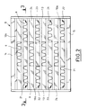
Comme représenté schématiquement à la figure 1, le faisceau de plaques pour échangeur thermique se compose de trois parties, une partie centrale A et deux parties d'extrémités, respectivement B et C.As shown schematically in the figure 1, the bundle of plates for heat exchanger is consists of three parts, a central part A and two end parts, respectively B and C.
La partie centrale A qui constitue la zone de
transfert et d'échange thermique proprement dite se
compose d'un empilement de plaques 10 parallèles les unes
aux autres.The central part A which constitutes the zone of
transfer and heat exchange proper
consists of a stack of
Chaque plaque 10 est constituée d'une tôle
fine, le plus souvent en acier inoxydable, ou tout autre
matériau suffisamment ductile et comporte, de manière
classique, des bords longitudinaux et transversaux à
surface lisse et, entre ces bords, des ondulations 11.Each
Les plaques 10 déterminent entre elles un
double circuit de circulation de deux fluides indépendants.
Les fluides d'échange thermique circulent longitudinalement
d'une extrémité à l'autre du faisceau et
à contre-courant.The
Selon un mode préférentiel de réalisation,
les plaques 10 sont assemblées les unes avec les autres
au niveau de leurs bords longitudinaux par des moyens de
liaison constitués par exemple par des barrettes 12
s'étendant sur toute la longueur des bords longitudinaux
desdites plaques 10 et par une couche de soudure 13
déposée sur toute la longueur et sur toute la hauteur de
chaque surface latérale du faisceau pour former un mur
de soudure étanche.According to a preferred embodiment,
the
L'empilement de plaques 10 est placé entre
une tôle supérieure 14 et une tôle inférieure 15 s'étendant
sur toute la surface des plaques 10 et dont les
pourtours sont reliés aux bords desdites plaques 10 par
les couches de soudure 13.The stack of
Pour diriger les fluides qui circulent à contre-courant dans la partie centrale A d'une extrémité à l'autre du faisceau dans les circuits correspondants, ce faisceau comporte à chacune de ses extrémités, une zone d'entrées et de sorties desdits fluides qui constituent les parties d'extrémités B et C dudit faisceau.To direct the fluids flowing to counter current in the central part A of one end to the other of the beam in the corresponding circuits, this bundle has at each of its ends, a inlet and outlet area of said fluids which constitute the end portions B and C of said bundle.
Comme représentées sur les figures 2 et 3,
ces zones d'entrées et de sorties des fluides sont
formées par un empilement des extrémités planes 10a des
plaques 10 d'échange thermique entre lesquelles sont
insérées des plaques 21 munies de reliefs, ces plaques
10 constituant la zone de transfert et d'échange thermique
entre les fluides.As shown in Figures 2 and 3,
these fluid inlet and outlet areas are
formed by a stack of the
L'ensemble des extrémités planes 10a des
plaques 10 d'échange thermique et des plaques 21 munies
de reliefs déterminent à chaque extrémité du faisceau et
au niveau de chaque circuit de la zone centrale A, au
moins une entrée (a) de l'un des fluides et au moins une
sortie (b) de l'autre desdits fluides.The set of
La répartition des entrées (a) et des sorties (b) à chaque extrémité du faisceau est fonction des caractéristiques des fluides et de l'échange thermique à obtenir entre ces fluides.Distribution of inputs (a) and outputs (b) at each end of the beam is a function of fluid and heat exchange characteristics to get between these fluids.
Selon un exemple de réalisation représenté à la figure 2, les entrées et les sorties comprennent au niveau supérieur du faisceau une entrée (a) pour l'un des fluides, au niveau situé au-dessous, deux sorties (b) pour l'autre desdits fluides et ainsi de suite jusqu'au niveau inférieur de ce faisceau.According to an exemplary embodiment shown in Figure 2, the inputs and outputs include at upper beam level an entry (a) for one of the fluids, at the level below, two outlets (b) for the other of said fluids and so on until lower level of this beam.
Ainsi que représentées aux figures 2 et 3,
les plaques 21 munies de reliefs comportent au niveau de
leurs bords longitudinaux des cales 22 de fixation et
d'écartement avec les extrémités planes 10a des plaques
d'échange thermique 10.As shown in Figures 2 and 3,
the
Chaque bord longitudinal des plaques 21
munies de reliefs est fixé sur une cale 22 par exemple
par un cordon de soudure 23.Each longitudinal edge of the
Chaque ensemble, formé par les extrémités
planes 10a des plaques 10 d'échange thermique, les
plaques 21 munies de reliefs et les cales 22, est
solidarisé de manière étanche avec les bords longitudinaux
des plaques 10 formant la zone A de transfert et
d'échange par les moyens de liaison de ces plaques 10,
c'est-à-dire par les murs de soudure 13.Each set, formed by the
Les portions situées, soit de part et d'autre
des entrées (a), soit entre les sorties (b), sont fermées
par des cales 24, comme représentées aux figures 2 et 3.The portions located on either side
inputs (a), either between outputs (b), are closed
by
D'une manière générale, chaque plaque 21
munie de reliefs comporte au moins une zone de guidage
de l'un des fluides vers le circuit correspondant et une
zone de faible circulation de ce fluide, séparée de la
zone de guidage par au moins une zone de transition
permettant le passage dudit fluide entre ces deux zones.In general, each
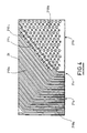
En se rapportant à la figure 4, on va maintenant
décrire un exemple de réalisation d'une plaque 21
munie de reliefs.Referring to Figure 4, we will now
describe an exemplary embodiment of a
Ainsi, la plaque 21 munie de reliefs comporte
une zone 21a de guidage de l'un des fluides vers le
circuit correspondant et une zone 21b de faible circulation
de ce fluide, séparée de la zone 21a de guidage par
au moins une zone 21c de transition permettant le passage
dudit fluide entre ces deux zones 21a et 21b.Thus, the
La zone de guidage 21a de la plaque 21
comporte des ondulations continues 210a qui forment avec
les extrémités planes 10a des plaques 10 d'échange
thermique des canaux de circulation du fluide correspondant
de section constante et orientés vers le circuit
dans lequel circule ce fluide.The
La zone 21b de faible circulation de la
plaque 21 comporte des picots 210b de maintien de l'écartement
avec les extrémités planes 10a des plaques 10
d'échange thermique associées.The low circulation area 21b of the
La zone 21c de transition comporte des
ondulations 210c discontinues longitudinalement formant
des passages 211c entre la zone 21a de guidage et la zone
21b de faible circulation.The
La zone 21c de transition assure le passage
d'une faible quantité de fluide de la zone 21a de guidage
vers la zone 21b de faible circulation de telle sorte que
cette dernière soit baignée par une petite quantité de
fluide et qu'ainsi une totale stagnation de ce fluide
soit évitée dans cette zone.The
Le faisceau de plaques, selon l'invention possède donc, au niveau de chacune de ses extrémités, des zones d'entrées et de sorties formées par les extrémités planes des plaques d'échange thermique entre lesquelles sont insérées des plaques indépendantes et munies de reliefs qui forment des passages de fluides de section constante ce qui permet d'obtenir un écoulement uniforme des fluides améliorant ainsi le rendement du faisceau de plaques.The bundle of plates according to the invention therefore has, at each of its ends, entry and exit zones formed by the ends planes of the heat exchange plates between which independent plates are fitted with reliefs which form cross sectional fluids constant which allows to obtain a uniform flow fluids thus improving the efficiency of the beam plates.
Claims (8)
- Bundle of plates for a heat exchanger, of the type comprising a stack of metal heat exchange plates (10) parallel to one another and each comprising edges with a smooth surface and a central part provided with corrugations (11) to form, with the associated heat exchange plates (10), a double circuit for the circulation of two independent fluids in counter-current, the plates (10) being connected to one another at their longitudinal edges by connecting means (13) and comprising, on the one hand, a zone of heat transfer and exchange between the fluids and, on the other hand, at their free ends, a zone for the entrance and exit of said fluids formed by the flat ends (10a) of the heat exchange plates (10) between which independent plates (21) are inserted which are provided with reliefs to ensure the distribution of fluids in the heat exchange zone, characterised in that each plate (21) provided with reliefs comprises at least one guide zone (21a) for guiding one of the fluids towards the corresponding circuit and one zone (21b) of low circulation of this fluid, which is separated from the guide zone (21a) by at least one transition zone (21c) allowing said fluid to pass between these two zones (21a, 21b).
- Bundle of plates according to claim 1, characterised in that the assembly comprising the ends (10a) of the heat exchange plates and the plates (21) with reliefs determines, at each end of the bundle, a superposition of at least one entrance (a) of one of the fluids and at least one exit (b) of the other end of said fluids.
- Bundle of plates according to claim 1, characterised in that the guide zone (21a) has continuous corrugations (210a).
- Bundle of plates according to claim 3, characterised in that the continuous corrugations (210a) in the guide zone (21a) form, with the ends (10a) of the heat exchange plates (10), fluid circulation channels of constant section oriented towards the corresponding circuits.
- Bundle of plates according to claim 1, characterised in that the low circulation zone (21b) has wedge-shaped portions (210b) for maintaining the spacing between the flat ends (10a) of the associated heat exchange plates (10).
- Bundle of plates according to claim 1, characterised in that the transition zone (21c) comprises discontinuous corrugations (210c) running longitudinally to form passages (211c) between the guide zone (21a) and the low-circulation zone (21b).
- Bundle of plates according to any one of the preceding claims, characterised in that the plates (21) with reliefs comprise, at their longitudinal edges, fixing and spacer wedges (22) with the flat ends (10a) of the heat exchange plates (10).
- Bundle of plates according to claim 7, characterised in that each assembly formed by the flat ends (10a) of the heat exchange plates (10), the plates (21) with reliefs and the wedges (22) is secured in leaktight manner to the longitudinal edges of the plates (10) forming the transfer and exchange zone by the means (13) or connecting these plates (10).
Applications Claiming Priority (2)
| Application Number | Priority Date | Filing Date | Title |
|---|---|---|---|
| FR9414231 | 1994-11-28 | ||
| FR9414231A FR2727505A1 (en) | 1994-11-28 | 1994-11-28 | PLATE HARNESS FOR A HEAT EXCHANGER |
Publications (2)
| Publication Number | Publication Date |
|---|---|
| EP0715144A1 EP0715144A1 (en) | 1996-06-05 |
| EP0715144B1 true EP0715144B1 (en) | 1999-04-07 |
Family
ID=9469211
Family Applications (1)
| Application Number | Title | Priority Date | Filing Date |
|---|---|---|---|
| EP95402548A Expired - Lifetime EP0715144B1 (en) | 1994-11-28 | 1995-11-14 | Stack of plates for a heat exchanger |
Country Status (5)
| Country | Link |
|---|---|
| US (1) | US5584341A (en) |
| EP (1) | EP0715144B1 (en) |
| JP (1) | JP3691136B2 (en) |
| DE (1) | DE69508892T2 (en) |
| FR (1) | FR2727505A1 (en) |
Families Citing this family (18)
| Publication number | Priority date | Publication date | Assignee | Title |
|---|---|---|---|---|
| FR2760656B1 (en) * | 1997-03-17 | 1999-06-04 | Packinox Sa | CATALYTIC PLATE REACTOR |
| US6194609B1 (en) | 1997-06-30 | 2001-02-27 | Bp Amoco Corporation | Crystallization in a plate heat exchanger |
| US5931212A (en) * | 1997-07-15 | 1999-08-03 | Wayne-Dalton Corp. | Motorized operator for doors |
| FR2769082B1 (en) * | 1997-09-29 | 1999-12-24 | Packinox Sa | PLATES OF A HEAT EXCHANGE PLATE BEAM AND METHODS OF MANUFACTURING SUCH A PLATE |
| US6233824B1 (en) | 1999-10-08 | 2001-05-22 | Carrier Corporation | Cylindrical heat exchanger |
| US6408941B1 (en) | 2001-06-29 | 2002-06-25 | Thermal Corp. | Folded fin plate heat-exchanger |
| US6769479B2 (en) * | 2002-06-11 | 2004-08-03 | Solar Turbines Inc | Primary surface recuperator sheet |
| DE10247264A1 (en) * | 2002-10-10 | 2004-04-29 | Behr Gmbh & Co. | Plate heat exchanger in stack construction |
| US6920920B2 (en) * | 2003-04-16 | 2005-07-26 | Catacel Corporation | Heat exchanger |
| US7017655B2 (en) | 2003-12-18 | 2006-03-28 | Modine Manufacturing Co. | Forced fluid heat sink |
| US7159649B2 (en) * | 2004-03-11 | 2007-01-09 | Thermal Corp. | Air-to-air heat exchanger |
| KR100938802B1 (en) * | 2009-06-11 | 2010-01-27 | 국방과학연구소 | Heat exchanger having micro-channels |
| US8375635B2 (en) | 2009-08-26 | 2013-02-19 | Richard Hellinga | Apparatus for opening and closing overhead sectional doors |
| DE102010031561A1 (en) * | 2010-07-20 | 2012-01-26 | Behr Gmbh & Co. Kg | System for using waste heat from an internal combustion engine |
| WO2015086343A1 (en) * | 2013-12-10 | 2015-06-18 | Swep International Ab | Heat exchanger with improved flow |
| EP3150952A1 (en) * | 2015-10-02 | 2017-04-05 | Alfa Laval Corporate AB | Heat transfer plate and plate heat exchanger |
| US10823511B2 (en) * | 2017-06-26 | 2020-11-03 | Raytheon Technologies Corporation | Manufacturing a heat exchanger using a material buildup process |
| EP3473961B1 (en) | 2017-10-20 | 2020-12-02 | Api Heat Transfer, Inc. | Heat exchanger |
Family Cites Families (11)
| Publication number | Priority date | Publication date | Assignee | Title |
|---|---|---|---|---|
| US2875986A (en) * | 1957-04-12 | 1959-03-03 | Ferrotherm Company | Heat exchanger |
| US3282334A (en) * | 1963-04-29 | 1966-11-01 | Trane Co | Heat exchanger |
| US3380517A (en) * | 1966-09-26 | 1968-04-30 | Trane Co | Plate type heat exchangers |
| US3860065A (en) * | 1970-04-08 | 1975-01-14 | Trane Co | Distributor for plate type heat exchanger having side headers |
| US3759323A (en) * | 1971-11-18 | 1973-09-18 | Caterpillar Tractor Co | C-flow stacked plate heat exchanger |
| US4450903A (en) * | 1982-09-20 | 1984-05-29 | The Trane Company | Plate type heat exchanger with transverse hollow slotted bar |
| DE3330254A1 (en) * | 1983-08-22 | 1985-03-14 | Farkas, György, Dipl.-Ing., 3340 Wolfenbüttel | Heat exchanger for ventilation |
| JPS60256792A (en) * | 1984-06-04 | 1985-12-18 | Hitachi Ltd | Lamination type heat exchanger |
| GB8506415D0 (en) * | 1985-03-12 | 1985-04-11 | Atkin H S | Room ventilator |
| US4844151A (en) * | 1986-12-23 | 1989-07-04 | Sundstrand Corporation | Heat exchanger apparatus |
| TW216453B (en) * | 1992-07-08 | 1993-11-21 | Air Prod & Chem | Integrated plate-fin heat exchange reformation |
-
1994
- 1994-11-28 FR FR9414231A patent/FR2727505A1/en active Granted
-
1995
- 1995-11-14 DE DE69508892T patent/DE69508892T2/en not_active Expired - Lifetime
- 1995-11-14 EP EP95402548A patent/EP0715144B1/en not_active Expired - Lifetime
- 1995-11-22 JP JP30477195A patent/JP3691136B2/en not_active Expired - Lifetime
- 1995-11-28 US US08/563,469 patent/US5584341A/en not_active Expired - Lifetime
Also Published As
| Publication number | Publication date |
|---|---|
| DE69508892D1 (en) | 1999-05-12 |
| US5584341A (en) | 1996-12-17 |
| FR2727505B1 (en) | 1997-02-14 |
| FR2727505A1 (en) | 1996-05-31 |
| JPH08219677A (en) | 1996-08-30 |
| EP0715144A1 (en) | 1996-06-05 |
| DE69508892T2 (en) | 1999-08-12 |
| JP3691136B2 (en) | 2005-08-31 |
Similar Documents
| Publication | Publication Date | Title |
|---|---|---|
| EP0715144B1 (en) | Stack of plates for a heat exchanger | |
| EP0186592B1 (en) | Plate heat exchanger | |
| EP0740949A1 (en) | Plate type exchanger | |
| EP1012522B1 (en) | Heat exchanger, and heat exchanging beam, and related welding methods and production | |
| EP0571263B1 (en) | Stack of plates for a heat-exchanger and method of assembling same | |
| KR100217515B1 (en) | Laminated heat exchanger tube and manufactuing method therefor | |
| EP2856060B1 (en) | Plate heat exchanger for homogeneous fluid flows between ducts | |
| FR2824895A1 (en) | Undulating louver fin for plate heat exchanger comprises set of undulating legs connected alternately by undulating top and undulating base and provided with inclined flaps cut in legs | |
| EP1426722A1 (en) | Plate for heat exchanger and plate heat exchanger | |
| EP0706634B1 (en) | Welded plate heat exchanger and method for welding heat transfer plates to a plate heat exchanger | |
| FR2862747A1 (en) | HEAT EXCHANGER PLATE, AND THIS EXCHANGER | |
| JP2004516448A (en) | Finned tube block heat exchanger with grooved spacer bar | |
| JPS61122493A (en) | Plate type heat exchanger | |
| WO1999017070A1 (en) | Plates of an array of heat transfer plates | |
| EP0553340B1 (en) | Plate-type heat exchanger | |
| FR2793875A1 (en) | Plate heat exchanger has enclosed elongate bundle of plates open at one end within closed elongate drum with free space around enclosed bundle | |
| FR2814537A1 (en) | Heat exchanger for cooling vehicle exhaust has longitudinal partitions connected to collector boxes at each end and transverse partitions, some of which are connected to collector boxes on each side, ensuring fluid flows in one direction | |
| FR2738906A1 (en) | BEAM OF PLATES FOR A HEAT EXCHANGER AND HEAT EXCHANGER COMPRISING SUCH A BEAM OF PLATES | |
| WO2015004359A1 (en) | Heat exchange device and method for making such a device | |
| EP0865818B1 (en) | Plate-type reactor for catalytic reaction | |
| FR2764973A1 (en) | METHOD FOR ASSEMBLING THE PLATES OF A BEAM OF PLATES AND BEAM OF PLATES MADE BY SUCH A METHOD | |
| WO2000028270A1 (en) | Plate heat exchanger | |
| FR2716960A1 (en) | Heat exchanger plate assembly | |
| BE894761A (en) | Plate type heat exchanger - has one plate with patterned spacer protrusions to one side of collector channels | |
| BE357823A (en) |
Legal Events
| Date | Code | Title | Description |
|---|---|---|---|
| PUAI | Public reference made under article 153(3) epc to a published international application that has entered the european phase |
Free format text: ORIGINAL CODE: 0009012 |
|
| AK | Designated contracting states |
Kind code of ref document: A1 Designated state(s): BE DE ES FR GB IT NL |
|
| 17P | Request for examination filed |
Effective date: 19961126 |
|
| 17Q | First examination report despatched |
Effective date: 19980306 |
|
| GRAG | Despatch of communication of intention to grant |
Free format text: ORIGINAL CODE: EPIDOS AGRA |
|
| GRAG | Despatch of communication of intention to grant |
Free format text: ORIGINAL CODE: EPIDOS AGRA |
|
| GRAH | Despatch of communication of intention to grant a patent |
Free format text: ORIGINAL CODE: EPIDOS IGRA |
|
| GRAH | Despatch of communication of intention to grant a patent |
Free format text: ORIGINAL CODE: EPIDOS IGRA |
|
| GRAA | (expected) grant |
Free format text: ORIGINAL CODE: 0009210 |
|
| AK | Designated contracting states |
Kind code of ref document: B1 Designated state(s): BE DE ES FR GB IT NL |
|
| PG25 | Lapsed in a contracting state [announced via postgrant information from national office to epo] |
Ref country code: IT Free format text: LAPSE BECAUSE OF FAILURE TO SUBMIT A TRANSLATION OF THE DESCRIPTION OR TO PAY THE FEE WITHIN THE PRESCRIBED TIME-LIMIT;WARNING: LAPSES OF ITALIAN PATENTS WITH EFFECTIVE DATE BEFORE 2007 MAY HAVE OCCURRED AT ANY TIME BEFORE 2007. THE CORRECT EFFECTIVE DATE MAY BE DIFFERENT FROM THE ONE RECORDED. Effective date: 19990407 Ref country code: ES Free format text: THE PATENT HAS BEEN ANNULLED BY A DECISION OF A NATIONAL AUTHORITY Effective date: 19990407 |
|
| 111L | Licence recorded |
Free format text: 981021 0100 ZIEPACK, SOCIETE ANONYME |
|
| REF | Corresponds to: |
Ref document number: 69508892 Country of ref document: DE Date of ref document: 19990512 |
|
| GBT | Gb: translation of ep patent filed (gb section 77(6)(a)/1977) |
Effective date: 19990709 |
|
| PG25 | Lapsed in a contracting state [announced via postgrant information from national office to epo] |
Ref country code: BE Free format text: LAPSE BECAUSE OF NON-PAYMENT OF DUE FEES Effective date: 19991130 |
|
| PLBE | No opposition filed within time limit |
Free format text: ORIGINAL CODE: 0009261 |
|
| STAA | Information on the status of an ep patent application or granted ep patent |
Free format text: STATUS: NO OPPOSITION FILED WITHIN TIME LIMIT |
|
| 26N | No opposition filed | ||
| BERE | Be: lapsed |
Owner name: PACKINOX Effective date: 19991130 |
|
| REG | Reference to a national code |
Ref country code: GB Ref legal event code: IF02 |
|
| PGFP | Annual fee paid to national office [announced via postgrant information from national office to epo] |
Ref country code: GB Payment date: 20141118 Year of fee payment: 20 Ref country code: DE Payment date: 20141113 Year of fee payment: 20 Ref country code: FR Payment date: 20141125 Year of fee payment: 20 |
|
| PGFP | Annual fee paid to national office [announced via postgrant information from national office to epo] |
Ref country code: NL Payment date: 20141024 Year of fee payment: 20 |
|
| REG | Reference to a national code |
Ref country code: DE Ref legal event code: R071 Ref document number: 69508892 Country of ref document: DE |
|
| REG | Reference to a national code |
Ref country code: NL Ref legal event code: MK Effective date: 20151113 |
|
| REG | Reference to a national code |
Ref country code: GB Ref legal event code: PE20 Expiry date: 20151113 |
|
| PG25 | Lapsed in a contracting state [announced via postgrant information from national office to epo] |
Ref country code: GB Free format text: LAPSE BECAUSE OF EXPIRATION OF PROTECTION Effective date: 20151113 |