EP0713748B2 - Linear Actuator - Google Patents
Linear Actuator Download PDFInfo
- Publication number
- EP0713748B2 EP0713748B2 EP95117908A EP95117908A EP0713748B2 EP 0713748 B2 EP0713748 B2 EP 0713748B2 EP 95117908 A EP95117908 A EP 95117908A EP 95117908 A EP95117908 A EP 95117908A EP 0713748 B2 EP0713748 B2 EP 0713748B2
- Authority
- EP
- European Patent Office
- Prior art keywords
- slide table
- cylinder body
- hole
- linear actuator
- guide
- Prior art date
- Legal status (The legal status is an assumption and is not a legal conclusion. Google has not performed a legal analysis and makes no representation as to the accuracy of the status listed.)
- Expired - Lifetime
Links
Images

Classifications
-
- F—MECHANICAL ENGINEERING; LIGHTING; HEATING; WEAPONS; BLASTING
- F15—FLUID-PRESSURE ACTUATORS; HYDRAULICS OR PNEUMATICS IN GENERAL
- F15B—SYSTEMS ACTING BY MEANS OF FLUIDS IN GENERAL; FLUID-PRESSURE ACTUATORS, e.g. SERVOMOTORS; DETAILS OF FLUID-PRESSURE SYSTEMS, NOT OTHERWISE PROVIDED FOR
- F15B9/00—Servomotors with follow-up action, e.g. obtained by feed-back control, i.e. in which the position of the actuated member conforms with that of the controlling member
- F15B9/02—Servomotors with follow-up action, e.g. obtained by feed-back control, i.e. in which the position of the actuated member conforms with that of the controlling member with servomotors of the reciprocatable or oscillatable type
-
- B—PERFORMING OPERATIONS; TRANSPORTING
- B23—MACHINE TOOLS; METAL-WORKING NOT OTHERWISE PROVIDED FOR
- B23Q—DETAILS, COMPONENTS, OR ACCESSORIES FOR MACHINE TOOLS, e.g. ARRANGEMENTS FOR COPYING OR CONTROLLING; MACHINE TOOLS IN GENERAL CHARACTERISED BY THE CONSTRUCTION OF PARTICULAR DETAILS OR COMPONENTS; COMBINATIONS OR ASSOCIATIONS OF METAL-WORKING MACHINES, NOT DIRECTED TO A PARTICULAR RESULT
- B23Q1/00—Members which are comprised in the general build-up of a form of machine, particularly relatively large fixed members
- B23Q1/25—Movable or adjustable work or tool supports
- B23Q1/44—Movable or adjustable work or tool supports using particular mechanisms
- B23Q1/56—Movable or adjustable work or tool supports using particular mechanisms with sliding pairs only, the sliding pairs being the first two elements of the mechanism
- B23Q1/58—Movable or adjustable work or tool supports using particular mechanisms with sliding pairs only, the sliding pairs being the first two elements of the mechanism a single sliding pair
-
- B—PERFORMING OPERATIONS; TRANSPORTING
- B23—MACHINE TOOLS; METAL-WORKING NOT OTHERWISE PROVIDED FOR
- B23Q—DETAILS, COMPONENTS, OR ACCESSORIES FOR MACHINE TOOLS, e.g. ARRANGEMENTS FOR COPYING OR CONTROLLING; MACHINE TOOLS IN GENERAL CHARACTERISED BY THE CONSTRUCTION OF PARTICULAR DETAILS OR COMPONENTS; COMBINATIONS OR ASSOCIATIONS OF METAL-WORKING MACHINES, NOT DIRECTED TO A PARTICULAR RESULT
- B23Q5/00—Driving or feeding mechanisms; Control arrangements therefor
- B23Q5/22—Feeding members carrying tools or work
- B23Q5/26—Fluid-pressure drives
-
- F—MECHANICAL ENGINEERING; LIGHTING; HEATING; WEAPONS; BLASTING
- F15—FLUID-PRESSURE ACTUATORS; HYDRAULICS OR PNEUMATICS IN GENERAL
- F15B—SYSTEMS ACTING BY MEANS OF FLUIDS IN GENERAL; FLUID-PRESSURE ACTUATORS, e.g. SERVOMOTORS; DETAILS OF FLUID-PRESSURE SYSTEMS, NOT OTHERWISE PROVIDED FOR
- F15B15/00—Fluid-actuated devices for displacing a member from one position to another; Gearing associated therewith
- F15B15/08—Characterised by the construction of the motor unit
- F15B15/082—Characterised by the construction of the motor unit the motor being of the slotted cylinder type
-
- F—MECHANICAL ENGINEERING; LIGHTING; HEATING; WEAPONS; BLASTING
- F15—FLUID-PRESSURE ACTUATORS; HYDRAULICS OR PNEUMATICS IN GENERAL
- F15B—SYSTEMS ACTING BY MEANS OF FLUIDS IN GENERAL; FLUID-PRESSURE ACTUATORS, e.g. SERVOMOTORS; DETAILS OF FLUID-PRESSURE SYSTEMS, NOT OTHERWISE PROVIDED FOR
- F15B15/00—Fluid-actuated devices for displacing a member from one position to another; Gearing associated therewith
- F15B15/08—Characterised by the construction of the motor unit
- F15B15/14—Characterised by the construction of the motor unit of the straight-cylinder type
Definitions
- the present invention relates to a linear actuator according to the preamble of claim 1.
- Linear actuators have heretofore been used as means for conveying workpieces or the like.
- Linear actuators are capable of linearly reciprocally moving a movable table along a cylinder body for thereby conveying a workpiece placed on the movable table.
- a linear actuator according to the preamble of claim 1 is known from US patent 4 991 494.
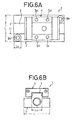
- FIGS. 6A and 6B of the accompanying drawings illustrate the disclosed linear actuator in the form of a fluid pressure cylinder assembly.
- the fluid pressure cylinder assembly generally designated by the reference numeral 1, comprises a cylinder body 2, a guide rail 3 projecting upwardly from and extending longitudinally on an upper surface of the cylinder body 2, and a slide table 4 mounted on the guide rail 3 for sliding displacement therealong in response to displacement of a piston disposed in a cylinder chamber which is defined in the cylinder body 2.
- the slide table 4 has a ball circulation hole (not shown) defined longitudinally therein and accommodating a plurality of balls for rolling movement therein.
- the slide table 4 also has a plurality of screw holes 5a ⁇ 5d that are defined in an upper surface thereof for attachment of a workpiece to be conveyed by the fluid pressure cylinder assembly 1.
- the cylinder body 2 has a pair of attachment holes 6a, 6b defined in respective diagonally opposite corners thereof for installing the cylinder body 2 on another member (not shown).
- the cylinder body 2 has a transverse width L represented by L ⁇ L 1 + (L 2 ⁇ 2) where L 1 is the width of the guide rail 3 and L 2 is the diameter of each of the attachment holes 6a, 6b. Therefore, the transverse width L is substantially equal to the sum of the width L 1 of the guide rail 3 and the diameters L 2 of the attachment holes 6a, 6b.
- the width L 1 of the guide rail 3 cannot be reduced because the rigidity of the slide table 4 would be lowered if width L 1 were reduced.
- the transverse width L is required to be substantially equal to the sum of the width L 1 of the guide rail 3 and the diameters L 2 of the attachment holes 6a, 6b so that the cylinder body 2 maintains a desired level of rigidity.
- a process of machining a slide table blank into the slide table 4 is complex because the ball circulation hole needs to be defined longitudinally in the slide table blank and the screw holes 5a - 5d need to be defined in the slide table in a direction different from the direction of the ball circuit hole.
- Document EP 0 536 799 A discloses a rodless cylinder having a conventional sealing member disposed centrally along the main body.
- the slide table comprises downwardly extending load transmitting means received in respective grooves on the upper face of the cylinder body and sliding along guide rails provided in these growes.
- the slide table and the pistons which reciprocally move along the cylinder body are united with each other by way of a coupling part which projects through a slit formed in a longitudinal direction of the cylinder body.
- the grooves receiving the load transmitting means of the slide table are provided on both sides parallel to the slit. While preventing that upon the application of a lateral load the slit is narrowed and the piston is suddenly stopped, this is a rather complicated structure.
- the linear actuator includes a slide table that can be machined with ease.
- the slide table further can be replaced with a variety of different slide tables.
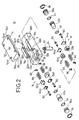
- FIG. 1 shows in perspective a linear actuator 10 according to the present invention.
- the linear actuator 10 basically comprises a cylinder body 12, a slide table 14 mounted on the cylinder body 12 for linear reciprocating movement in longitudinal directions of the cylinder body 12, and a pair of slide mechanisms 16 (see FIG. 2) for reciprocally moving the slide table 14 smoothly in the longitudinal directions of the cylinder body 12.
- the cylinder body 12 has a pair of integral guide blocks (second guide means) 18a, 18b disposed on an upper surface thereof in transversely spaced confronting relation to each other.
- the guide blocks 18a, 18b have respective ball circulation holes 20a, 20b and respective ball rolling grooves 22a, 22b defined therein in the longitudinal direction of the cylinder body 12 in spaced relation to the ball circulation holes 20a, 20b.
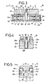
- the cylinder body 12 has a pair of substantially elliptical slots 26a, 26b (see FIG. 3) defined substantially centrally in respective upper and lower surfaces thereof for allowing a substantially cylindrical joint 24 (described later on) to be displaced freely therein.
- the cylinder body 12 also has a pair of attachment holes 30a, 30b defined in its upper surface at respective steps 28 in diagonally opposite corners thereof for installing the cylinder body 2 on another member (not shown) with bolts (not shown) inserted through the attachment holes 30a, 30b.
- the cylinder body 12 further has a through hole 32 (see FIGS. 2 and 3) defined longitudinally therein and communicating with the slots 26a, 26b.
- the opposite ends of the through hole 32 are closed by respective end caps 36a, 36b with respective seal rings 34 mounted thereon.
- the end caps 36a, 36b are hermetically retained in the opposite ends of the through hole 32 by respective retaining rings 38.
- the through hole 32 accommodates therein a pair of pistons 42a, 42b disposed for sliding displacement along an inner wall surface of the through hole 32.
- Seal rings 40 are mounted respectively on outer circumferential surfaces of the pistons 42a, 42b.
- the end caps 36a, 36b and the piston 42a, 42b jointly define respective cylinder chambers 44a, 44b in the through hole 32.
- the cylinder chambers 44a, 44b are held in communication with fluid outlet/inlet ports 48a, 48b (see FIGS. 1 and 5) defined in one side of the cylinder body 12, through respective fixed restrictions 46.
- the substantially cylindrical joint 24 which extends substantially vertically is positioned between the pistons 42a, 42b, and has an externally threaded upper end threaded in a threaded hole 50 (see FIGS. 2 and 3) defined substantially centrally in the slide table 14.
- the joint 24 includes a spigot portion 52 immediately below the externally threaded upper end.
- the spigot portion 52 is securely fitted in an annular step which is defined in the slide table 14 beneath the threaded hole 50, so that the joint 24 is firmly fixed to the slide table 14.
- the slide table 14 has a plurality of attachment holes 54a ⁇ 54d defined therein at respective four corners thereof.
- the slide table 14 also has a guide (first guide means) 56 integrally projecting upwardly from and extending longitudinally on a lower surface of the slide table 14.
- the guide 56 has a pair of ball rolling grooves 58a, 58b (see also FIG. 5) defined in respective transverse opposite sides thereof and extending in the longitudinal direction thereof.
- the slide mechanisms 16 are positioned respectively on longitudinal opposite ends of the guide blocks 18a, 18b.
- Each of the slide mechanisms 16, which are identical in structure to each other, comprises two pairs of covers 62a, 62b and two pairs of scrapers 64a, 64b which are mounted on respective longitudinally opposite ends of the guide blocks 18a, 18b by screws 60.
- the ball circulation holes 20a, 20b defined in the respective guide blocks 18a, 18b extend in the longitudinal direction thereof, and the ball rolling grooves 22a, 22b defined in the respective guide blocks 18a, 18b extend along confronting inner wall surfaces thereof in the longitudinal direction thereof.
- the slide mechanism 16 also has two pairs of return guides 66 mounted respectively on the longitudinally opposite ends of the guide blocks 18a, 18b and interconnecting the ball circulation holes 20a, 20b and the ball rolling grooves 22a, 22b, and two sets of balls (rolling elements) 68 placed in the ball circulation holes 20a, 20b and the ball rolling grooves 22a, 22b for rolling movement therealong.
- the covers 62a, 62b have respective recesses 70b, 70a defined therein which interconnect the ball circulation holes 20a, 20b and the ball rolling grooves 22a, 22b.
- the ball circulation holes 20a, 20b, the ball rolling grooves 22a, 22b, the return guides 66, and the recesses 70b, 70a jointly serve as endless circulatory tracks for the balls 68 to rolling move therealong.
- a fluid supplied under pressure from a fluid pressure supply (not shown) is introduced into the fluid outlet/inlet port 48b by a directional control valve (not shown). At this time, the other fluid outlet/inlet port 48a is vented to the atmosphere by the directional control valve.
- the introduced fluid is supplied through the fixed restriction 46 connected to the fluid outlet/inlet port 48b into the cylinder chamber 44b, displacing the piston 42b in the direction indicated by the arrow X 1 .
- the piston 42b is displaced until an end thereof abuts against the joint 24 as indicated by the broken lines in FIG. 3.
- the slide table 14 coupled to the joint 24 is displaced in unison with the joint 24 in the direction indicated by the arrow X 1 .
- the slide table 14 reaches an end of its stroke when the joint 24 engages respective inner end surfaces of the slots 26a, 26b.
- a fluid under pressure is introduced into the fluid outlet/inlet port 48a by the directional control valve.
- the introduced fluid is supplied through the fixed restriction 46 connected to the fluid outlet/inlet port 48a into the cylinder chamber 44a, displacing the piston 42a in the direction indicated by the arrow X 2 .
- the piston 42a pushes the joint 24 along the slots 26a, 26b in the direction indicated by the arrow X 2 , thereby displacing the slide table 14 also in the direction indicated by the arrow X 2 .
- the slide table 14 reaches an opposite end of its stroke when the joint 24 engages respective opposite inner end surfaces of the slots 26a, 26b.
- the guide 56 integrally projects upwardly from and extends longitudinally on the lower surface of the slide table 14, and the guide blocks 18a, 18b which guide the guide 56 through the balls 68 for sliding movement in the longitudinal direction of the cylinder body 12 are integrally formed with the cylinder body 12.
- the attachment holes 30a, 30b can be defined in the cylinder body 12 at desired positions thereon without being affected by the transverse width H 1 (see FIG. 5) of the cylinder body 12, which is not the case with the conventional linear actuator shown in FIGS. 6A and 6B. Consequently, the cylinder body 12 of the linear actuator 10 according to the present invention can reduce its transverse width H (see FIG. 5), with the result that the linear actuator 10 can be reduced in size and weight.
- the attachment holes 54a ⁇ 54d are oriented in one direction with respect to the slide table 14. Since the slide table 14 does not have various holes defined in different directions, the slide table 14 can be machined relatively easily from a slide table blank.
- the guide 56 which is guided by the guide blocks 18a, 18b simply projects downwardly from the lower surface of the guide table 14. Therefore, the slide table 14 can be replaced with a variety of different slide tables insofar as they have guides identical to the guide 56.
Applications Claiming Priority (3)
| Application Number | Priority Date | Filing Date | Title |
|---|---|---|---|
| JP29011294A JP3896550B2 (ja) | 1994-11-24 | 1994-11-24 | リニアアクチュエータ |
| JP290112/94 | 1994-11-24 | ||
| JP29011294 | 1994-11-24 |
Publications (3)
| Publication Number | Publication Date |
|---|---|
| EP0713748A1 EP0713748A1 (en) | 1996-05-29 |
| EP0713748B1 EP0713748B1 (en) | 2000-05-24 |
| EP0713748B2 true EP0713748B2 (en) | 2003-07-09 |
Family
ID=17751960
Family Applications (1)
| Application Number | Title | Priority Date | Filing Date |
|---|---|---|---|
| EP95117908A Expired - Lifetime EP0713748B2 (en) | 1994-11-24 | 1995-11-14 | Linear Actuator |
Country Status (7)
| Country | Link |
|---|---|
| US (1) | US5606902A (ko) |
| EP (1) | EP0713748B2 (ko) |
| JP (1) | JP3896550B2 (ko) |
| KR (1) | KR0180961B1 (ko) |
| CN (1) | CN1072327C (ko) |
| DE (1) | DE69517135T3 (ko) |
| TW (1) | TW320675B (ko) |
Families Citing this family (24)
| Publication number | Priority date | Publication date | Assignee | Title |
|---|---|---|---|---|
| GB2316132B (en) * | 1996-08-13 | 1999-02-17 | Smc Kk | Linear actuator |
| US5868499A (en) * | 1996-09-06 | 1999-02-09 | Deutsche Star Gmbh | Linear guiding unit |
| DE29817441U1 (de) | 1998-09-30 | 1998-12-10 | Festo Ag & Co | Linearantrieb |
| JP3459386B2 (ja) * | 1999-10-15 | 2003-10-20 | Smc株式会社 | 可逆式取付機構を有する流体圧機器 |
| USRE47599E1 (en) | 2000-10-20 | 2019-09-10 | Promega Corporation | RF point of sale and delivery method and system using communication with remote computer and having features to read a large number of RF tags |
| WO2002035432A1 (en) * | 2000-10-20 | 2002-05-02 | Promega Corporation | Radio frequency identification method and system of distributing products |
| US20020183882A1 (en) * | 2000-10-20 | 2002-12-05 | Michael Dearing | RF point of sale and delivery method and system using communication with remote computer and having features to read a large number of RF tags |
| US6756707B2 (en) * | 2001-01-26 | 2004-06-29 | Tol-O-Matic, Inc. | Electric actuator |
| JP2003222104A (ja) * | 2002-01-31 | 2003-08-08 | Smc Corp | リニアアクチュエータ |
| US7351288B2 (en) * | 2003-12-22 | 2008-04-01 | Asml Holding N.V. | Shock absorbing fluidic actuator |
| US7541707B2 (en) * | 2004-01-08 | 2009-06-02 | Tol-O-Matic, Inc. | Electric actuator |
| DE502004000628D1 (de) | 2004-03-01 | 2006-06-29 | Festo Ag & Co | Linearantrieb mit einem von zwei Führungseinheiten flankierten Schlitten |
| JP4587105B2 (ja) * | 2005-05-18 | 2010-11-24 | Smc株式会社 | リニアアクチュエータ及びその加工方法 |
| US7710275B2 (en) | 2007-03-16 | 2010-05-04 | Promega Corporation | RFID reader enclosure and man-o-war RFID reader system |
| US8196484B2 (en) * | 2008-04-18 | 2012-06-12 | Tol-O-Matic, Inc. | Electric actuator |
| CN101737373B (zh) * | 2008-11-07 | 2012-07-04 | 沈阳芯源微电子设备有限公司 | 气缸和导轨的保护缓冲结构 |
| US9431868B2 (en) * | 2010-01-19 | 2016-08-30 | Tolomatic, Inc. | Manual override device for an electric actuator and method for use |
| US8701513B2 (en) | 2010-07-14 | 2014-04-22 | Tol-O-Matic, Inc. | Screw driven linear actuator and housing assembly |
| CN102294840A (zh) * | 2011-08-12 | 2011-12-28 | 成都科盛石油科技有限公司 | 压力机滑台 |
| CN102862061B (zh) * | 2012-09-14 | 2014-06-25 | 扬州市组合机床厂 | 组合机床中具有多级定位装置的液压滑台 |
| CN102878148B (zh) * | 2012-09-29 | 2015-05-06 | 江苏昌力油缸有限公司 | 防偏转多级油缸 |
| RU2679292C2 (ru) * | 2014-07-09 | 2019-02-06 | СМСи КОРПОРЕЙШН | Направляющий механизм для цилиндра и цилиндр с направляющим механизмом |
| CN106938764B (zh) * | 2017-04-28 | 2022-12-27 | 浙江硕和机器人科技股份有限公司 | 一种导板往复输送机构 |
| EP3712443A1 (en) * | 2019-03-22 | 2020-09-23 | Comercial de Utiles y Moldes, S.A. | Hydraulic cylinder |
Citations (1)
| Publication number | Priority date | Publication date | Assignee | Title |
|---|---|---|---|---|
| US4991494A (en) † | 1988-06-08 | 1991-02-12 | Univer S.P.A. | Sealing device for rodless pneumatic cylinders |
Family Cites Families (14)
| Publication number | Priority date | Publication date | Assignee | Title |
|---|---|---|---|---|
| US4401011A (en) * | 1980-05-28 | 1983-08-30 | Wallberg Kurt Ake | Method to adjust and/or indicate a liquid or gaseous pressure, and a device for utilization of the method |
| US4403389A (en) * | 1981-02-05 | 1983-09-13 | Stevens Engineering, Inc. | Slide mechanism |
| US4664020A (en) * | 1981-06-25 | 1987-05-12 | Proma Produkt-Und Marketing Gesellschaft M.B.H. | Piston-cylinder structure |
| JPS59214537A (ja) * | 1983-05-21 | 1984-12-04 | Sanruutsu Kk | 往復台摺動装置 |
| JPS6085840A (ja) * | 1983-10-15 | 1985-05-15 | Shinkawa Ltd | 可動テ−ブルの支持移動装置 |
| JPS61293740A (ja) * | 1985-06-21 | 1986-12-24 | Hiroshi Teramachi | テ−ブル移送装置 |
| US4838147A (en) * | 1988-01-26 | 1989-06-13 | Grigory Grishchenko | Pressure fluid actuator |
| JPH0542716A (ja) * | 1990-11-07 | 1993-02-23 | Canon Inc | 光ビームを用いた画像形成装置 |
| DE59106274D1 (de) * | 1991-05-29 | 1995-09-21 | Hygrama Ag | Linearantrieb. |
| JP2607486Y2 (ja) | 1991-09-25 | 2001-09-04 | エヌオーケー株式会社 | 流体圧シリンダ |
| US5275088A (en) * | 1991-10-11 | 1994-01-04 | Smc Kabushiki Kaisha | Rodless cylinder |
| JPH0667046A (ja) * | 1992-08-21 | 1994-03-11 | Sharp Corp | 光集積回路 |
| US5363741A (en) * | 1992-12-24 | 1994-11-15 | Smc Kabushiki Kaisha | Slide actuator |
| US5303638A (en) * | 1993-02-26 | 1994-04-19 | Green Joseph H | Rodless piston and cylinder assembly for a reciprocating carriage |
-
1994
- 1994-11-24 JP JP29011294A patent/JP3896550B2/ja not_active Expired - Fee Related
-
1995
- 1995-11-14 EP EP95117908A patent/EP0713748B2/en not_active Expired - Lifetime
- 1995-11-14 DE DE69517135T patent/DE69517135T3/de not_active Expired - Lifetime
- 1995-11-15 US US08/559,452 patent/US5606902A/en not_active Expired - Lifetime
- 1995-11-23 CN CN95119771A patent/CN1072327C/zh not_active Expired - Lifetime
- 1995-11-24 KR KR1019950043471A patent/KR0180961B1/ko not_active IP Right Cessation
- 1995-11-29 TW TW084112691A patent/TW320675B/zh not_active IP Right Cessation
Patent Citations (1)
| Publication number | Priority date | Publication date | Assignee | Title |
|---|---|---|---|---|
| US4991494A (en) † | 1988-06-08 | 1991-02-12 | Univer S.P.A. | Sealing device for rodless pneumatic cylinders |
Also Published As
| Publication number | Publication date |
|---|---|
| KR960018264A (ko) | 1996-06-17 |
| TW320675B (ko) | 1997-11-21 |
| CN1132829A (zh) | 1996-10-09 |
| JPH08145011A (ja) | 1996-06-04 |
| JP3896550B2 (ja) | 2007-03-22 |
| KR0180961B1 (ko) | 1999-04-15 |
| DE69517135T2 (de) | 2001-02-01 |
| EP0713748B1 (en) | 2000-05-24 |
| DE69517135T3 (de) | 2004-05-06 |
| EP0713748A1 (en) | 1996-05-29 |
| US5606902A (en) | 1997-03-04 |
| CN1072327C (zh) | 2001-10-03 |
| DE69517135D1 (de) | 2000-06-29 |
Similar Documents
| Publication | Publication Date | Title |
|---|---|---|
| EP0713748B2 (en) | Linear Actuator | |
| EP0704275B1 (en) | Linear actuator | |
| EP0603459B1 (en) | Slide actuator | |
| KR100235217B1 (ko) | 선형 액츄에이터 | |
| CA1172132A (en) | Variable gain servo controlled directional valve | |
| GB2180303A (en) | A linear rolling bearing unit | |
| US5044780A (en) | Linear sliding bearing and linear sliding table | |
| EP0382096B1 (en) | Hydrostatically supporting device for slide | |
| KR950009978B1 (ko) | 로드리스 실린더 | |
| US5038671A (en) | Control valve | |
| US5347914A (en) | Traverse apparatus | |
| JPH1061611A (ja) | リニアアクチュエータ | |
| KR20100011200A (ko) | 공기부상형 저마찰 고속 시일리스 실린더 | |
| EP0711928B1 (en) | Rodless cylinder | |
| EP0472887B1 (de) | Ventil | |
| JP2607486Y2 (ja) | 流体圧シリンダ | |
| USRE34621E (en) | Self equalizing piercing machine | |
| US5485864A (en) | Pressure compensation valve | |
| US6685178B2 (en) | Linear guiding apparatus for machine tool | |
| CN214988591U (zh) | 夹具及传输系统 | |
| RU2096225C1 (ru) | Гидроруль транспортного средства | |
| KR19980053810U (ko) | 고강성 유정압 슬라이드를 이용한 테이블 이송장치 | |
| DD209134B1 (de) | Hydraulisch-pneumatische vorschubeinrichtung |
Legal Events
| Date | Code | Title | Description |
|---|---|---|---|
| PUAI | Public reference made under article 153(3) epc to a published international application that has entered the european phase |
Free format text: ORIGINAL CODE: 0009012 |
|
| 17P | Request for examination filed |
Effective date: 19951123 |
|
| AK | Designated contracting states |
Kind code of ref document: A1 Designated state(s): DE FR GB |
|
| 17Q | First examination report despatched |
Effective date: 19970214 |
|
| GRAG | Despatch of communication of intention to grant |
Free format text: ORIGINAL CODE: EPIDOS AGRA |
|
| GRAG | Despatch of communication of intention to grant |
Free format text: ORIGINAL CODE: EPIDOS AGRA |
|
| GRAH | Despatch of communication of intention to grant a patent |
Free format text: ORIGINAL CODE: EPIDOS IGRA |
|
| GRAH | Despatch of communication of intention to grant a patent |
Free format text: ORIGINAL CODE: EPIDOS IGRA |
|
| GRAA | (expected) grant |
Free format text: ORIGINAL CODE: 0009210 |
|
| AK | Designated contracting states |
Kind code of ref document: B1 Designated state(s): DE FR GB |
|
| REF | Corresponds to: |
Ref document number: 69517135 Country of ref document: DE Date of ref document: 20000629 |
|
| ET | Fr: translation filed | ||
| PLBQ | Unpublished change to opponent data |
Free format text: ORIGINAL CODE: EPIDOS OPPO |
|
| PLBI | Opposition filed |
Free format text: ORIGINAL CODE: 0009260 |
|
| 26 | Opposition filed |
Opponent name: FESTO AG & CO Effective date: 20010124 |
|
| PLBF | Reply of patent proprietor to notice(s) of opposition |
Free format text: ORIGINAL CODE: EPIDOS OBSO |
|
| PLBF | Reply of patent proprietor to notice(s) of opposition |
Free format text: ORIGINAL CODE: EPIDOS OBSO |
|
| PLBF | Reply of patent proprietor to notice(s) of opposition |
Free format text: ORIGINAL CODE: EPIDOS OBSO |
|
| REG | Reference to a national code |
Ref country code: GB Ref legal event code: IF02 |
|
| PLAW | Interlocutory decision in opposition |
Free format text: ORIGINAL CODE: EPIDOS IDOP |
|
| PLAW | Interlocutory decision in opposition |
Free format text: ORIGINAL CODE: EPIDOS IDOP |
|
| PUAH | Patent maintained in amended form |
Free format text: ORIGINAL CODE: 0009272 |
|
| STAA | Information on the status of an ep patent application or granted ep patent |
Free format text: STATUS: PATENT MAINTAINED AS AMENDED |
|
| 27A | Patent maintained in amended form |
Effective date: 20030709 |
|
| AK | Designated contracting states |
Designated state(s): DE FR GB |
|
| ET3 | Fr: translation filed ** decision concerning opposition | ||
| PGFP | Annual fee paid to national office [announced via postgrant information from national office to epo] |
Ref country code: FR Payment date: 20081113 Year of fee payment: 14 |
|
| PGFP | Annual fee paid to national office [announced via postgrant information from national office to epo] |
Ref country code: GB Payment date: 20081117 Year of fee payment: 14 |
|
| GBPC | Gb: european patent ceased through non-payment of renewal fee |
Effective date: 20091114 |
|
| REG | Reference to a national code |
Ref country code: FR Ref legal event code: ST Effective date: 20100730 |
|
| PG25 | Lapsed in a contracting state [announced via postgrant information from national office to epo] |
Ref country code: FR Free format text: LAPSE BECAUSE OF NON-PAYMENT OF DUE FEES Effective date: 20091130 |
|
| PG25 | Lapsed in a contracting state [announced via postgrant information from national office to epo] |
Ref country code: GB Free format text: LAPSE BECAUSE OF NON-PAYMENT OF DUE FEES Effective date: 20091114 |
|
| PGFP | Annual fee paid to national office [announced via postgrant information from national office to epo] |
Ref country code: DE Payment date: 20141119 Year of fee payment: 20 |
|
| REG | Reference to a national code |
Ref country code: DE Ref legal event code: R071 Ref document number: 69517135 Country of ref document: DE |