EP0713069A1 - Procédé et installation de séparation d'air - Google Patents
Procédé et installation de séparation d'air Download PDFInfo
- Publication number
- EP0713069A1 EP0713069A1 EP96200235A EP96200235A EP0713069A1 EP 0713069 A1 EP0713069 A1 EP 0713069A1 EP 96200235 A EP96200235 A EP 96200235A EP 96200235 A EP96200235 A EP 96200235A EP 0713069 A1 EP0713069 A1 EP 0713069A1
- Authority
- EP
- European Patent Office
- Prior art keywords
- pressure column
- nitrogen
- column
- low pressure
- enriched
- Prior art date
- Legal status (The legal status is an assumption and is not a legal conclusion. Google has not performed a legal analysis and makes no representation as to the accuracy of the status listed.)
- Granted
Links
- 238000000034 method Methods 0.000 title claims description 10
- 238000000926 separation method Methods 0.000 title description 2
- IJGRMHOSHXDMSA-UHFFFAOYSA-N Atomic nitrogen Chemical compound N#N IJGRMHOSHXDMSA-UHFFFAOYSA-N 0.000 claims description 94
- 229910052757 nitrogen Inorganic materials 0.000 claims description 44
- QVGXLLKOCUKJST-UHFFFAOYSA-N atomic oxygen Chemical compound [O] QVGXLLKOCUKJST-UHFFFAOYSA-N 0.000 claims description 27
- 239000007788 liquid Substances 0.000 claims description 27
- 239000001301 oxygen Substances 0.000 claims description 26
- 229910052760 oxygen Inorganic materials 0.000 claims description 26
- 239000007789 gas Substances 0.000 claims description 18
- 238000009434 installation Methods 0.000 claims description 16
- 239000012530 fluid Substances 0.000 claims description 14
- 238000004821 distillation Methods 0.000 claims description 11
- 238000001816 cooling Methods 0.000 claims description 10
- 238000004519 manufacturing process Methods 0.000 claims description 6
- 238000010992 reflux Methods 0.000 claims description 6
- 239000006200 vaporizer Substances 0.000 claims 1
- 238000009834 vaporization Methods 0.000 description 4
- 230000008016 vaporization Effects 0.000 description 4
- 238000010438 heat treatment Methods 0.000 description 3
- 150000002829 nitrogen Chemical class 0.000 description 2
- MYMOFIZGZYHOMD-UHFFFAOYSA-N Dioxygen Chemical compound O=O MYMOFIZGZYHOMD-UHFFFAOYSA-N 0.000 description 1
- 238000007664 blowing Methods 0.000 description 1
- 238000009833 condensation Methods 0.000 description 1
- 230000005494 condensation Effects 0.000 description 1
- 238000010276 construction Methods 0.000 description 1
- 229910001873 dinitrogen Inorganic materials 0.000 description 1
- 230000002349 favourable effect Effects 0.000 description 1
- 238000004172 nitrogen cycle Methods 0.000 description 1
- 238000011084 recovery Methods 0.000 description 1
- 239000002912 waste gas Substances 0.000 description 1
Images


Classifications
-
- F—MECHANICAL ENGINEERING; LIGHTING; HEATING; WEAPONS; BLASTING
- F25—REFRIGERATION OR COOLING; COMBINED HEATING AND REFRIGERATION SYSTEMS; HEAT PUMP SYSTEMS; MANUFACTURE OR STORAGE OF ICE; LIQUEFACTION SOLIDIFICATION OF GASES
- F25J—LIQUEFACTION, SOLIDIFICATION OR SEPARATION OF GASES OR GASEOUS OR LIQUEFIED GASEOUS MIXTURES BY PRESSURE AND COLD TREATMENT OR BY BRINGING THEM INTO THE SUPERCRITICAL STATE
- F25J3/00—Processes or apparatus for separating the constituents of gaseous or liquefied gaseous mixtures involving the use of liquefaction or solidification
- F25J3/02—Processes or apparatus for separating the constituents of gaseous or liquefied gaseous mixtures involving the use of liquefaction or solidification by rectification, i.e. by continuous interchange of heat and material between a vapour stream and a liquid stream
- F25J3/04—Processes or apparatus for separating the constituents of gaseous or liquefied gaseous mixtures involving the use of liquefaction or solidification by rectification, i.e. by continuous interchange of heat and material between a vapour stream and a liquid stream for air
- F25J3/04151—Purification and (pre-)cooling of the feed air; recuperative heat-exchange with product streams
- F25J3/04187—Cooling of the purified feed air by recuperative heat-exchange; Heat-exchange with product streams
- F25J3/04193—Division of the main heat exchange line in consecutive sections having different functions
- F25J3/04206—Division of the main heat exchange line in consecutive sections having different functions including a so-called "auxiliary vaporiser" for vaporising and producing a gaseous product
-
- F—MECHANICAL ENGINEERING; LIGHTING; HEATING; WEAPONS; BLASTING
- F25—REFRIGERATION OR COOLING; COMBINED HEATING AND REFRIGERATION SYSTEMS; HEAT PUMP SYSTEMS; MANUFACTURE OR STORAGE OF ICE; LIQUEFACTION SOLIDIFICATION OF GASES
- F25J—LIQUEFACTION, SOLIDIFICATION OR SEPARATION OF GASES OR GASEOUS OR LIQUEFIED GASEOUS MIXTURES BY PRESSURE AND COLD TREATMENT OR BY BRINGING THEM INTO THE SUPERCRITICAL STATE
- F25J3/00—Processes or apparatus for separating the constituents of gaseous or liquefied gaseous mixtures involving the use of liquefaction or solidification
- F25J3/02—Processes or apparatus for separating the constituents of gaseous or liquefied gaseous mixtures involving the use of liquefaction or solidification by rectification, i.e. by continuous interchange of heat and material between a vapour stream and a liquid stream
- F25J3/04—Processes or apparatus for separating the constituents of gaseous or liquefied gaseous mixtures involving the use of liquefaction or solidification by rectification, i.e. by continuous interchange of heat and material between a vapour stream and a liquid stream for air
- F25J3/04006—Providing pressurised feed air or process streams within or from the air fractionation unit
- F25J3/04078—Providing pressurised feed air or process streams within or from the air fractionation unit providing pressurized products by liquid compression and vaporisation with cold recovery, i.e. so-called internal compression
- F25J3/0409—Providing pressurised feed air or process streams within or from the air fractionation unit providing pressurized products by liquid compression and vaporisation with cold recovery, i.e. so-called internal compression of oxygen
-
- F—MECHANICAL ENGINEERING; LIGHTING; HEATING; WEAPONS; BLASTING
- F25—REFRIGERATION OR COOLING; COMBINED HEATING AND REFRIGERATION SYSTEMS; HEAT PUMP SYSTEMS; MANUFACTURE OR STORAGE OF ICE; LIQUEFACTION SOLIDIFICATION OF GASES
- F25J—LIQUEFACTION, SOLIDIFICATION OR SEPARATION OF GASES OR GASEOUS OR LIQUEFIED GASEOUS MIXTURES BY PRESSURE AND COLD TREATMENT OR BY BRINGING THEM INTO THE SUPERCRITICAL STATE
- F25J3/00—Processes or apparatus for separating the constituents of gaseous or liquefied gaseous mixtures involving the use of liquefaction or solidification
- F25J3/02—Processes or apparatus for separating the constituents of gaseous or liquefied gaseous mixtures involving the use of liquefaction or solidification by rectification, i.e. by continuous interchange of heat and material between a vapour stream and a liquid stream
- F25J3/04—Processes or apparatus for separating the constituents of gaseous or liquefied gaseous mixtures involving the use of liquefaction or solidification by rectification, i.e. by continuous interchange of heat and material between a vapour stream and a liquid stream for air
- F25J3/04248—Generation of cold for compensating heat leaks or liquid production, e.g. by Joule-Thompson expansion
- F25J3/04284—Generation of cold for compensating heat leaks or liquid production, e.g. by Joule-Thompson expansion using internal refrigeration by open-loop gas work expansion, e.g. of intermediate or oxygen enriched (waste-)streams
- F25J3/0429—Generation of cold for compensating heat leaks or liquid production, e.g. by Joule-Thompson expansion using internal refrigeration by open-loop gas work expansion, e.g. of intermediate or oxygen enriched (waste-)streams of feed air, e.g. used as waste or product air or expanded into an auxiliary column
- F25J3/04303—Lachmann expansion, i.e. expanded into oxygen producing or low pressure column
-
- F—MECHANICAL ENGINEERING; LIGHTING; HEATING; WEAPONS; BLASTING
- F25—REFRIGERATION OR COOLING; COMBINED HEATING AND REFRIGERATION SYSTEMS; HEAT PUMP SYSTEMS; MANUFACTURE OR STORAGE OF ICE; LIQUEFACTION SOLIDIFICATION OF GASES
- F25J—LIQUEFACTION, SOLIDIFICATION OR SEPARATION OF GASES OR GASEOUS OR LIQUEFIED GASEOUS MIXTURES BY PRESSURE AND COLD TREATMENT OR BY BRINGING THEM INTO THE SUPERCRITICAL STATE
- F25J3/00—Processes or apparatus for separating the constituents of gaseous or liquefied gaseous mixtures involving the use of liquefaction or solidification
- F25J3/02—Processes or apparatus for separating the constituents of gaseous or liquefied gaseous mixtures involving the use of liquefaction or solidification by rectification, i.e. by continuous interchange of heat and material between a vapour stream and a liquid stream
- F25J3/04—Processes or apparatus for separating the constituents of gaseous or liquefied gaseous mixtures involving the use of liquefaction or solidification by rectification, i.e. by continuous interchange of heat and material between a vapour stream and a liquid stream for air
- F25J3/04248—Generation of cold for compensating heat leaks or liquid production, e.g. by Joule-Thompson expansion
- F25J3/04333—Generation of cold for compensating heat leaks or liquid production, e.g. by Joule-Thompson expansion using quasi-closed loop internal vapor compression refrigeration cycles, e.g. of intermediate or oxygen enriched (waste-)streams
- F25J3/04351—Generation of cold for compensating heat leaks or liquid production, e.g. by Joule-Thompson expansion using quasi-closed loop internal vapor compression refrigeration cycles, e.g. of intermediate or oxygen enriched (waste-)streams of nitrogen
-
- F—MECHANICAL ENGINEERING; LIGHTING; HEATING; WEAPONS; BLASTING
- F25—REFRIGERATION OR COOLING; COMBINED HEATING AND REFRIGERATION SYSTEMS; HEAT PUMP SYSTEMS; MANUFACTURE OR STORAGE OF ICE; LIQUEFACTION SOLIDIFICATION OF GASES
- F25J—LIQUEFACTION, SOLIDIFICATION OR SEPARATION OF GASES OR GASEOUS OR LIQUEFIED GASEOUS MIXTURES BY PRESSURE AND COLD TREATMENT OR BY BRINGING THEM INTO THE SUPERCRITICAL STATE
- F25J3/00—Processes or apparatus for separating the constituents of gaseous or liquefied gaseous mixtures involving the use of liquefaction or solidification
- F25J3/02—Processes or apparatus for separating the constituents of gaseous or liquefied gaseous mixtures involving the use of liquefaction or solidification by rectification, i.e. by continuous interchange of heat and material between a vapour stream and a liquid stream
- F25J3/04—Processes or apparatus for separating the constituents of gaseous or liquefied gaseous mixtures involving the use of liquefaction or solidification by rectification, i.e. by continuous interchange of heat and material between a vapour stream and a liquid stream for air
- F25J3/04406—Processes or apparatus for separating the constituents of gaseous or liquefied gaseous mixtures involving the use of liquefaction or solidification by rectification, i.e. by continuous interchange of heat and material between a vapour stream and a liquid stream for air using a dual pressure main column system
- F25J3/04418—Processes or apparatus for separating the constituents of gaseous or liquefied gaseous mixtures involving the use of liquefaction or solidification by rectification, i.e. by continuous interchange of heat and material between a vapour stream and a liquid stream for air using a dual pressure main column system with thermally overlapping high and low pressure columns
-
- F—MECHANICAL ENGINEERING; LIGHTING; HEATING; WEAPONS; BLASTING
- F25—REFRIGERATION OR COOLING; COMBINED HEATING AND REFRIGERATION SYSTEMS; HEAT PUMP SYSTEMS; MANUFACTURE OR STORAGE OF ICE; LIQUEFACTION SOLIDIFICATION OF GASES
- F25J—LIQUEFACTION, SOLIDIFICATION OR SEPARATION OF GASES OR GASEOUS OR LIQUEFIED GASEOUS MIXTURES BY PRESSURE AND COLD TREATMENT OR BY BRINGING THEM INTO THE SUPERCRITICAL STATE
- F25J2200/00—Processes or apparatus using separation by rectification
- F25J2200/20—Processes or apparatus using separation by rectification in an elevated pressure multiple column system wherein the lowest pressure column is at a pressure well above the minimum pressure needed to overcome pressure drop to reject the products to atmosphere
-
- F—MECHANICAL ENGINEERING; LIGHTING; HEATING; WEAPONS; BLASTING
- F25—REFRIGERATION OR COOLING; COMBINED HEATING AND REFRIGERATION SYSTEMS; HEAT PUMP SYSTEMS; MANUFACTURE OR STORAGE OF ICE; LIQUEFACTION SOLIDIFICATION OF GASES
- F25J—LIQUEFACTION, SOLIDIFICATION OR SEPARATION OF GASES OR GASEOUS OR LIQUEFIED GASEOUS MIXTURES BY PRESSURE AND COLD TREATMENT OR BY BRINGING THEM INTO THE SUPERCRITICAL STATE
- F25J2200/00—Processes or apparatus using separation by rectification
- F25J2200/50—Processes or apparatus using separation by rectification using multiple (re-)boiler-condensers at different heights of the column
- F25J2200/52—Processes or apparatus using separation by rectification using multiple (re-)boiler-condensers at different heights of the column in the high pressure column of a double pressure main column system
-
- F—MECHANICAL ENGINEERING; LIGHTING; HEATING; WEAPONS; BLASTING
- F25—REFRIGERATION OR COOLING; COMBINED HEATING AND REFRIGERATION SYSTEMS; HEAT PUMP SYSTEMS; MANUFACTURE OR STORAGE OF ICE; LIQUEFACTION SOLIDIFICATION OF GASES
- F25J—LIQUEFACTION, SOLIDIFICATION OR SEPARATION OF GASES OR GASEOUS OR LIQUEFIED GASEOUS MIXTURES BY PRESSURE AND COLD TREATMENT OR BY BRINGING THEM INTO THE SUPERCRITICAL STATE
- F25J2200/00—Processes or apparatus using separation by rectification
- F25J2200/50—Processes or apparatus using separation by rectification using multiple (re-)boiler-condensers at different heights of the column
- F25J2200/54—Processes or apparatus using separation by rectification using multiple (re-)boiler-condensers at different heights of the column in the low pressure column of a double pressure main column system
-
- F—MECHANICAL ENGINEERING; LIGHTING; HEATING; WEAPONS; BLASTING
- F25—REFRIGERATION OR COOLING; COMBINED HEATING AND REFRIGERATION SYSTEMS; HEAT PUMP SYSTEMS; MANUFACTURE OR STORAGE OF ICE; LIQUEFACTION SOLIDIFICATION OF GASES
- F25J—LIQUEFACTION, SOLIDIFICATION OR SEPARATION OF GASES OR GASEOUS OR LIQUEFIED GASEOUS MIXTURES BY PRESSURE AND COLD TREATMENT OR BY BRINGING THEM INTO THE SUPERCRITICAL STATE
- F25J2200/00—Processes or apparatus using separation by rectification
- F25J2200/90—Details relating to column internals, e.g. structured packing, gas or liquid distribution
-
- F—MECHANICAL ENGINEERING; LIGHTING; HEATING; WEAPONS; BLASTING
- F25—REFRIGERATION OR COOLING; COMBINED HEATING AND REFRIGERATION SYSTEMS; HEAT PUMP SYSTEMS; MANUFACTURE OR STORAGE OF ICE; LIQUEFACTION SOLIDIFICATION OF GASES
- F25J—LIQUEFACTION, SOLIDIFICATION OR SEPARATION OF GASES OR GASEOUS OR LIQUEFIED GASEOUS MIXTURES BY PRESSURE AND COLD TREATMENT OR BY BRINGING THEM INTO THE SUPERCRITICAL STATE
- F25J2210/00—Processes characterised by the type or other details of the feed stream
- F25J2210/42—Nitrogen
-
- F—MECHANICAL ENGINEERING; LIGHTING; HEATING; WEAPONS; BLASTING
- F25—REFRIGERATION OR COOLING; COMBINED HEATING AND REFRIGERATION SYSTEMS; HEAT PUMP SYSTEMS; MANUFACTURE OR STORAGE OF ICE; LIQUEFACTION SOLIDIFICATION OF GASES
- F25J—LIQUEFACTION, SOLIDIFICATION OR SEPARATION OF GASES OR GASEOUS OR LIQUEFIED GASEOUS MIXTURES BY PRESSURE AND COLD TREATMENT OR BY BRINGING THEM INTO THE SUPERCRITICAL STATE
- F25J2215/00—Processes characterised by the type or other details of the product stream
- F25J2215/50—Oxygen or special cases, e.g. isotope-mixtures or low purity O2
-
- F—MECHANICAL ENGINEERING; LIGHTING; HEATING; WEAPONS; BLASTING
- F25—REFRIGERATION OR COOLING; COMBINED HEATING AND REFRIGERATION SYSTEMS; HEAT PUMP SYSTEMS; MANUFACTURE OR STORAGE OF ICE; LIQUEFACTION SOLIDIFICATION OF GASES
- F25J—LIQUEFACTION, SOLIDIFICATION OR SEPARATION OF GASES OR GASEOUS OR LIQUEFIED GASEOUS MIXTURES BY PRESSURE AND COLD TREATMENT OR BY BRINGING THEM INTO THE SUPERCRITICAL STATE
- F25J2250/00—Details related to the use of reboiler-condensers
- F25J2250/10—Boiler-condenser with superposed stages
-
- F—MECHANICAL ENGINEERING; LIGHTING; HEATING; WEAPONS; BLASTING
- F25—REFRIGERATION OR COOLING; COMBINED HEATING AND REFRIGERATION SYSTEMS; HEAT PUMP SYSTEMS; MANUFACTURE OR STORAGE OF ICE; LIQUEFACTION SOLIDIFICATION OF GASES
- F25J—LIQUEFACTION, SOLIDIFICATION OR SEPARATION OF GASES OR GASEOUS OR LIQUEFIED GASEOUS MIXTURES BY PRESSURE AND COLD TREATMENT OR BY BRINGING THEM INTO THE SUPERCRITICAL STATE
- F25J2250/00—Details related to the use of reboiler-condensers
- F25J2250/20—Boiler-condenser with multiple exchanger cores in parallel or with multiple re-boiling or condensing streams
-
- F—MECHANICAL ENGINEERING; LIGHTING; HEATING; WEAPONS; BLASTING
- F25—REFRIGERATION OR COOLING; COMBINED HEATING AND REFRIGERATION SYSTEMS; HEAT PUMP SYSTEMS; MANUFACTURE OR STORAGE OF ICE; LIQUEFACTION SOLIDIFICATION OF GASES
- F25J—LIQUEFACTION, SOLIDIFICATION OR SEPARATION OF GASES OR GASEOUS OR LIQUEFIED GASEOUS MIXTURES BY PRESSURE AND COLD TREATMENT OR BY BRINGING THEM INTO THE SUPERCRITICAL STATE
- F25J2250/00—Details related to the use of reboiler-condensers
- F25J2250/30—External or auxiliary boiler-condenser in general, e.g. without a specified fluid or one fluid is not a primary air component or an intermediate fluid
- F25J2250/40—One fluid being air
-
- F—MECHANICAL ENGINEERING; LIGHTING; HEATING; WEAPONS; BLASTING
- F25—REFRIGERATION OR COOLING; COMBINED HEATING AND REFRIGERATION SYSTEMS; HEAT PUMP SYSTEMS; MANUFACTURE OR STORAGE OF ICE; LIQUEFACTION SOLIDIFICATION OF GASES
- F25J—LIQUEFACTION, SOLIDIFICATION OR SEPARATION OF GASES OR GASEOUS OR LIQUEFIED GASEOUS MIXTURES BY PRESSURE AND COLD TREATMENT OR BY BRINGING THEM INTO THE SUPERCRITICAL STATE
- F25J2250/00—Details related to the use of reboiler-condensers
- F25J2250/30—External or auxiliary boiler-condenser in general, e.g. without a specified fluid or one fluid is not a primary air component or an intermediate fluid
- F25J2250/50—One fluid being oxygen
-
- Y—GENERAL TAGGING OF NEW TECHNOLOGICAL DEVELOPMENTS; GENERAL TAGGING OF CROSS-SECTIONAL TECHNOLOGIES SPANNING OVER SEVERAL SECTIONS OF THE IPC; TECHNICAL SUBJECTS COVERED BY FORMER USPC CROSS-REFERENCE ART COLLECTIONS [XRACs] AND DIGESTS
- Y10—TECHNICAL SUBJECTS COVERED BY FORMER USPC
- Y10S—TECHNICAL SUBJECTS COVERED BY FORMER USPC CROSS-REFERENCE ART COLLECTIONS [XRACs] AND DIGESTS
- Y10S62/00—Refrigeration
- Y10S62/939—Partial feed stream expansion, air
Definitions
- the present invention relates to a process for the separation of air by distillation in a double column air distillation installation, the double column comprising a medium pressure column and a low pressure column.
- the invention also relates to an apparatus for producing gaseous product comprising an air compressor, a heat exchanger, a medium pressure column, a low pressure column, means for sending air to the medium pressure column via the heat exchanger, means for withdrawing a liquid from the tank of the low pressure column and for sending the liquid to the heat exchanger, characterized in that it comprises a first nitrogen compressor, means for sending a nitrogen-enriched fluid from the low pressure column to the first nitrogen compressor, from the first nitrogen compressor by means of cooling of the cooling means directly or indirectly at the medium pressure column.
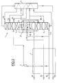
- the installation shown in Figure 1 is intended to produce oxygen at a purity of around 85% under a pressure of around 7.4 x 10⁵ Pa abs. It essentially comprises a double column 1 for air distillation consisting of a medium pressure column (or "MP column") 2 operating at 15.7 x 10⁵ Pa abs. and a low pressure column (or "BP column”) 3 operating at 6.3 x 10⁵ Pa abs, a main heat exchange line 4, a sub-cooler 5, an auxiliary evaporator-condenser 6 and a turbine 7 blowing air into the low pressure column.
- Column 3 is superimposed on column 2 and contains in the tank a vaporizer-condenser 8 and, above this, a second vaporizer-condenser 9.
- the air to be distilled arrives at medium pressure via a line 10 and enters the exchange line 4. Most of this air is cooled to the vicinity of its dew point and leaves the cold end of the line d exchange at an intermediate temperature, expanded at low pressure in the turbine 7 to keep the installation cold, and blown at an intermediate level in the LP column 3.
- a fraction of the fully cooled air is introduced, via a pipe 11, at the base of the column MP 2, and the rest is condensed in the vaporizer-condenser 6; part of the liquid obtained is introduced via a line 12 at an intermediate point in column 2, and the rest is, after sub-cooling in 5 and expansion in an expansion valve 13, introduced at an intermediate point in column BP 3 .
- the "rich liquid” (oxygen-enriched air) collected in the bottom of the MP column is, after sub-cooling in 5 and expansion in an expansion valve 14, introduced at an intermediate point of the LP column.
- “lean liquid” (impure nitrogen) withdrawn at an intermediate point of the column MP is, after sub-cooling in 5 and expansion in an expansion valve 15, introduced at the top of the column BP.
- the almost pure nitrogen produced at the head of the MP column is partly removed from the installation as a product, after heating in the exchange line, via a line 16 and, for the rest, sent in gaseous form. via a line 17, at medium pressure, in the upper evaporator-condenser 9. After condensation, this nitrogen is returned to reflux at the head of the column MP via a line 18.
- impure nitrogen gas drawn off at an intermediate point in column 2 and, in this example, at the same level as the lean liquid, is sent via a line 19, under medium pressure, to the vaporizer-condenser lower 8.
- the liquid thus obtained is returned under reflux to the column MP, at approximately the same level, via a line 20.
- the pump 23 could be omitted, the impure oxygen then being vaporized at 6 under the low pressure.
- the temperature of the bottom liquid of the LP column is determined by that of the gas condensed in this vaporizer-condenser.
- the temperature of the tank liquid, which is impure oxygen is relatively high.
- the pressure of the LP column that is to say the low pressure, can be increased.
- impure oxygen and impure nitrogen are obtained under increased pressure, which makes it possible to make savings on their recovery, for example on the energy required to compress the impure nitrogen to the desired pressure in a gas turbine (not shown) cut at installation, for example as described in the aforementioned US-A-4,224,045.
- the upper vaporizer-condenser 9 serves to provide the necessary reflux at the top of the column MP.
- the impure oxygen is withdrawn in gaseous form from the LP column 3, and is simply reheated in the exchange line 4 before its evacuation goes to the pipe 24. This is particularly advantageous when the impure oxygen is desired under the low pressure. Consequently, the vaporizer-condenser 6 is eliminated.
- a fraction of the medium pressure air, cooled in the vicinity of its dew point, is sent, via a pipe 26, to the lower vaporizer-condenser 8 in place of the intermediate gas of FIG. 1.
- This intermediate gas feeds an intermediate vaporizer-condenser 27 located between the lower vaporizer-condensers 8 and upper 9.
- the liquefied air from the vaporizer-condenser 8 is sent partly, via a line 28, to the column MP and partly, after sub-cooling in 5 and expansion in the expansion valve 13, in the column BP.
- the impure oxygen is withdrawn in liquid form from the tank of the LP column, then is brought by a pump 23 to the desired production pressure, then vaporized and heated under this pressure in the exchange line 4 before being evacuated from the installation via line 24.
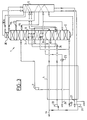
- a nitrogen cycle is provided, known as the rectification support cycle, which is used at the same time to ensure the vaporization of impure oxygen: part of the nitrogen produced at the head of column 3 (which, in this case, has at the head a "minaret" 30 which is supplied at its top with pure liquid nitrogen coming from the upper evaporator-condenser 9 and which, consequently, produces pure nitrogen under low pressure) is, after heating in the exchange line, compressed by a compressor 31 at medium pressure.
- the rectification support cycle which is used at the same time to ensure the vaporization of impure oxygen: part of the nitrogen produced at the head of column 3 (which, in this case, has at the head a "minaret" 30 which is supplied at its top with pure liquid nitrogen coming from the upper evaporator-condenser 9 and which, consequently, produces pure nitrogen under low pressure) is, after heating in the exchange line, compressed by a compressor 31 at medium pressure.
- This medium pressure nitrogen combined with a current of medium pressure nitrogen taken from the line 16, is compressed again by a compressor 33 to a vaporization pressure of the impure oxygen compressed by the pump 23, liquefied in the line of exchange then, after expansion in an expansion valve 34, introduced under reflux at the head of the column MP.
- FIG. 4 also includes a BP 3 column with a minaret 30.
- a BP 3 column with a minaret 30 is high pressure air, boosted to a vaporization pressure of impure oxygen by a booster 35, which ensures the vaporization of the impure oxygen in the exchange line 4.
- this air is, after liquefaction and expansion in an expansion valve 36 and in the expansion valve 13, distributed between the two columns 2 and 3. Consequently, the compressor 33 and the expansion valve 34 of FIG. 3 are eliminated.
- This nitrogen pressure can be chosen between medium pressure and the pressure for which the nitrogen condenses at the cold end of the line exchange.
Abstract
Description
- La présente invention est relative à un procédé de séparation d'air par distillation dans une installation de distillation d'air à double colonne, la double colonne comprenant une colonne moyenne pression et une colonne basse pression.
- EP-A-0.042.676 divulgue un procédé dans lequel :
- on refroidit un débit d'air et on l'envoie à la colonne moyenne pression ;
- on sépare l'air par distillation dans la colonne moyenne pression pour produire un fluide enrichi en oxygène et un fluide enrichi en azote ;
- on envoie lesdits fluides à la colonne basse pression ;
- on soutire un liquide riche en oxygène de la colonne basse pression et on le vaporise; et
- on soutire un gaz enrichi en azote de la colonne basse pression.
- Dans le procédé de EP-A-0.042.676, de l'azote est soutiré de la colonne moyenne pression, réchauffé à la température ambiante, comprimé à une pression élevée, liquéfié et renvoyé à la colonne moyenne pression.
- A cet effet, l'invention a pour objet un procédé caractérisé en ce que :
- on comprime le gaz enrichi en azote soutiré de la colonne basse pression, on le refroidit et on envoie le fluide refroidi à la colonne moyenne pression ;
- on vaporise le liquide riche en oxygène par échange de chaleur avec le débit d'air.
- L'invention a également pour objet un appareil de production de produit gazeux comprenant un compresseur d'air, un échangeur de chaleur, une colonne moyenne pression, une colonne basse pression, des moyens pour envoyer de l'air à la colonne moyenne pression via l'échangeur de chaleur, des moyens pour soutirer un liquide de la cuve de la colonne basse pression et pour envoyer le liquide à l'échangeur de chaleur, caractérisé en ce qu'il comprend un premier compresseur d'azote, des moyens pour envoyer un fluide enrichi en azote de la colonne basse pression au premier compresseur d'azote, du premier compresseur d'azote au moyen de refroidissement du moyen de refroidissement directement ou indirectement à la colonne moyenne pression.
- Suivant d'autres caractéristiques, l'appareil comprend des moyens pour :
- pressuriser le liquide avant de l'envoyer à l'échangeur de chaleur ;
- comprimer un gaz de tête de la colonne moyenne pression et des moyens pour envoyer le gaz de tête comprimé à l'échangeur de chaleur ;
- envoyer le fluide comprimé enrichi en azote à un condenseur de cuve de la colonne basse pression.
- Des exemples de mise en oeuvre de l'invention vont maintenant être décrits en regard des dessins annexés sur lesquels les figures 3 et 4 représentent schématiquement deux modes de réalisation de l'installation de distillation d'air conforme à l'invention et les figures 1 et 2 représentent d'autres modes de réalisation d'une installation de distillation d'air.
- L'installation représentée à la figure 1 est destinée à produire de l'oxygène à une pureté de l'ordre de 85 % sous une pression de l'ordre de 7,4 x 10⁵ Pa abs. Elle comprend essentiellement une double colonne 1 de distillation d'air constituée d'une colonne moyenne pression (ou "colonne MP") 2 fonctionnant sous 15,7 x 10⁵ Pa abs. et d'une colonne basse pression (ou "colonne BP") 3 fonctionnant sous 6,3 x 10⁵ Pa abs, une ligne d'échange thermique principale 4, un sous-refroidisseur 5, un vaporiseur-condenseur auxiliaire 6 et une turbine 7 d'insufflation d'air dans la colonne basse pression. La colonne 3 est superposée à la colonne 2 et contient en cuve un vaporiseur-condenseur 8 et, au-dessus de celui-ci, un second vaporiseur-condenseur 9.
- L'air à distiller arrive sous la moyenne pression via une conduite 10 et pénètre dans la ligne d'échange 4. La majeure partie de cet air est refroidie jusqu'au voisinage de son point de rosée et sort au bout froid de la ligne d'échange à une température intermédiaire, détendu à la basse pression dans la turbine 7 pour assurer le maintien en froid de l'installation, et insufflé à un niveau intermédiaire dans la colonne BP 3.
- Une fraction de l'air entièrement refroidi est introduit, via une conduite 11, à la base de la colonne MP 2, et le reste est condensé dans le vaporiseur-condenseur 6 ; une partie du liquide obtenu est introduite via une conduite 12 en un point intermédiaire de la colonne 2, et le reste est, après sous-refroidissement en 5 et détente dans une vanne de détente 13, introduit en un point intermédiaire de la colonne BP 3.
- Le "liquide riche" (air enrichi en oxygène) recueilli en cuve de la colonne MP est, après sous-refroidissement en 5 et détente dans une vanne de détente 14, introduit en un point intermédiaire de la colonne BP. De même, du "liquide pauvre" (azote impur) soutiré en un point intermédiaire de la colonne MP est, après sous-refroidissement en 5 et détente dans une vanne de détente 15, introduit au sommet de la colonne BP.
- L'azote à peu près pur produit en tête de la colonne MP est pour partie évacué de l'installation en tant que produit, après réchauffement dans la ligne d'échange, via une conduite 16 et, pour le reste, envoyé sous forme gazeuse via une conduite 17, sous la moyenne pression, dans le vaporiseur-condenseur supérieur 9. Après condensation, cet azote est renvoyé en reflux en tête de la colonne MP via une conduite 18.
- De plus, de l'azote impur gazeux, soutiré en un point intermédiaire de la colonne 2 et, dans cet exemple, au même niveau que le liquide pauvre, est envoyé via une conduite 19, sous la moyenne pression, dans le vaporiseur-condenseur inférieur 8. Le liquide ainsi obtenu est renvoyé en reflux dans la colonne MP, à peu près au même niveau, via une conduite 20.
- Les courants de fluides sortant de la double colonne sont :
- au sommet de la colonne MP, de l'azote moyenne pression, dont il a été question plus haut ;
- au sommet de la colonne BP, de l'azote impur, constituant le gaz résiduaire de l'installation. Cet azote impur, après réchauffement dans le sous-refroidisseur 5 et dans la ligne d'échange 4, est évacué va une conduite 21 ; et
- en cuve de la colonne BP, de l'oxygène impur liquide. Ce liquide est soutiré via une conduite 22, comprimé par une pompe 23 à la pression de production (7,4 x 10⁵ Pa abs dans cet exemple), puis vaporisé dans le vaporiseur-condenseur 6 en condensant la fraction d'air moyenne pression qui traverse ce dernier, puis réchauffé sous forme gazeuse dans la ligne d'échange et évacué de l'installation via une conduite de production 24.
- En variante, la pompe 23 pourrait être supprimée, l'oxygène impur étant alors vaporisé en 6 sous la basse pression.
- La description ci-dessus montre que, pour un écart de température donné dans le vaporiseur-condenseur 8, la température du liquide de cuve de la colonne BP est déterminée par celle du gaz condensé dans ce vaporiseur-condenseur. Comme il s'agit d'un gaz intermédiaire de la colonne MP, plus chaud que l'azote de tête de cette colonne, la température du liquide de cuve, qui est l'oxygène impur, est relativement élevée. Par suite, pour une pureté désirée de cet oxygène impur, la pression de la colonne BP, c'est-à-dire la basse pression, peut être augmentée. Finalement, on obtient de l'oxygène impur et de l'azote impur sous une pression accrue, ce qui permet de réaliser des économies sur leur valorisation, par exemple sur l'énergie nécessaire pour comprimer l'azote impur à la pression voulue dans une turbine à gaz (non représentée) coupée à l'installation, par exemple de la manière décrite dans le brevet US-A-4.224.045 précité.
- Dans ce contexte, le vaporiseur-condenseur supérieur 9 sert à fournir le reflux nécessaire en tête de la colonne MP.
- Si les températures des deux gaz alimentant les deux vaporiseurs-condenseurs sont nettement différentes l'une de l'autre, il est nécessaire de prévoir un certain nombre de plateaux de distillation 25 entre ces vaporiseurs-condenseurs. Dans le cas contraire, ces plateaux peuvent être supprimés, ce qui simplifie la construction de la colonne BP, les deux vaporiseurs-condenseurs pouvant même être intégrés en un seul échangeur de chaleur. C'est pourquoi les plateaux 25 ont été représentés en trait interrompu.
- L'installation représentée à la figure 2 ne diffère de la figure 1 que par les points suivants :
- L'oxygène impur est soutiré sous forme gazeuse de la colonne BP 3, et est simplement réchauffé dans la ligne d'échange 4 avant son évacuation va la conduite 24. Ceci est particulièrement intéressant lorsque l'oxygène impur est désiré sous la basse pression. En conséquence, le vaporiseur-condenseur 6 est supprimé.
- De plus, une fraction de l'air moyenne pression, refroidi au voisinage de son point de rosée est envoyée, via une conduite 26, dans le vaporiseur-condenseur inférieur 8 à la place du gaz intermédiaire de la figure 1. Ce gaz intermédiaire, quant à lui, alimente un vaporiseur-condenseur intermédiaire 27 situé entre les vaporiseurs-condenseurs inférieur 8 et supérieur 9. Comme précédemment, il peut y avoir ou non des plateaux entre les paires de vaporiseurs-condenseurs. L'air liquéfié issu du vaporiseur-condenseur 8 est envoyé pour partie, via une conduite 28, dans la colonne MP et pour partie, après sous-refroidissement en 5 et détente dans la vanne de détente 13, dans la colonne BP.
- Par rapport à la solution de la figure 1, on obtient une température plus élevée en cuve de la colonne BP, ce qui est favorable à l'augmentation de la basse pression. En revanche, on doit vaporiser un liquide plus riche en oxygène que l'oxygène impur à produire, ce qui tend à réduire la basse pression.
- Ce dernier inconvénient est supprimé dans l'installation de la figure 3 qui permet de produire l'oxygène impur sous une pression élevée, et qui diffère de la précédente par les points suivants :
- D'une part, l'oxygène impur est soutiré sous forme liquide de la cuve de la colonne BP, puis est amené par une pompe 23 à la pression de production désirée, puis vaporisé et réchauffé sous cette pression dans la ligne d'échange 4 avant d'être évacué de l'installation via la conduite 24.
- D'autre part, pour compenser la perte de reflux dans la colonne MP résultant du soutirage d'oxygène liquide en cuve de la colonne BP, il est prévu un cycle azote, dit cycle de soutien de rectification, qui est utilisé en même temps pour assurer la vaporisation de l'oxygène impur : une partie de l'azote produit en tête de la colonne 3 (laquelle, dans ce cas, possède en tête un "minaret" 30 qui est alimenté à son sommet par de l'azote liquide pur provenant du vaporiseur-condenseur supérieur 9 et qui, par suite, produit de l'azote pur sous la basse pression) est, après réchauffement dans la ligne d'échange, comprimée par un compresseur 31 à la moyenne pression. Cet azote moyenne pression, réuni à un courant d'azote moyenne pression prélevé sur la conduite 16, est comprimé de nouveau par un compresseur 33 à une pression de vaporisation de l'oxygène impur comprimé par la pompe 23, liquéfié dans la ligne d'échange puis, après détente dans une vanne de détente 34, introduit en reflux en tête de la colonne MP.
- L'installation de la figure 4 comporte également une colonne BP 3 à minaret 30. Toutefois, contrairement au cas précédent, c'est de l'air haute pression, surpressé à une pression de vaporisation de l'oxygène impur par un surpresseur 35, qui assure la vaporisation de l'oxygène impur dans la ligne d'échange 4. Dans cet exemple, cet air est, après liquéfaction et détente dans une vanne de détente 36 et dans la vanne de détente 13, réparti entre les deux colonnes 2 et 3. Par conséquent, le compresseur 33 et la vanne de détente 34 de la figure 3 sont supprimés.
- De plus, l'azote issu du compresseur 31, comprimé à une pression supérieure à la moyenne pression, alimente sous forme gazeuse, après refroidissement dans la ligne d'échange, le vaporiseur-condenseur inférieur 8, et l'azote liquide résultant est, après détente dans une vanne de détente 37, réuni à l'azote liquide moyenne pression issu du vaporiseur-condenseur supérieur 9. Ceci présente l'avantage de permettre un réglage de la température de la cuve de la colonne BP, et donc de la pression de cette colonne, par réglage de la pression de l'azote alimentant le vaporiseur-condenseur 8. Cette pression d'azote peut être choisie entre la moyenne pression et la pression pour laquelle l'azote se condense au bout froid de la ligne d'échange.
Claims (11)
- Procédé de production d'oxygène par distillation d'air dans une installation de distillation d'air à double colonne (1), la double colonne comprenant une colonne moyenne pression (2) et une colonne basse pression (3), dans lequel :- on refroidit un débit d'air et on l'envoie à la colonne moyenne pression (2) ;- on sépare l'air par distillation dans la colonne moyenne pression en un fluide enrichi en oxygène et un fluide enrichi en azote ;- on envoie lesdits fluides à la colonne basse pression ;- on soutire un liquide riche en oxygène de la colonne basse pression et on le vaporise ;- on soutire un gaz enrichi en azote de la colonne basse pression, caractérisé en ce que :- on comprime le gaz enrichi en azote soutiré de la colonne basse pression, on le refroidit et on envoie le fluide refroidi à la colonne moyenne pression ;- on vaporise le liquide riche en oxygène par échange de chaleur avec le débit d'air.
- Procédé selon la revendication 1 dans lequel on vaporise le liquide en oxygène par échange de chaleur avec le gaz comprimé enrichi en azote.
- Procédé selon la revendication 1 ou 2, dans lequel le gaz enrichi en azote est réchauffé avant d'être comprimé.
- Procédé selon la revendication 1, 2 ou 3, dans lequel on vaporise le liquide riche en oxygène contre une partie de la vapeur enrichie en azote qui a été comprimée.
- Procédé selon l'une des revendications précédentes dans lequel le gaz enrichi en azote se liquéfie par échange de chaleur avec le liquide riche en oxygène.
- Procédé selon l'une des revendications 1 à 4 dans lequel le gaz enrichi en azote comprimé et refroidi est envoyé à un condenseur-vaporiseur (8) de la colonne basse pression où il se condense pour former du reflux.
- Appareil de production de produit gazeux comprenant :- un compresseur d'air ;- un échangeur de chaleur (4) ;- une colonne moyenne pression (2) ;- une colonne basse pression (3) ;- des moyens pour envoyer de l'air à la colonne moyenne pression via l'échangeur de chaleur ;- des moyens pour soutirer un liquide de la cuve de la colonne basse pression et pour envoyer le liquide à l'échangeur de chaleur,caractérisé en ce qu'il comprend un premier compresseur d'azote (31), des moyens pour envoyer un fluide enrichi en azote de la colonne basse pression au premier compresseur d'azote, du premier compresseur d'azote au moyen de refroidissement (4) du moyen de refroidissement (4) directement ou indirectement à la colonne moyenne pression.
- Appareil selon la revendication 7 comprenant des moyens pour pressuriser le liquide avant de l'envoyer à l'échangeur de chaleur (4).
- Appareil selon l'une des revendications 7 et 8 dans lequel on envoie le fluide enrichi en azote du premier compresseur d'azote à un moyen de refroidissement (4) constitué par l'échangeur de chaleur.
- Appareil selon l'une des revendications 7, 8 ou 9 comprenant des moyens pour comprimer un gaz de tête de la colonne moyenne pression (2) et des moyens pour envoyer le gaz de tête comprimé à l'échangeur de chaleur (4).
- Appareil selon l'une des revendications 7, 8 ou 9 comprenant des moyens pour envoyer le fluide comprimé enrichi en azote de l'échangeur de chaleur à un condenseur de cuve (8) de la colonne basse pression et ensuite à la colonne moyenne pression (2).
Applications Claiming Priority (3)
| Application Number | Priority Date | Filing Date | Title |
|---|---|---|---|
| FR9115705 | 1991-12-18 | ||
| FR9115705A FR2685459B1 (fr) | 1991-12-18 | 1991-12-18 | Procede et installation de production d'oxygene impur. |
| EP92403330A EP0547946B2 (fr) | 1991-12-18 | 1992-12-09 | Procédé de production d'oxygène impur |
Related Parent Applications (2)
| Application Number | Title | Priority Date | Filing Date |
|---|---|---|---|
| EP92403330.1 Division | 1992-12-09 | ||
| EP92403330A Division EP0547946B2 (fr) | 1991-12-18 | 1992-12-09 | Procédé de production d'oxygène impur |
Publications (2)
| Publication Number | Publication Date |
|---|---|
| EP0713069A1 true EP0713069A1 (fr) | 1996-05-22 |
| EP0713069B1 EP0713069B1 (fr) | 2000-04-26 |
Family
ID=9420168
Family Applications (2)
| Application Number | Title | Priority Date | Filing Date |
|---|---|---|---|
| EP96200235A Expired - Lifetime EP0713069B1 (fr) | 1991-12-18 | 1992-12-09 | Procédé et installation de séparation d'air |
| EP92403330A Expired - Lifetime EP0547946B2 (fr) | 1991-12-18 | 1992-12-09 | Procédé de production d'oxygène impur |
Family Applications After (1)
| Application Number | Title | Priority Date | Filing Date |
|---|---|---|---|
| EP92403330A Expired - Lifetime EP0547946B2 (fr) | 1991-12-18 | 1992-12-09 | Procédé de production d'oxygène impur |
Country Status (9)
| Country | Link |
|---|---|
| US (1) | US5392609A (fr) |
| EP (2) | EP0713069B1 (fr) |
| CN (1) | CN1068428C (fr) |
| AU (1) | AU654601B2 (fr) |
| BR (1) | BR9205050A (fr) |
| CA (1) | CA2085561A1 (fr) |
| DE (2) | DE69214409T3 (fr) |
| ES (2) | ES2145967T3 (fr) |
| FR (1) | FR2685459B1 (fr) |
Cited By (2)
| Publication number | Priority date | Publication date | Assignee | Title |
|---|---|---|---|---|
| EP0834712A2 (fr) * | 1996-10-01 | 1998-04-08 | Air Products And Chemicals, Inc. | Procédé de production d'azote à haute pression en utilisant une colonne à pression plus élevée et une ou plusieurs colonnes à pression plus haute |
| EP1099922A2 (fr) * | 1999-11-09 | 2001-05-16 | Air Products And Chemicals, Inc. | Procédé de la production d'oxygène de pression intermédiaire |
Families Citing this family (26)
| Publication number | Priority date | Publication date | Assignee | Title |
|---|---|---|---|---|
| US5251451A (en) * | 1992-08-28 | 1993-10-12 | Air Products And Chemicals, Inc. | Multiple reboiler, double column, air boosted, elevated pressure air separation cycle and its integration with gas turbines |
| US5355682A (en) * | 1993-09-15 | 1994-10-18 | Air Products And Chemicals, Inc. | Cryogenic air separation process producing elevated pressure nitrogen by pumped liquid nitrogen |
| US5454227A (en) * | 1994-08-17 | 1995-10-03 | The Boc Group, Inc. | Air separation method and apparatus |
| US5463871A (en) * | 1994-10-04 | 1995-11-07 | Praxair Technology, Inc. | Side column cryogenic rectification system for producing lower purity oxygen |
| DE19609490A1 (de) * | 1995-03-10 | 1996-09-12 | Linde Ag | Verfahren und Vorrichtung zur Tieftemperaturzerlegung von Luft |
| US5546767A (en) * | 1995-09-29 | 1996-08-20 | Praxair Technology, Inc. | Cryogenic rectification system for producing dual purity oxygen |
| US5600970A (en) * | 1995-12-19 | 1997-02-11 | Praxair Technology, Inc. | Cryogenic rectification system with nitrogen turboexpander heat pump |
| US5611219A (en) * | 1996-03-19 | 1997-03-18 | Praxair Technology, Inc. | Air boiling cryogenic rectification system with staged feed air condensation |
| US5666824A (en) * | 1996-03-19 | 1997-09-16 | Praxair Technology, Inc. | Cryogenic rectification system with staged feed air condensation |
| US5678427A (en) * | 1996-06-27 | 1997-10-21 | Praxair Technology, Inc. | Cryogenic rectification system for producing low purity oxygen and high purity nitrogen |
| US5669236A (en) * | 1996-08-05 | 1997-09-23 | Praxair Technology, Inc. | Cryogenic rectification system for producing low purity oxygen and high purity oxygen |
| US5664438A (en) * | 1996-08-13 | 1997-09-09 | Praxair Technology, Inc. | Cryogenic side column rectification system for producing low purity oxygen and high purity nitrogen |
| US5675977A (en) * | 1996-11-07 | 1997-10-14 | Praxair Technology, Inc. | Cryogenic rectification system with kettle liquid column |
| US5761927A (en) * | 1997-04-29 | 1998-06-09 | Air Products And Chemicals, Inc. | Process to produce nitrogen using a double column and three reboiler/condensers |
| US5836175A (en) * | 1997-08-29 | 1998-11-17 | Praxair Technology, Inc. | Dual column cryogenic rectification system for producing nitrogen |
| US5839296A (en) * | 1997-09-09 | 1998-11-24 | Praxair Technology, Inc. | High pressure, improved efficiency cryogenic rectification system for low purity oxygen production |
| CN1143946C (zh) | 1997-09-26 | 2004-03-31 | 西门子公司 | 叶片机械用壳体 |
| US5806342A (en) * | 1997-10-15 | 1998-09-15 | Praxair Technology, Inc. | Cryogenic rectification system for producing low purity oxygen and high purity oxygen |
| US5956972A (en) * | 1997-12-23 | 1999-09-28 | The Boc Group, Inc. | Method of operating a lower pressure column of a double column distillation unit |
| DE10139727A1 (de) | 2001-08-13 | 2003-02-27 | Linde Ag | Verfahren und Vorrichtung zur Gewinnung eines Druckprodukts durch Tieftemperaturzerlegung von Luft |
| DE10205878A1 (de) * | 2002-02-13 | 2003-08-21 | Linde Ag | Tieftemperatur-Luftzerlegungsverfahren |
| FR2930330B1 (fr) * | 2008-04-22 | 2013-09-13 | Air Liquide | Procede et appareil de separation d'air par distillation cryogenique |
| FR2973865B1 (fr) | 2011-04-08 | 2015-11-06 | Air Liquide | Procede et appareil de separation d'air par distillation cryogenique |
| US9453674B2 (en) * | 2013-12-16 | 2016-09-27 | Praxair Technology, Inc. | Main heat exchange system and method for reboiling |
| CN106989567A (zh) * | 2017-04-25 | 2017-07-28 | 河南开元空分集团有限公司 | 一种低能耗的同时生产富氧气体和高纯氮气的装置和方法 |
| AU2018269511A1 (en) | 2017-05-16 | 2019-11-28 | Terrence J. Ebert | Apparatus and process for liquefying gases |
Citations (2)
| Publication number | Priority date | Publication date | Assignee | Title |
|---|---|---|---|---|
| EP0042676A1 (fr) * | 1980-06-17 | 1981-12-30 | Air Products And Chemicals, Inc. | Méthode de production d'oxygène gazeux et installation cryogénique pour la mise en oeuvre de cette méthode |
| EP0384483A2 (fr) * | 1989-02-23 | 1990-08-29 | Linde Aktiengesellschaft | Procédé et dispositif de rectification d'air |
Family Cites Families (10)
| Publication number | Priority date | Publication date | Assignee | Title |
|---|---|---|---|---|
| US3210951A (en) * | 1960-08-25 | 1965-10-12 | Air Prod & Chem | Method for low temperature separation of gaseous mixtures |
| FR2461906A1 (fr) * | 1979-07-20 | 1981-02-06 | Air Liquide | Procede et installation cryogeniques de separation d'air avec production d'oxygene sous haute pression |
| JPS56124879A (en) * | 1980-02-26 | 1981-09-30 | Kobe Steel Ltd | Air liquefying and separating method and apparatus |
| US4448595A (en) * | 1982-12-02 | 1984-05-15 | Union Carbide Corporation | Split column multiple condenser-reboiler air separation process |
| US4453957A (en) * | 1982-12-02 | 1984-06-12 | Union Carbide Corporation | Double column multiple condenser-reboiler high pressure nitrogen process |
| JPS61190277A (ja) * | 1985-02-16 | 1986-08-23 | 大同酸素株式会社 | 高純度窒素および酸素ガス製造装置 |
| US4704147A (en) * | 1986-08-20 | 1987-11-03 | Air Products And Chemicals, Inc. | Dual air pressure cycle to produce low purity oxygen |
| US4936099A (en) * | 1989-05-19 | 1990-06-26 | Air Products And Chemicals, Inc. | Air separation process for the production of oxygen-rich and nitrogen-rich products |
| US5006137A (en) * | 1990-03-09 | 1991-04-09 | Air Products And Chemicals, Inc. | Nitrogen generator with dual reboiler/condensers in the low pressure distillation column |
| US5069699A (en) * | 1990-09-20 | 1991-12-03 | Air Products And Chemicals, Inc. | Triple distillation column nitrogen generator with plural reboiler/condensers |
-
1991
- 1991-12-18 FR FR9115705A patent/FR2685459B1/fr not_active Expired - Fee Related
-
1992
- 1992-12-09 EP EP96200235A patent/EP0713069B1/fr not_active Expired - Lifetime
- 1992-12-09 ES ES96200235T patent/ES2145967T3/es not_active Expired - Lifetime
- 1992-12-09 DE DE69214409T patent/DE69214409T3/de not_active Expired - Fee Related
- 1992-12-09 ES ES92403330T patent/ES2092661T3/es not_active Expired - Lifetime
- 1992-12-09 DE DE69230975T patent/DE69230975T2/de not_active Expired - Fee Related
- 1992-12-09 EP EP92403330A patent/EP0547946B2/fr not_active Expired - Lifetime
- 1992-12-14 US US07/990,100 patent/US5392609A/en not_active Expired - Fee Related
- 1992-12-16 CA CA002085561A patent/CA2085561A1/fr not_active Abandoned
- 1992-12-17 BR BR9205050A patent/BR9205050A/pt not_active IP Right Cessation
- 1992-12-17 AU AU30221/92A patent/AU654601B2/en not_active Ceased
- 1992-12-17 CN CN92114490.3A patent/CN1068428C/zh not_active Expired - Fee Related
Patent Citations (2)
| Publication number | Priority date | Publication date | Assignee | Title |
|---|---|---|---|---|
| EP0042676A1 (fr) * | 1980-06-17 | 1981-12-30 | Air Products And Chemicals, Inc. | Méthode de production d'oxygène gazeux et installation cryogénique pour la mise en oeuvre de cette méthode |
| EP0384483A2 (fr) * | 1989-02-23 | 1990-08-29 | Linde Aktiengesellschaft | Procédé et dispositif de rectification d'air |
Cited By (4)
| Publication number | Priority date | Publication date | Assignee | Title |
|---|---|---|---|---|
| EP0834712A2 (fr) * | 1996-10-01 | 1998-04-08 | Air Products And Chemicals, Inc. | Procédé de production d'azote à haute pression en utilisant une colonne à pression plus élevée et une ou plusieurs colonnes à pression plus haute |
| EP0834712A3 (fr) * | 1996-10-01 | 1998-10-21 | Air Products And Chemicals, Inc. | Procédé de production d'azote à haute pression en utilisant une colonne à pression plus élevée et une ou plusieurs colonnes à pression plus haute |
| EP1099922A2 (fr) * | 1999-11-09 | 2001-05-16 | Air Products And Chemicals, Inc. | Procédé de la production d'oxygène de pression intermédiaire |
| EP1099922B1 (fr) * | 1999-11-09 | 2006-05-24 | Air Products And Chemicals, Inc. | Procédé de la production d'oxygène de pression intermédiaire |
Also Published As
| Publication number | Publication date |
|---|---|
| AU3022192A (en) | 1993-06-24 |
| DE69230975T2 (de) | 2000-10-05 |
| EP0547946B1 (fr) | 1996-10-09 |
| CA2085561A1 (fr) | 1993-06-19 |
| DE69214409D1 (de) | 1996-11-14 |
| US5392609A (en) | 1995-02-28 |
| FR2685459A1 (fr) | 1993-06-25 |
| AU654601B2 (en) | 1994-11-10 |
| CN1068428C (zh) | 2001-07-11 |
| EP0547946B2 (fr) | 2000-03-22 |
| BR9205050A (pt) | 1993-08-10 |
| CN1088301A (zh) | 1994-06-22 |
| ES2092661T3 (es) | 1996-12-01 |
| DE69214409T3 (de) | 2000-07-13 |
| EP0713069B1 (fr) | 2000-04-26 |
| DE69214409T2 (de) | 1997-05-22 |
| EP0547946A1 (fr) | 1993-06-23 |
| ES2145967T3 (es) | 2000-07-16 |
| FR2685459B1 (fr) | 1994-02-11 |
| DE69230975D1 (de) | 2000-05-31 |
Similar Documents
| Publication | Publication Date | Title |
|---|---|---|
| EP0713069B1 (fr) | Procédé et installation de séparation d'air | |
| EP0689019B1 (fr) | Procédé et installation de production d'oxygène gazeux sous pression | |
| JP4331460B2 (ja) | 低温空気分離によるクリプトン及び/又はキセノンの製造方法及び装置 | |
| EP0628778B2 (fr) | Procédé et unité de fourniture d'un gaz sous pression à une installation consommatrice d'un constituant de l'air | |
| EP2122282B1 (fr) | Procédé de séparation d'un mélange de monoxyde de carbone, de méthane, d'hydrogène et d'azote par distillation cryogénique | |
| JPH06117753A (ja) | 空気の高圧低温蒸留方法 | |
| EP0610972B1 (fr) | Procédé de production d'azote | |
| JPH10227560A (ja) | 空気分離方法 | |
| EP2847060A2 (fr) | Procédé et appareil de séparation d'air par distillation cryogénique | |
| JP2000055542A (ja) | 低温空気分離によるアルゴン製造方法 | |
| EP0611936B1 (fr) | Procédé et installation de production d'azote ultra-pur par distillation d'air | |
| EP2504646B1 (fr) | Procédé et appareil de séparation cryogénique d'un mélange d'azote et de monoxyde de carbone | |
| EP0677713B1 (fr) | Procédé et installation pour la production de l'oxygène par distillation de l'air | |
| EP1446620A1 (fr) | Procede et installation de production d'helium | |
| EP0732556B1 (fr) | Procédé et appareil de vaporisation d'un débit liquide | |
| EP0595673B1 (fr) | Procédé et installation de production d'azote et d'oxygène | |
| EP0611218B2 (fr) | Procédé et installation de production d'oxygene sous pression | |
| EP0612967B1 (fr) | Procédé de production d'oxygène et/ou d'azote sous pression | |
| JPH08170876A (ja) | 冷却蒸留による酸素の製造方法及び装置 | |
| EP1132700B1 (fr) | Procédé et installation de séparation d'air par distillation cryogénique | |
| US6385996B2 (en) | Process and installation for separation of air by cryogenic distillation | |
| FR2787561A1 (fr) | Procede de separation d'air par distillation cryogenique | |
| WO2009136077A2 (fr) | Procede et appareil de separation d'air par distillation cryogenique | |
| FR2795496A1 (fr) | Appareil et procede de separation d'air par distillation cryogenique | |
| FR2764681A1 (fr) | Procede et installation de separation d'air par distillation cryogenique |
Legal Events
| Date | Code | Title | Description |
|---|---|---|---|
| PUAI | Public reference made under article 153(3) epc to a published international application that has entered the european phase |
Free format text: ORIGINAL CODE: 0009012 |
|
| AC | Divisional application: reference to earlier application |
Ref document number: 547946 Country of ref document: EP |
|
| AK | Designated contracting states |
Kind code of ref document: A1 Designated state(s): BE DE ES FR GB IT NL SE |
|
| 17P | Request for examination filed |
Effective date: 19961122 |
|
| 17Q | First examination report despatched |
Effective date: 19980525 |
|
| GRAG | Despatch of communication of intention to grant |
Free format text: ORIGINAL CODE: EPIDOS AGRA |
|
| GRAG | Despatch of communication of intention to grant |
Free format text: ORIGINAL CODE: EPIDOS AGRA |
|
| GRAH | Despatch of communication of intention to grant a patent |
Free format text: ORIGINAL CODE: EPIDOS IGRA |
|
| GRAH | Despatch of communication of intention to grant a patent |
Free format text: ORIGINAL CODE: EPIDOS IGRA |
|
| GRAA | (expected) grant |
Free format text: ORIGINAL CODE: 0009210 |
|
| AC | Divisional application: reference to earlier application |
Ref document number: 547946 Country of ref document: EP |
|
| AK | Designated contracting states |
Kind code of ref document: B1 Designated state(s): BE DE ES FR GB IT NL SE |
|
| ITF | It: translation for a ep patent filed |
Owner name: JACOBACCI & PERANI S.P.A. |
|
| REF | Corresponds to: |
Ref document number: 69230975 Country of ref document: DE Date of ref document: 20000531 |
|
| GBT | Gb: translation of ep patent filed (gb section 77(6)(a)/1977) |
Effective date: 20000523 |
|
| REG | Reference to a national code |
Ref country code: ES Ref legal event code: FG2A Ref document number: 2145967 Country of ref document: ES Kind code of ref document: T3 |
|
| PLBE | No opposition filed within time limit |
Free format text: ORIGINAL CODE: 0009261 |
|
| STAA | Information on the status of an ep patent application or granted ep patent |
Free format text: STATUS: NO OPPOSITION FILED WITHIN TIME LIMIT |
|
| 26N | No opposition filed | ||
| PGFP | Annual fee paid to national office [announced via postgrant information from national office to epo] |
Ref country code: FR Payment date: 20011112 Year of fee payment: 10 |
|
| PGFP | Annual fee paid to national office [announced via postgrant information from national office to epo] |
Ref country code: SE Payment date: 20011116 Year of fee payment: 10 |
|
| PGFP | Annual fee paid to national office [announced via postgrant information from national office to epo] |
Ref country code: GB Payment date: 20011119 Year of fee payment: 10 |
|
| PGFP | Annual fee paid to national office [announced via postgrant information from national office to epo] |
Ref country code: NL Payment date: 20011120 Year of fee payment: 10 |
|
| PGFP | Annual fee paid to national office [announced via postgrant information from national office to epo] |
Ref country code: DE Payment date: 20011126 Year of fee payment: 10 |
|
| PGFP | Annual fee paid to national office [announced via postgrant information from national office to epo] |
Ref country code: ES Payment date: 20011211 Year of fee payment: 10 |
|
| PGFP | Annual fee paid to national office [announced via postgrant information from national office to epo] |
Ref country code: BE Payment date: 20011219 Year of fee payment: 10 |
|
| REG | Reference to a national code |
Ref country code: GB Ref legal event code: IF02 |
|
| PG25 | Lapsed in a contracting state [announced via postgrant information from national office to epo] |
Ref country code: GB Free format text: LAPSE BECAUSE OF NON-PAYMENT OF DUE FEES Effective date: 20021209 |
|
| PG25 | Lapsed in a contracting state [announced via postgrant information from national office to epo] |
Ref country code: SE Free format text: LAPSE BECAUSE OF NON-PAYMENT OF DUE FEES Effective date: 20021210 Ref country code: ES Free format text: LAPSE BECAUSE OF NON-PAYMENT OF DUE FEES Effective date: 20021210 |
|
| PG25 | Lapsed in a contracting state [announced via postgrant information from national office to epo] |
Ref country code: BE Free format text: LAPSE BECAUSE OF NON-PAYMENT OF DUE FEES Effective date: 20021231 |
|
| BERE | Be: lapsed |
Owner name: S.A. L'*AIR LIQUIDE POUR L'ETUDE ET L'EXPLOITATION Effective date: 20021231 |
|
| PG25 | Lapsed in a contracting state [announced via postgrant information from national office to epo] |
Ref country code: NL Free format text: LAPSE BECAUSE OF NON-PAYMENT OF DUE FEES Effective date: 20030701 Ref country code: DE Free format text: LAPSE BECAUSE OF NON-PAYMENT OF DUE FEES Effective date: 20030701 |
|
| EUG | Se: european patent has lapsed | ||
| GBPC | Gb: european patent ceased through non-payment of renewal fee | ||
| NLV4 | Nl: lapsed or anulled due to non-payment of the annual fee |
Effective date: 20030701 |
|
| PG25 | Lapsed in a contracting state [announced via postgrant information from national office to epo] |
Ref country code: FR Free format text: LAPSE BECAUSE OF NON-PAYMENT OF DUE FEES Effective date: 20030901 |
|
| REG | Reference to a national code |
Ref country code: FR Ref legal event code: ST |
|
| REG | Reference to a national code |
Ref country code: ES Ref legal event code: FD2A Effective date: 20021210 |
|
| PG25 | Lapsed in a contracting state [announced via postgrant information from national office to epo] |
Ref country code: IT Free format text: LAPSE BECAUSE OF NON-PAYMENT OF DUE FEES;WARNING: LAPSES OF ITALIAN PATENTS WITH EFFECTIVE DATE BEFORE 2007 MAY HAVE OCCURRED AT ANY TIME BEFORE 2007. THE CORRECT EFFECTIVE DATE MAY BE DIFFERENT FROM THE ONE RECORDED. Effective date: 20051209 |