EP0711684B1 - Porte-bagages de toit - Google Patents
Porte-bagages de toit Download PDFInfo
- Publication number
- EP0711684B1 EP0711684B1 EP95115530A EP95115530A EP0711684B1 EP 0711684 B1 EP0711684 B1 EP 0711684B1 EP 95115530 A EP95115530 A EP 95115530A EP 95115530 A EP95115530 A EP 95115530A EP 0711684 B1 EP0711684 B1 EP 0711684B1
- Authority
- EP
- European Patent Office
- Prior art keywords
- roof rack
- rack according
- lateral frame
- vehicle
- receiving means
- Prior art date
- Legal status (The legal status is an assumption and is not a legal conclusion. Google has not performed a legal analysis and makes no representation as to the accuracy of the status listed.)
- Expired - Lifetime
Links
Images

Classifications
-
- B—PERFORMING OPERATIONS; TRANSPORTING
- B60—VEHICLES IN GENERAL
- B60R—VEHICLES, VEHICLE FITTINGS, OR VEHICLE PARTS, NOT OTHERWISE PROVIDED FOR
- B60R9/00—Supplementary fittings on vehicle exterior for carrying loads, e.g. luggage, sports gear or the like
Definitions
- the invention relates to a roof rack on a passenger car, in particular Cabriolet, the two extending in the vehicle longitudinal direction lateral frame parts and transverse support elements fixed to them comprises, the two side frame parts releasably on the adjacent Structure of the passenger car are held in place.
- a roof rack of the type mentioned comes from the German Utility model G 87 14 471.9. This describes a roof rack for convertibles that consist of two spaced from each other Longitudinal struts and crossmember struts fixed on these. These longitudinal beam struts are on the one hand on the A-pillar and on the other hand on the B-pillar or the roll bar attached.
- a roof rack for a convertible is known, whose rear feet for support on the vehicle in the joint of the Trunk lid and its front feet for support on the roof frame in the Area of the A-pillar or in the joint of the bonnet.
- the roof rack of both fonts are made of round or rectangular Hollow sections assembled and designed as a pivoting roof support to a Fold the folding top back and forth with the roof load carrier attached enable.
- a disadvantage of these known roof rack is that by their manufacture from round or rectangular hollow profiles complex welding and Riveted joints or additional fasteners are required both the torsional stiffness and the maximum load capacity of the Reduce the roof rack.
- the object of the invention is to provide a roof rack of the type mentioned so that the disadvantages listed are avoided, which for the Vehicle maximum possible and permissible roof load can be absorbed and the Roof rack can be designed so that the visual appearance of the Vehicle is positively influenced with the roof rack attached.
- the production of the side frame parts from die-casting enables one Design of the frame profile according to the local mechanical Conditions.
- the side frame parts are in one piece with foot sections for fastening on the vehicle and support sections for fastening the transverse Carrying elements executed.
- a hollow profile open to the median longitudinal plane of a Light metal alloy allows the design of the side Frame parts so that with a pleasing appearance and light weight the required mechanical strength is achieved.
- the die-cast fabrication also enables the side frame parts stylistically in such a way that the visual appearance of the vehicle mounted roof rack is positively influenced.
- the side frame parts follow the vehicle contour at an even distance, resulting in a compact design results.
- the roof rack is attached to the passenger car via specially designed recordings on both sides of the vehicle at the top End of the windshield frame (A pillar) and at the top of the Part of the rear side, on those that match the pictures, on the foot ends of the lateral frame parts attached retaining elements are attached.
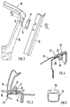
- FIG. 1 shows one half of a roof rack 1 for a passenger car, in particular a convertible or an open top with a hardtop Vehicle.
- Two lateral ones extending in the longitudinal direction of the vehicle Frame parts 2 (one is shown in FIG. 1) have foot sections 3, 4 which are used for Attach the roof rack 1 to the vehicle body.
- Integral the side frame parts 2 are support sections 5 for transverse Support elements 9 attached. These spaced apart support portions 5 are designed so that the transverse support members 9 from each other have a sufficient distance to fasten longer loads and at horizontally standing vehicle come to rest in a horizontal plane.
- the two support sections 5 are each angular and set consist of a first upright section 6 and a second transverse section 7 together, the second section 7 approximately is aligned horizontally and with its free end 8 in the direction Vehicle longitudinal median plane extends.
- the front receptacles 11 are on an upper, laterally outer Area of the windshield frame 10 attached. Like Figures 2 and 3 show, the receptacles 11 lie behind the door sealing profile 13 in one Area that is only accessible when the side vehicle door is open (Theft protection).
- the receptacles 11 consist of screw fastenings 15 impressions 14 on the A-pillar 16. Each screw fastening 15 comprises two weld nuts 21 held in position in the impression 14, into which Fastening screws 22 are screwed in.
- This connecting part 18 can be integral on the side frame part 2 cast, but also be formed separately.
- Fig. 4 shows a rear, each formed on the rear side parts 19 Recording 12 for the rear foot portion 4 of a side frame part 2 of the Roof rack 1.
- the rear side part 19 has a local depression 20 and two in the area of Recess 20 attached weld nuts 21 (one shown).
- weld nuts 21 are screws 22 that have a conical screw head 23 have turned.
- the rear foot sections 4 are comparable to the front foot sections 3 Can be fixed to the body using connecting parts using screws.
- the Connecting parts can in turn be integral on the side frame part 2 cast on, or also be formed separately.
- the receptacle 12 is supported by a roof carrier 1 not installed Slider 24, which with the conical head portions 23 of the screws 22nd cooperates, covered.
- the slider 24 is comparable to the filler 17th only when the side vehicle door is open in the vehicle's longitudinal direction into one Release position movable and then removable (anti-theft protection).
- Rear Foot section 4 of the roof rack 1 is either by the screws 22 or can be fixed by differently shaped screws on the receptacle 12
- the cross-sectional profile of the side frame parts 2 is in accordance with the Load of the roof rack 1 designed forces; it is expanding from the windshield frame 9 continuously towards the rear and has one curved course.
- the curved course is rough for optical reasons adapted to the course of the adjacent edge area of the door window pane.
- the side frame parts 2 are made of a light metal alloy (Mg, Al Alloy) and have a relatively thin wall thickness (approx. 3mm to 4mm).
- the transverse support elements 9 fastened to the support sections 5 of the side frame parts 2 consist of hollow extruded profiles (see FIG. 5), which has a receiving groove 25 for commercially available special holders, such as for roof boxes, skis, bicycles, surfboards, etc.
- the extruded profiles are closed at their lateral ends by inserted cover elements 26 and can be locked (theft protection).
Landscapes
- Engineering & Computer Science (AREA)
- Mechanical Engineering (AREA)
- Body Structure For Vehicles (AREA)
- Fittings On The Vehicle Exterior For Carrying Loads, And Devices For Holding Or Mounting Articles (AREA)
Claims (11)
- Porte-bagage de toit d'une voiture de tourisme en particulier d'un cabriolet qui comprend deux parties de cadre (2) latérales s'étendant dans le sens de la longueur du véhicule et des éléments porteurs (9) s'étendant transversalement fixés sur celles-ci, les deux parties de cadre (2) latérales étant maintenues en position de manière amovible sur la carrosserie adjacente de la voiture de tourisme, caractérisé en ce que les parties de cadre (2) latérales sont formées par des pièces moulées sous pression de grande surface, chaque partie de cadre (2) latérale présentant une portion d'appui (5) avant et une portion d'appui (5) arrière, formées d'un seul tenant sur lesquelles reposent et sont fixés les éléments porteurs (9) transversaux.
- Porte-bagage de toit selon la revendication 1, caractérisé en ce que les deux portions d'appui (5) sont chacune en forme d'équerre et se composent d'une première partie (6) s'étendant verticalement et d'une deuxième partie (7) transversale, la deuxième partie (7) étant orientée à peu près horizontalement et s'étendant avec son extrémité libre (8) en direction du plan médian longitudinal du véhicule.
- Porte-bagage de toit selon la revendication 1, caractérisé en ce qu'une extrémité avant de la partie de cadre (2) latérale est fixée de manière amovible, par une portion de pied (3) placée dessus, sur un logement (11) du cadre (10) du pare-brise.
- Porte-bagage de toit selon la revendication 3, caractérisé en ce que le logement (11) prévu sur un montant A (16) du cadre (10) du pare-brise, n'est accessible que lorsque la portière latérale du véhicule est ouverte.
- Porte-bagage de toit selon les revendications 3 et 4, caractérisé en ce que dans le cas où le porte-bagage de toit (1) n'est pas mis en place, une pièce de remplissage (17) est insérée dans le logement (11), pièce qui est enlevée lors du montage du porte-bagage de toit (1).
- Porte-bagage de toit selon la revendication 1, caractérisé en ce qu'une extrémité arrière de la partie de cadre (2) latérale est fixée de manière amovible sur un logement (12), formé sur la face supérieure de la partie latérale arrière (19).
- Porte-bagage de toit selon la revendication 6, caractérisé en ce que les logements (12), formés sur la partie latérale arrière (19), sont recouverts par un coulisseau (24) dans leur position de non-utilisation et en ce que le coulisseau (24) est déplaçable dans une position de libération, uniquement lorsque la portière latérale du véhicule est ouverte.
- Porte-bagage de toit selon une ou plusieurs des revendications précédentes, caractérisé en ce que la section transversale de la partie de cadre (2) latérale s'élargit en continu depuis le cadre (10) du pare-brise vers l'arrière et en ce que la partie de cadre (2) présente un parcours en arc, qui correspond à peu près au parcours de la zone de bordure adjacente de la vitre de portière.
- Porte-bagage de toit selon la revendication 2, caractérisé en ce que la première portion d'appui (6), s'étendant verticalement des sections d'appui (5) avant et arrière s'élargit en continu vers le bas.
- Porte-bagage de toit selon la revendication 7, caractérisé en ce que le coulisseau (24) coopère par coulissement longitudinal avec au moins une portion de tête (23) d'une vis (22), vissée dans un écrou à souder (21), tandis que le coulisseau (24) est fixé dans la direction transversale par la portion de tête (23).
- Porte-bagage de toit selon la revendication 1, caractérisé en ce que les parties de cadre (2) sont fabriquées dans un alliage de métal léger (alliage de Mg, Al).
Applications Claiming Priority (2)
| Application Number | Priority Date | Filing Date | Title |
|---|---|---|---|
| DE4441410 | 1994-11-12 | ||
| DE4441410A DE4441410C1 (de) | 1994-11-12 | 1994-11-12 | Dachlastträger |
Publications (2)
| Publication Number | Publication Date |
|---|---|
| EP0711684A1 EP0711684A1 (fr) | 1996-05-15 |
| EP0711684B1 true EP0711684B1 (fr) | 1998-07-29 |
Family
ID=6533776
Family Applications (1)
| Application Number | Title | Priority Date | Filing Date |
|---|---|---|---|
| EP95115530A Expired - Lifetime EP0711684B1 (fr) | 1994-11-12 | 1995-10-02 | Porte-bagages de toit |
Country Status (3)
| Country | Link |
|---|---|
| US (1) | US5676291A (fr) |
| EP (1) | EP0711684B1 (fr) |
| DE (2) | DE4441410C1 (fr) |
Families Citing this family (7)
| Publication number | Priority date | Publication date | Assignee | Title |
|---|---|---|---|---|
| DE19746225B4 (de) * | 1997-10-21 | 2006-01-26 | Oris Fahrzeugteile Hans Riehle Gmbh | Dachlastenträger |
| DE19948475A1 (de) * | 1999-10-08 | 2001-04-19 | Jac Products Deutschland Gmbh | Dachreling für Fahrzeuge und Herstellungsverfahren |
| US7232170B2 (en) * | 2005-01-21 | 2007-06-19 | Magna International Inc. | Side opening cargo rack |
| DE102007032321B4 (de) * | 2007-07-11 | 2011-12-01 | Wilhelm Karmann Gmbh | Vorrichtung mit zumindest im Bereich eines Fahrzeugdaches eines Fahrzeuges positionierbaren Schutzelementen |
| US8684244B2 (en) * | 2008-12-23 | 2014-04-01 | Fabio Pedrini | Vehicle-mounted equipment carrier with one-piece, fixed position frame construction |
| US10029736B1 (en) * | 2017-01-17 | 2018-07-24 | Ford Global Technologies, Llc | Roof frame including a brace reinforcing arched members |
| US11708034B2 (en) * | 2021-09-16 | 2023-07-25 | Ford Global Technologies, Llc | Modular roof rack assembly and reconfiguration method |
Family Cites Families (14)
| Publication number | Priority date | Publication date | Assignee | Title |
|---|---|---|---|---|
| DE8136800U1 (de) * | 1982-05-13 | Hagus C. Luchtenberg Gmbh & Co Kg, 5650 Solingen | Querstrebe zum Verbinden der längslaufenden Tragstangen einer Dachreling eines Autodachs | |
| US4299346A (en) * | 1979-10-04 | 1981-11-10 | Auto Trends, Inc. | Automobile luggage rack |
| US4538752A (en) * | 1984-09-19 | 1985-09-03 | Welter Charles J | Top carrier for a convertible jeep-type vehicle |
| US4673119A (en) * | 1985-03-04 | 1987-06-16 | Bott John Anthony | Vehicle luggage carrier |
| DE3520132A1 (de) * | 1985-06-05 | 1986-12-11 | Bayerische Motoren Werke AG, 8000 München | Dachtraegerbefestigung an einem cabriolet |
| DE3718727A1 (de) * | 1987-06-04 | 1988-12-22 | Opel Adam Ag | Dachlasttraeger |
| DE8714471U1 (de) * | 1987-10-30 | 1987-12-10 | Wilhelm Karmann GmbH, 4500 Osnabrück | Lastträger für Cabriolets |
| DE8715013U1 (de) * | 1987-11-11 | 1988-04-07 | Köll, Philipp O. | Kraftfahrzeug-Dachgepäckträger |
| DE3739364A1 (de) * | 1987-11-20 | 1989-06-01 | Eckard Design Gmbh | Dachgepaecktraeger |
| DE4223898A1 (de) * | 1992-07-21 | 1994-01-27 | Happich Gmbh Gebr | Dachreling für Fahrzeuge |
| US5292045A (en) * | 1992-07-30 | 1994-03-08 | Mandel F Howard | Multipurpose rack for convertible top motor vehicles |
| US5273195A (en) * | 1992-10-26 | 1993-12-28 | John A. Bott | Adjustable cross rail for a vehicle article carrier |
| DE4316947A1 (de) * | 1993-05-21 | 1994-11-24 | Daimler Benz Ag | Kraftfahrzeug mit einer Reling zur Befestigung eines Lastenträgers |
| DE4317794A1 (de) * | 1993-05-28 | 1994-12-01 | Porsche Ag | Dachträger für einen Personenkraftwagen |
-
1994
- 1994-11-12 DE DE4441410A patent/DE4441410C1/de not_active Expired - Fee Related
-
1995
- 1995-10-02 DE DE59502969T patent/DE59502969D1/de not_active Expired - Lifetime
- 1995-10-02 EP EP95115530A patent/EP0711684B1/fr not_active Expired - Lifetime
- 1995-11-13 US US08/558,287 patent/US5676291A/en not_active Expired - Fee Related
Also Published As
| Publication number | Publication date |
|---|---|
| DE4441410C1 (de) | 1996-02-22 |
| EP0711684A1 (fr) | 1996-05-15 |
| DE59502969D1 (de) | 1998-09-03 |
| US5676291A (en) | 1997-10-14 |
Similar Documents
| Publication | Publication Date | Title |
|---|---|---|
| DE19716047C2 (de) | Befestigungsvorrichtung für Dachlastträger | |
| DE4018593C2 (de) | Aufrechte Säule für eine Fahrzeug-Aufbaustruktur | |
| EP0461345B1 (fr) | Carrosserie pour un véhicule automobile, en particulier pour une voiture de tourisme | |
| DE102007006722C5 (de) | Träger für eine Karosserie eines Kraftwagens | |
| EP0648630B1 (fr) | Capote pour cabriolet | |
| DE4013784C2 (de) | Wagenkasten, insbesondere für Personenkraftwagen | |
| DE19917177B4 (de) | Tragstruktur für Kraftwagen | |
| DE3929831C1 (fr) | ||
| EP1036688B1 (fr) | Véhicule automobile en particulier véhicule de passagers | |
| EP0711684B1 (fr) | Porte-bagages de toit | |
| DE4342960C1 (de) | Fahrgastzelle für einen Personenkraftwagen mit einer tragenden Rohbaustruktur | |
| EP0713794A1 (fr) | Capote pliante pour véhicule, en particulier pour voiture automobile | |
| DE10218701C1 (de) | Überrollbügelanordnung für ein Kraftfahrzeug | |
| DE19713317A1 (de) | Heckklappe | |
| DE69707522T2 (de) | Türverstärkungsvorrichtung für Kraftfahrzeug | |
| EP0836960B1 (fr) | Véhicule convertible | |
| EP1238860B1 (fr) | Fixation démontable d'un habillage intérieur, notamment d'un habillage de plafond, à une pièce de support d'un véhicule automobile | |
| DE19829832B4 (de) | Karosseriestruktur für ein Kraftfahrzeug | |
| DE4317794A1 (de) | Dachträger für einen Personenkraftwagen | |
| DE602004002456T2 (de) | Vordere fussanordnung in einem pkw | |
| DE4330014A1 (de) | Kraftfahrzeug, insbesondere Van | |
| DE10302212B4 (de) | Kraftfahrzeug und Verfahren zu seiner Herstellung | |
| EP0413099B1 (fr) | Ensemble pour la transformation d'une automobile à conduite intérieure en cabriolet | |
| DE68904721T2 (de) | Gepaecktraeger fuer wohnmobile und dergleichen. | |
| DE9416113U1 (de) | Trittaufsatz für Kraftfahrzeuge |
Legal Events
| Date | Code | Title | Description |
|---|---|---|---|
| PUAI | Public reference made under article 153(3) epc to a published international application that has entered the european phase |
Free format text: ORIGINAL CODE: 0009012 |
|
| AK | Designated contracting states |
Kind code of ref document: A1 Designated state(s): DE FR GB IT |
|
| 17P | Request for examination filed |
Effective date: 19961009 |
|
| GRAG | Despatch of communication of intention to grant |
Free format text: ORIGINAL CODE: EPIDOS AGRA |
|
| GRAG | Despatch of communication of intention to grant |
Free format text: ORIGINAL CODE: EPIDOS AGRA |
|
| GRAH | Despatch of communication of intention to grant a patent |
Free format text: ORIGINAL CODE: EPIDOS IGRA |
|
| ITF | It: translation for a ep patent filed | ||
| 17Q | First examination report despatched |
Effective date: 19980119 |
|
| GRAH | Despatch of communication of intention to grant a patent |
Free format text: ORIGINAL CODE: EPIDOS IGRA |
|
| GRAA | (expected) grant |
Free format text: ORIGINAL CODE: 0009210 |
|
| AK | Designated contracting states |
Kind code of ref document: B1 Designated state(s): DE FR GB IT |
|
| GBT | Gb: translation of ep patent filed (gb section 77(6)(a)/1977) |
Effective date: 19980803 |
|
| REF | Corresponds to: |
Ref document number: 59502969 Country of ref document: DE Date of ref document: 19980903 |
|
| ET | Fr: translation filed | ||
| PLBE | No opposition filed within time limit |
Free format text: ORIGINAL CODE: 0009261 |
|
| STAA | Information on the status of an ep patent application or granted ep patent |
Free format text: STATUS: NO OPPOSITION FILED WITHIN TIME LIMIT |
|
| 26N | No opposition filed | ||
| REG | Reference to a national code |
Ref country code: GB Ref legal event code: IF02 |
|
| REG | Reference to a national code |
Ref country code: FR Ref legal event code: TP |
|
| REG | Reference to a national code |
Ref country code: FR Ref legal event code: CD |
|
| PGFP | Annual fee paid to national office [announced via postgrant information from national office to epo] |
Ref country code: FR Payment date: 20101104 Year of fee payment: 16 |
|
| REG | Reference to a national code |
Ref country code: FR Ref legal event code: TP |
|
| PGFP | Annual fee paid to national office [announced via postgrant information from national office to epo] |
Ref country code: DE Payment date: 20100923 Year of fee payment: 16 |
|
| PGFP | Annual fee paid to national office [announced via postgrant information from national office to epo] |
Ref country code: GB Payment date: 20101021 Year of fee payment: 16 Ref country code: IT Payment date: 20101026 Year of fee payment: 16 |
|
| REG | Reference to a national code |
Ref country code: GB Ref legal event code: 732E Free format text: REGISTERED BETWEEN 20110310 AND 20110316 |
|
| REG | Reference to a national code |
Ref country code: GB Ref legal event code: 732E Free format text: REGISTERED BETWEEN 20110331 AND 20110406 |
|
| GBPC | Gb: european patent ceased through non-payment of renewal fee |
Effective date: 20111002 |
|
| REG | Reference to a national code |
Ref country code: FR Ref legal event code: ST Effective date: 20120629 |
|
| PG25 | Lapsed in a contracting state [announced via postgrant information from national office to epo] |
Ref country code: IT Free format text: LAPSE BECAUSE OF NON-PAYMENT OF DUE FEES Effective date: 20111002 Ref country code: GB Free format text: LAPSE BECAUSE OF NON-PAYMENT OF DUE FEES Effective date: 20111002 Ref country code: FR Free format text: LAPSE BECAUSE OF NON-PAYMENT OF DUE FEES Effective date: 20111102 |
|
| PG25 | Lapsed in a contracting state [announced via postgrant information from national office to epo] |
Ref country code: DE Free format text: LAPSE BECAUSE OF NON-PAYMENT OF DUE FEES Effective date: 20130501 |
|
| REG | Reference to a national code |
Ref country code: DE Ref legal event code: R119 Ref document number: 59502969 Country of ref document: DE Effective date: 20130501 |