EP0711684B1 - Roof carrier - Google Patents
Roof carrier Download PDFInfo
- Publication number
- EP0711684B1 EP0711684B1 EP95115530A EP95115530A EP0711684B1 EP 0711684 B1 EP0711684 B1 EP 0711684B1 EP 95115530 A EP95115530 A EP 95115530A EP 95115530 A EP95115530 A EP 95115530A EP 0711684 B1 EP0711684 B1 EP 0711684B1
- Authority
- EP
- European Patent Office
- Prior art keywords
- roof rack
- rack according
- lateral frame
- vehicle
- receiving means
- Prior art date
- Legal status (The legal status is an assumption and is not a legal conclusion. Google has not performed a legal analysis and makes no representation as to the accuracy of the status listed.)
- Expired - Lifetime
Links
Images

Classifications
-
- B—PERFORMING OPERATIONS; TRANSPORTING
- B60—VEHICLES IN GENERAL
- B60R—VEHICLES, VEHICLE FITTINGS, OR VEHICLE PARTS, NOT OTHERWISE PROVIDED FOR
- B60R9/00—Supplementary fittings on vehicle exterior for carrying loads, e.g. luggage, sports gear or the like
Definitions
- the invention relates to a roof rack on a passenger car, in particular Cabriolet, the two extending in the vehicle longitudinal direction lateral frame parts and transverse support elements fixed to them comprises, the two side frame parts releasably on the adjacent Structure of the passenger car are held in place.
- a roof rack of the type mentioned comes from the German Utility model G 87 14 471.9. This describes a roof rack for convertibles that consist of two spaced from each other Longitudinal struts and crossmember struts fixed on these. These longitudinal beam struts are on the one hand on the A-pillar and on the other hand on the B-pillar or the roll bar attached.
- a roof rack for a convertible is known, whose rear feet for support on the vehicle in the joint of the Trunk lid and its front feet for support on the roof frame in the Area of the A-pillar or in the joint of the bonnet.
- the roof rack of both fonts are made of round or rectangular Hollow sections assembled and designed as a pivoting roof support to a Fold the folding top back and forth with the roof load carrier attached enable.
- a disadvantage of these known roof rack is that by their manufacture from round or rectangular hollow profiles complex welding and Riveted joints or additional fasteners are required both the torsional stiffness and the maximum load capacity of the Reduce the roof rack.
- the object of the invention is to provide a roof rack of the type mentioned so that the disadvantages listed are avoided, which for the Vehicle maximum possible and permissible roof load can be absorbed and the Roof rack can be designed so that the visual appearance of the Vehicle is positively influenced with the roof rack attached.
- the production of the side frame parts from die-casting enables one Design of the frame profile according to the local mechanical Conditions.
- the side frame parts are in one piece with foot sections for fastening on the vehicle and support sections for fastening the transverse Carrying elements executed.
- a hollow profile open to the median longitudinal plane of a Light metal alloy allows the design of the side Frame parts so that with a pleasing appearance and light weight the required mechanical strength is achieved.
- the die-cast fabrication also enables the side frame parts stylistically in such a way that the visual appearance of the vehicle mounted roof rack is positively influenced.
- the side frame parts follow the vehicle contour at an even distance, resulting in a compact design results.
- the roof rack is attached to the passenger car via specially designed recordings on both sides of the vehicle at the top End of the windshield frame (A pillar) and at the top of the Part of the rear side, on those that match the pictures, on the foot ends of the lateral frame parts attached retaining elements are attached.
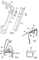
- FIG. 1 shows one half of a roof rack 1 for a passenger car, in particular a convertible or an open top with a hardtop Vehicle.
- Two lateral ones extending in the longitudinal direction of the vehicle Frame parts 2 (one is shown in FIG. 1) have foot sections 3, 4 which are used for Attach the roof rack 1 to the vehicle body.
- Integral the side frame parts 2 are support sections 5 for transverse Support elements 9 attached. These spaced apart support portions 5 are designed so that the transverse support members 9 from each other have a sufficient distance to fasten longer loads and at horizontally standing vehicle come to rest in a horizontal plane.
- the two support sections 5 are each angular and set consist of a first upright section 6 and a second transverse section 7 together, the second section 7 approximately is aligned horizontally and with its free end 8 in the direction Vehicle longitudinal median plane extends.
- the front receptacles 11 are on an upper, laterally outer Area of the windshield frame 10 attached. Like Figures 2 and 3 show, the receptacles 11 lie behind the door sealing profile 13 in one Area that is only accessible when the side vehicle door is open (Theft protection).
- the receptacles 11 consist of screw fastenings 15 impressions 14 on the A-pillar 16. Each screw fastening 15 comprises two weld nuts 21 held in position in the impression 14, into which Fastening screws 22 are screwed in.
- This connecting part 18 can be integral on the side frame part 2 cast, but also be formed separately.
- Fig. 4 shows a rear, each formed on the rear side parts 19 Recording 12 for the rear foot portion 4 of a side frame part 2 of the Roof rack 1.
- the rear side part 19 has a local depression 20 and two in the area of Recess 20 attached weld nuts 21 (one shown).
- weld nuts 21 are screws 22 that have a conical screw head 23 have turned.
- the rear foot sections 4 are comparable to the front foot sections 3 Can be fixed to the body using connecting parts using screws.
- the Connecting parts can in turn be integral on the side frame part 2 cast on, or also be formed separately.
- the receptacle 12 is supported by a roof carrier 1 not installed Slider 24, which with the conical head portions 23 of the screws 22nd cooperates, covered.
- the slider 24 is comparable to the filler 17th only when the side vehicle door is open in the vehicle's longitudinal direction into one Release position movable and then removable (anti-theft protection).
- Rear Foot section 4 of the roof rack 1 is either by the screws 22 or can be fixed by differently shaped screws on the receptacle 12
- the cross-sectional profile of the side frame parts 2 is in accordance with the Load of the roof rack 1 designed forces; it is expanding from the windshield frame 9 continuously towards the rear and has one curved course.
- the curved course is rough for optical reasons adapted to the course of the adjacent edge area of the door window pane.
- the side frame parts 2 are made of a light metal alloy (Mg, Al Alloy) and have a relatively thin wall thickness (approx. 3mm to 4mm).
- the transverse support elements 9 fastened to the support sections 5 of the side frame parts 2 consist of hollow extruded profiles (see FIG. 5), which has a receiving groove 25 for commercially available special holders, such as for roof boxes, skis, bicycles, surfboards, etc.
- the extruded profiles are closed at their lateral ends by inserted cover elements 26 and can be locked (theft protection).
Landscapes
- Engineering & Computer Science (AREA)
- Mechanical Engineering (AREA)
- Body Structure For Vehicles (AREA)
- Fittings On The Vehicle Exterior For Carrying Loads, And Devices For Holding Or Mounting Articles (AREA)
Description
Die Erfindung betrifft einen Dachlastträger an einem Personenkraftwagen, insbesondere Cabriolet, der zwei sich in Fahrzeuglängsrichtung erstreckende seitliche Rahmenteile und an diesen festgelegte, querverlaufende Tragelemente umfaßt, wobei die beiden seitlichen Rahmenteile lösbar am angrenzenden Aufbau des Personenkraftwagens in Lage gehalten sind.The invention relates to a roof rack on a passenger car, in particular Cabriolet, the two extending in the vehicle longitudinal direction lateral frame parts and transverse support elements fixed to them comprises, the two side frame parts releasably on the adjacent Structure of the passenger car are held in place.
Ein Dachlastträger der eingangs genannten Art geht aus dem deutschen Gebrauchsmuster G 87 14 471.9 hervor. Dieses beschreibt einen Dachlastträger für Cabriolets, der aus zwei mit Abstand voneinender angeordneten Längsträgerstreben sowie an diesen festgelegten Querträgerstreben besteht. Diese Längsträgerstreben sind einerseits an der A-Säule und andererseits an der B-Säule bzw. dem Überrollbügel befestigt.A roof rack of the type mentioned comes from the German Utility model G 87 14 471.9. This describes a roof rack for convertibles that consist of two spaced from each other Longitudinal struts and crossmember struts fixed on these. These longitudinal beam struts are on the one hand on the A-pillar and on the other hand on the B-pillar or the roll bar attached.
Aus der DE-OS 37 39 364 ist ein Dachlastträger für ein Cabriolet bekannt, dessen rückwärtige Füße zur Abstützung am Fahrzeug in der Fuge des Kofferraumdeckels und dessen vordere Füße zur Abstützung am Dachrahmen im Bereich der A-Säule oder in der Fuge der Motorhaube festgelegt sind.From DE-OS 37 39 364 a roof rack for a convertible is known, whose rear feet for support on the vehicle in the joint of the Trunk lid and its front feet for support on the roof frame in the Area of the A-pillar or in the joint of the bonnet.
Die Dachlastträger beider Schriften sind aus runden bzw. rechteckigen Hohlprofilen zusammengesetzt und als Schwenkdachträger ausgebildet, um ein Zurück- und Vorklappen des Faltverdecks bei aufgesetztem Dachlasttrager zu ermöglichen.The roof rack of both fonts are made of round or rectangular Hollow sections assembled and designed as a pivoting roof support to a Fold the folding top back and forth with the roof load carrier attached enable.
Nachteilig an diesen bekannten Dachlastträgern ist, daß durch deren Herstellung aus runden bzw. rechteckigen Hohlprofilen aufwendige Schweiß- und Nietverbindungen oder zusätzliche Verbindungselemente erforderlich sind, die sowohl die Verwindungssteifigkeit als auch die maximale Tragkraft des Dachlastträgers mindern.A disadvantage of these known roof rack is that by their manufacture from round or rectangular hollow profiles complex welding and Riveted joints or additional fasteners are required both the torsional stiffness and the maximum load capacity of the Reduce the roof rack.
Ferner limitiert die Verwendung von runden bzw. recht eckigen Hohlprofilen eine freie Gestaltungsmöglichkeit und eine Herstellung schwieriger Formen, so daß eine optimale Anpassung des Dachlastträgers an das Fahrzeugstyling erheblich eingeschränkt ist.Furthermore, the use of round or rectangular hollow profiles limits one free design options and a production of difficult shapes, so that an optimal adaptation of the roof rack to the vehicle styling considerably is restricted.
Aufgabe der Erfindung ist es, einen Dachlastträger der eingangs genannten Art so weiterzubilden, daß die aufgeführten Nachteile vermieden werden, die für das Fahrzeug maximal mögliche und zulässige Dachlast aufnehmbar ist und der Dachlastträger so ausgeführt werden kann, daß das optische Aussehen des Fahrzeuges bei aufgesetztem Dachlastträger positiv beeinflußt wird.The object of the invention is to provide a roof rack of the type mentioned so that the disadvantages listed are avoided, which for the Vehicle maximum possible and permissible roof load can be absorbed and the Roof rack can be designed so that the visual appearance of the Vehicle is positively influenced with the roof rack attached.
Erfindungsgemäß wird diese Aufgabe durch die kennzeichnenden Merkmale des Patentanspruchs 1 gelöst. Weitere, die Erfindung in vorteilhafter Weise ausgestaltende Merkmale enthalten die Unteransprüche.According to the invention, this object is achieved by the characterizing features of Claim 1 solved. Further, the invention advantageously design features contain the subclaims.
Die mit der Erfindung hauptsächlich erzielten Vorteile sind darin zu sehen, daß die seitlichen Rahmenteile des Dachlastträgers einteilig aus Druckguß gefertigt werden.The main advantages achieved with the invention are that the side frame parts of the roof rack are made in one piece from die-cast will.
Die Herstellung der seitlichen Rahmenteile aus Druckguß ermöglicht eine Auslegung des Rahmenprofils entsprechend den örtlichen mechanischen Anforderungen.The production of the side frame parts from die-casting enables one Design of the frame profile according to the local mechanical Conditions.
Die seitlichen Rahmenteile sind einstückig mit Fußabschnitten zur Befestigung am Fahrzeug und Stützabschnitten zur Befestigung der querverlaufenden Tragelemente ausgeführt.The side frame parts are in one piece with foot sections for fastening on the vehicle and support sections for fastening the transverse Carrying elements executed.
Ein zur Fahrzeuglängsmittelebene offenes Hohlprofil aus einer Leichtmetallegierung (Al/Mg) ermöglicht eine Gestaltung der seitlichen Rahmenteile derart, daß bei einem gefälligen Aussehen und geringem Gewicht die erforderliche mechanische Festigkeit erreicht wird.A hollow profile open to the median longitudinal plane of a Light metal alloy (Al / Mg) allows the design of the side Frame parts so that with a pleasing appearance and light weight the required mechanical strength is achieved.
Die Fertigung aus Druckguß ermöglicht ferner, die seitlichen Rahmenteile stilistisch derart zu gestalten, daß das optische Aussehen des Fahrzeuges bei aufgesetztem Dachlastträger positiv beeinflußt wird. Die seitlichen Rahmenteile folgen in gleichmäßigem Abstand der Fahrzeugkontur, wodurch sich eine gedrungene Bauform ergibt.The die-cast fabrication also enables the side frame parts stylistically in such a way that the visual appearance of the vehicle mounted roof rack is positively influenced. The side frame parts follow the vehicle contour at an even distance, resulting in a compact design results.
Die Befestigung des Dachlastträgers am Personenkraftwagen erfolgt über speziell ausgebildete Aufnahmen jeweils an beiden Fahrzeugseiten am oberen Ende des Windschutzscheibenrahmens (A-Säule) und an der Oberseite des Fondseitenteils, an denen, zu den Aufnahmen passende, an den Fußenden der seitlichen Rahmenteile angebrachte Halteelemente befestigt werden.The roof rack is attached to the passenger car via specially designed recordings on both sides of the vehicle at the top End of the windshield frame (A pillar) and at the top of the Part of the rear side, on those that match the pictures, on the foot ends of the lateral frame parts attached retaining elements are attached.
Ein Ausführungsbeispiel der Erfindung ist in der Zeichnung dargestellt und wird im folgenden näher beschrieben.An embodiment of the invention is shown in the drawing and will described in more detail below.
Es zeigt
Figur 1 zeigt eine Hälfte eines Dachlastträgers 1 für einen Personenkraftwagen,
insbesondere ein Cabriolet oder ein mit einem Hardtop versehenes offenes
Fahrzeug. Zwei sich in Fahrzeuglängsrichtung erstreckende seitliche
Rahmenteile 2 (in Fig.1 ist eines gezeigt) weisen Fußabschnitte 3, 4 auf, die zur
Befestigung des Dachlastträgers 1 an der Fahrzeugkarosserie dienen. Integral an
den seitlichen Rahmenteilen 2 sind Stützabschnitte 5 für querverlaufende
Tragelemente 9 angebracht. Diese voneinender beabstandeten Stützabschnitte 5
sind so ausgebildet, daß die querverlaufenden Tragelemente 9 voneinander
einen ausreichenden Abstand zur Befestigung längerer Lasten aufweisen und bei
waagrecht stehendem Fahrzeug in einer waagrechten Ebene zu liegen kommen.FIG. 1 shows one half of a roof rack 1 for a passenger car,
in particular a convertible or an open top with a hardtop
Vehicle. Two lateral ones extending in the longitudinal direction of the vehicle
Frame parts 2 (one is shown in FIG. 1) have foot sections 3, 4 which are used for
Attach the roof rack 1 to the vehicle body. Integral
the
Die beiden Stützabschnitte 5 sind jeweils winkelförmig ausgebildet und setzen
sich aus einem ersten aufrecht verlaufenden Abschnitt 6 und einem zweiten
querverlaufenden Abschnitt 7 zusammen, wobei der zweite Abschnitt 7 etwa
horizontal ausgerichtet ist und sich mit seinem freien Ende 8 in Richtung
Fahrzeuglängsmittelebene erstreckt.The two
Zur Befestigung des Dachlastträgers 1 am Fahrzeug weist dieses vordere und
hintere Aufnahmen 11, 12 auf, an denen die vorderen und hinteren
Fußabschnitte 3,4 des Dachlastträgers 1 befestigbar sind.To attach the roof rack 1 to the vehicle, this front and
Die vorderen Aufnahmen 11 sind an einem oberen, seitlich außenliegenden
Bereich des Windschutzscheibenrahmens 10 angebracht. Wie die Figuren 2 und
3 zeigen, liegen die Aufnahmen 11 hinter dem Türdichtungsprofil 13 in einem
Bereich, der nur bei geöffneter seitlicher Fahrzeugtüre zugänglich ist
(Diebstahlschutz). Die Aufnahmen 11 bestehen aus mit Schraubbefestigungen 15
versehenen Einprägungen 14 an der A-Säule 16. Jede Schraubbefestigung 15
umfaßt zwei in der Einprägung 14 in Lage gehaltene Schweißmuttern 21, in die
Befestigungsschrauben 22 eingedreht sind.The
Bei nicht aufgesetztem Dachlastträger 1 wird, um ein Einfallen des
Dichtungsprofils 13 im Bereich der Einprägung 14 zu verhindern, ein Füllstück 17
in die Einprägung 14 eingesetzt, das vor der Montage des Dachlastträgers 1
entfernt wird.When the roof rack 1 is not attached, to prevent the
To prevent
Bei der Montage des Dachlastträgers 1 wird, nach Entfernung des Füllstücks 17,
mittels der Schraubbefestigung 15 ein am vorderen Fußabschnitt 3 des
Dachlastträgers 1 angebrachtes Verbindungsteil 18 an der A-Säule 16
festgeschraubt. Dieses Verbindungsteil 18 kann integral am seitlichen Rahmenteil
2 angegossen, aber auch separat ausgebildet sein.When installing the roof rack 1, after removing the
Mittels der Befestigungsschrauben 22 wird entweder das Füllstück 17 oder der
vordere Fußabschnitt 3 des Dachlastträgers 1 an der A-Säule 16 des
Windschutzscheibenrahmens 10 in Lage gehalten. By means of the
Fig. 4 zeigt eine hintere, jeweils an den Fondseitenteilen 19 ausgebildete
Aufnahme 12 für den hinteren Fußabschnitt 4 eines seitlichen Rahmenteils 2 des
Dachlastträgers 1.Fig. 4 shows a rear, each formed on the
Das Fondseitenteil 19 weist eine örtliche Vertiefung 20 und zwei im Bereich der
Vertiefung 20 befestigte Schweißmuttern 21 (eine gezeigt) auf. In die
Schweißmuttern 21 sind Schrauben 22, die einen konischen Schraubenkopf 23
aufweisen, eingedreht.The
Vergleichbar den vorderen Fußabschnitten 3 sind die hinteren Fußabschnitte 4
über Verbindungsteile mittels Schrauben an der Karosserie festlegbar. Die
Verbindungsteile können wiederum integrale am seitlichen Rahmenteil 2
angegossen, oder auch separat ausgebildet sein.The rear foot sections 4 are comparable to the front foot sections 3
Can be fixed to the body using connecting parts using screws. The
Connecting parts can in turn be integral on the
Die Aufnahme 12 wird bei nicht installiertem Dachlast träger 1 durch einen
Schieber 24, der mit den konischen Kopfabschnitten 23 der Schrauben 22
zusammenwirkt, abgedeckt. Der Schieber 24 ist, vergleichbar dem Füllstück 17
nur bei geöffneter seitlicher Fahrzeugtür in Fahrzeuglängsrichtung in eine
Freigabestellung bewegbar und danach entfernbar (Diebstahlschutz). Der hintere
Fußabschnitt 4 des Dachlastträgers 1 ist entweder durch die Schrauben 22 oder
durch anders geformte Schrauben an der Aufnahme 12 festsetzbarThe
Das Querschnittsprofil der seitlichen Rahmenteile 2 ist entsprechend der bei
Belastung des Dachlastträgers 1 auftretenden Kräfte ausgelegt; es erweitert sich
vom Windschutzscheibenrahmen 9 nach hinten hin kontinuierlich und weist einen
gebogenen Verlauf auf. Der gebogene Verlauf ist aus optischen Gründen in etwa
dem Verlauf des angrenzenden Randbereiches der Türfensterscheibe angepaßt.The cross-sectional profile of the
In gleicher Weise erfolgt die Auslegung und Gestaltung der vorderen und
hinteren Stützabschnitte 5, die sich nach unten hin kontinuierlich erweitern. The design and layout of the front and
Die seitlichen Rahmenteile 2 sind aus einer Leichtmetallegierung (Mg,Al
Legierung) gefertigt und weisen eine relativ dünne Wanddicke (ca. 3mm bis
4mm) auf.The
Die an den Stützabschnitten 5 der seitlichen Rahmenteile 2 befestigten
querverlaufenden Tragelemente 9 bestehen aus hohlen Strangpreßprofilen
(siehe Fig. 5), die eine Aufnahmenut 25 für handelsübliche Spezialhalter aufweist,
wie z.B. für Dachkoffer, Skier, Fahrräder, Surfbretter usw..
Die Strangpreßprofile sind an ihren seitlichen Enden durch eingesteckte
Abdeckelemente 26 verschlossen und abschließbar (Diebstahlschutz). The
The extruded profiles are closed at their lateral ends by inserted
- 11
- DachlastträgerRoof rack
- 22nd
- Rahmenteile seitlicheFrame parts lateral
- 33rd
- Fußabschnitt vorneFront foot section
- 44th
- Fußabschnitt hintenRear foot section
- 55
- StützabschnitteSupport sections
- 66
- aufrecht verlaufende erste Stützabschnitteupright first support sections
- 77
- quer verlaufende zweite Stützabschnittetransverse second support sections
- 88th
- freien Enden der querverlaufenden zweiten Stützabschnittefree ends of the transverse second support sections
- 99
- querverlaufenden Tragelementetransverse support elements
- 1010th
- WindschutzscheibenrahmenWindshield frame
- 1111
- Aufnahme WindschutzscheibenrahmenRecording windshield frame
- 1212th
- Aufnahmen FondRecordings rear
- 1313
- TürdichtungsprofilDoor sealing profile
- 1414
- EinprägungEmbossing
- 1515
- SchraubbefestigungScrew fastening
- 1616
- A-SäuleA pillar
- 1717th
- FüllstückFilling piece
- 1818th
- VerbindungsteilConnecting part
- 1919th
- Fond-SeitenteilRear side panel
- 2020th
- Vertiefungdeepening
- 2121
- SchweißmutterWelding nut
- 2222
- Schraube/BefestigungschraubeScrew / fastening screw
- 2323
- konischer Kopfabschnitt der Schraubeconical head portion of the screw
- 2424th
- SchieberSlider
- 2525th
- AufnahmenutGroove
- 2626
- AbdeckelementCover element
Claims (11)
- A roof rack on a passenger car, in particular a cabriolet, which comprises two lateral frame parts (2) extending in the longitudinal direction of the vehicle and transversely extending support members (9) secured thereto, wherein the two lateral frame parts (2) are held in position in a detachable manner on the adjacent body of the passenger car, characterized in that the lateral frame parts (2) are formed by die-cast parts of large area, wherein each lateral frame part (2) has a front and a rear support portion (5) which are integrally moulded thereon and on which the transversely extending support members (9) rest and are secured thereto.
- A roof rack according to Claim 1, characterized in that the two support portions (5) are each angled and are formed by a first vertically extending portion (6) and a second transversely extending portion (7), wherein the second portion (7) is orientated substantially horizontally and extends with the free end (8) in the direction of the longitudinal median plane of the vehicle.
- A roof rack according to Claim 1, characterized in that a front end of the lateral frame part (2) is detachably secured to a receiving means (11) of the windscreen frame (10) by way of a base portion (3) mounted on the said lateral frame part (2).
- A roof rack according to Claim 3, characterized in that the receiving means (11) provided on an A-column (16) of the windscreen frame (10) is accessible only when the side door of the vehicle is opened.
- A roof rack according to Claims 3 and 4, characterized in that when the roof rack (1) is not mounted a filler member (17) is inserted into the receiving means (11) and is removed when the roof rack (1) is assembled.
- A roof rack according to Claim 1, characterized in that a rear end of the lateral frame part (2) is detachably secured to a receiving means (12) formed on the top of the rear side part (19).
- A roof rack according to Claim 6, characterized in that the receiving means (12) formed on the rear side part (19) is covered by a slide (24) in its position of non-use, and the slide (24) is movable into a release position only when the side door of the vehicle is opened.
- A roof rack according to one or more of the preceding Claims, characterized in that the cross-section of the lateral frame part (2) is continuously widened from the windscreen frame (10) towards the rear, and the frame part (2) has a curved shape which corresponds substantially to the shape of the adjacent edge area of the window pane of the door.
- A roof rack according to Claim 2, characterized in that the first vertically extending support portion (6) of the front and rear support portions (5) is continuously widened downwards.
- A roof rack according to Claim 7, characterized in that the slide (24) cooperates in a longitudinally displaceable manner with at least one head portion (23) of a bolt (22) screwed into a weld nut (21), whereas the slide (24) is fixed by the head portion (23) in the transverse direction.
- A roof rack according to Claim 1, characterized in that the frame parts (2) are produced from a light-metal alloy (Mg, Al-alloy).
Applications Claiming Priority (2)
| Application Number | Priority Date | Filing Date | Title |
|---|---|---|---|
| DE4441410A DE4441410C1 (en) | 1994-11-12 | 1994-11-12 | Roof rack esp. for open top vehicles e.g. convertibles |
| DE4441410 | 1994-11-12 |
Publications (2)
| Publication Number | Publication Date |
|---|---|
| EP0711684A1 EP0711684A1 (en) | 1996-05-15 |
| EP0711684B1 true EP0711684B1 (en) | 1998-07-29 |
Family
ID=6533776
Family Applications (1)
| Application Number | Title | Priority Date | Filing Date |
|---|---|---|---|
| EP95115530A Expired - Lifetime EP0711684B1 (en) | 1994-11-12 | 1995-10-02 | Roof carrier |
Country Status (3)
| Country | Link |
|---|---|
| US (1) | US5676291A (en) |
| EP (1) | EP0711684B1 (en) |
| DE (2) | DE4441410C1 (en) |
Families Citing this family (7)
| Publication number | Priority date | Publication date | Assignee | Title |
|---|---|---|---|---|
| DE19746225B4 (en) * | 1997-10-21 | 2006-01-26 | Oris Fahrzeugteile Hans Riehle Gmbh | Roof rack |
| DE19948475A1 (en) * | 1999-10-08 | 2001-04-19 | Jac Products Deutschland Gmbh | Roof rails for vehicles and manufacturing processes |
| US7232170B2 (en) * | 2005-01-21 | 2007-06-19 | Magna International Inc. | Side opening cargo rack |
| DE102007032321B4 (en) * | 2007-07-11 | 2011-12-01 | Wilhelm Karmann Gmbh | Device with at least in the range of a vehicle roof of a vehicle positionable protective elements |
| US8684244B2 (en) | 2008-12-23 | 2014-04-01 | Fabio Pedrini | Vehicle-mounted equipment carrier with one-piece, fixed position frame construction |
| US10029736B1 (en) * | 2017-01-17 | 2018-07-24 | Ford Global Technologies, Llc | Roof frame including a brace reinforcing arched members |
| US11708034B2 (en) * | 2021-09-16 | 2023-07-25 | Ford Global Technologies, Llc | Modular roof rack assembly and reconfiguration method |
Family Cites Families (14)
| Publication number | Priority date | Publication date | Assignee | Title |
|---|---|---|---|---|
| DE8136800U1 (en) * | 1982-05-13 | Hagus C. Luchtenberg Gmbh & Co Kg, 5650 Solingen | Cross brace for connecting the longitudinal support rods of a roof rail of a car roof | |
| US4299346A (en) * | 1979-10-04 | 1981-11-10 | Auto Trends, Inc. | Automobile luggage rack |
| US4538752A (en) * | 1984-09-19 | 1985-09-03 | Welter Charles J | Top carrier for a convertible jeep-type vehicle |
| US4673119A (en) * | 1985-03-04 | 1987-06-16 | Bott John Anthony | Vehicle luggage carrier |
| DE3520132A1 (en) * | 1985-06-05 | 1986-12-11 | Bayerische Motoren Werke AG, 8000 München | Roof rack fastening on a soft-top coupé |
| DE3718727A1 (en) * | 1987-06-04 | 1988-12-22 | Opel Adam Ag | ROOF RACK |
| DE8714471U1 (en) * | 1987-10-30 | 1987-12-10 | Wilhelm Karmann GmbH, 4500 Osnabrück | Load carrier for convertibles |
| DE8715013U1 (en) * | 1987-11-11 | 1988-04-07 | Köll, Philipp O. | Motor vehicle roof rack |
| DE3739364A1 (en) * | 1987-11-20 | 1989-06-01 | Eckard Design Gmbh | Roofrack |
| DE4223898A1 (en) * | 1992-07-21 | 1994-01-27 | Happich Gmbh Gebr | Roof rails for vehicles |
| US5292045A (en) * | 1992-07-30 | 1994-03-08 | Mandel F Howard | Multipurpose rack for convertible top motor vehicles |
| US5273195A (en) * | 1992-10-26 | 1993-12-28 | John A. Bott | Adjustable cross rail for a vehicle article carrier |
| DE4316947A1 (en) * | 1993-05-21 | 1994-11-24 | Daimler Benz Ag | Motor vehicle with a rail for the attachment of a load carrier |
| DE4317794A1 (en) * | 1993-05-28 | 1994-12-01 | Porsche Ag | Roof rack for a passenger car |
-
1994
- 1994-11-12 DE DE4441410A patent/DE4441410C1/en not_active Expired - Fee Related
-
1995
- 1995-10-02 DE DE59502969T patent/DE59502969D1/en not_active Expired - Lifetime
- 1995-10-02 EP EP95115530A patent/EP0711684B1/en not_active Expired - Lifetime
- 1995-11-13 US US08/558,287 patent/US5676291A/en not_active Expired - Fee Related
Also Published As
| Publication number | Publication date |
|---|---|
| EP0711684A1 (en) | 1996-05-15 |
| DE59502969D1 (en) | 1998-09-03 |
| DE4441410C1 (en) | 1996-02-22 |
| US5676291A (en) | 1997-10-14 |
Similar Documents
| Publication | Publication Date | Title |
|---|---|---|
| DE19716047C2 (en) | Fastening device for roof rack | |
| DE4018593C2 (en) | Upright pillar for a vehicle body structure | |
| EP0461345B1 (en) | Body for a motor vehicle, especially for a passenger car | |
| DE102007006722C5 (en) | Carrier for a body of a motor vehicle | |
| EP0648630B1 (en) | Foldable top for convertible | |
| DE4013784C2 (en) | Car body, in particular for passenger cars | |
| DE19917177B4 (en) | Support structure for motor vehicles | |
| DE102010045586A1 (en) | Frame structure for the body floor of a motor vehicle, ground unit, substructure and vehicle body | |
| DE3929831C1 (en) | ||
| EP1036688B1 (en) | Motor vehicle, particularly passenger vehicle | |
| EP0711684B1 (en) | Roof carrier | |
| DE4342960C1 (en) | Passenger cell for a passenger car with load-bearing body structure | |
| EP0713794A1 (en) | Folding top for vehicle, particularly for passenger motorvehicle | |
| DE10218701C1 (en) | Roll over cage for motor vehicle has side legs formed of light alloy with profiled sections having cellular reinforcement | |
| DE19713317A1 (en) | Tailgate for motor vehicle | |
| DE69707522T2 (en) | Door reinforcement device for motor vehicles | |
| EP0836960B1 (en) | Convertible vehicle | |
| DE19829832B4 (en) | Body structure for a motor vehicle | |
| DE4317794A1 (en) | Roof rack for a passenger car | |
| DE602004002456T2 (en) | FRONT FOOT ARRANGEMENT IN A CAR | |
| DE4330014A1 (en) | Motor vehicle, in particular van | |
| EP0413099B1 (en) | Kit for transforming a saloon motor car into a cabriolet | |
| DE68904721T2 (en) | LUGGAGE RACK FOR MOTORHOMES AND THE LIKE. | |
| DE9416113U1 (en) | Kickstand for motor vehicles | |
| DE4316947A1 (en) | Motor vehicle with a rail for the attachment of a load carrier |
Legal Events
| Date | Code | Title | Description |
|---|---|---|---|
| PUAI | Public reference made under article 153(3) epc to a published international application that has entered the european phase |
Free format text: ORIGINAL CODE: 0009012 |
|
| AK | Designated contracting states |
Kind code of ref document: A1 Designated state(s): DE FR GB IT |
|
| 17P | Request for examination filed |
Effective date: 19961009 |
|
| GRAG | Despatch of communication of intention to grant |
Free format text: ORIGINAL CODE: EPIDOS AGRA |
|
| GRAG | Despatch of communication of intention to grant |
Free format text: ORIGINAL CODE: EPIDOS AGRA |
|
| GRAH | Despatch of communication of intention to grant a patent |
Free format text: ORIGINAL CODE: EPIDOS IGRA |
|
| ITF | It: translation for a ep patent filed | ||
| 17Q | First examination report despatched |
Effective date: 19980119 |
|
| GRAH | Despatch of communication of intention to grant a patent |
Free format text: ORIGINAL CODE: EPIDOS IGRA |
|
| GRAA | (expected) grant |
Free format text: ORIGINAL CODE: 0009210 |
|
| AK | Designated contracting states |
Kind code of ref document: B1 Designated state(s): DE FR GB IT |
|
| GBT | Gb: translation of ep patent filed (gb section 77(6)(a)/1977) |
Effective date: 19980803 |
|
| REF | Corresponds to: |
Ref document number: 59502969 Country of ref document: DE Date of ref document: 19980903 |
|
| ET | Fr: translation filed | ||
| PLBE | No opposition filed within time limit |
Free format text: ORIGINAL CODE: 0009261 |
|
| STAA | Information on the status of an ep patent application or granted ep patent |
Free format text: STATUS: NO OPPOSITION FILED WITHIN TIME LIMIT |
|
| 26N | No opposition filed | ||
| REG | Reference to a national code |
Ref country code: GB Ref legal event code: IF02 |
|
| REG | Reference to a national code |
Ref country code: FR Ref legal event code: TP |
|
| REG | Reference to a national code |
Ref country code: FR Ref legal event code: CD |
|
| PGFP | Annual fee paid to national office [announced via postgrant information from national office to epo] |
Ref country code: FR Payment date: 20101104 Year of fee payment: 16 |
|
| REG | Reference to a national code |
Ref country code: FR Ref legal event code: TP |
|
| PGFP | Annual fee paid to national office [announced via postgrant information from national office to epo] |
Ref country code: DE Payment date: 20100923 Year of fee payment: 16 |
|
| PGFP | Annual fee paid to national office [announced via postgrant information from national office to epo] |
Ref country code: GB Payment date: 20101021 Year of fee payment: 16 Ref country code: IT Payment date: 20101026 Year of fee payment: 16 |
|
| REG | Reference to a national code |
Ref country code: GB Ref legal event code: 732E Free format text: REGISTERED BETWEEN 20110310 AND 20110316 |
|
| REG | Reference to a national code |
Ref country code: GB Ref legal event code: 732E Free format text: REGISTERED BETWEEN 20110331 AND 20110406 |
|
| GBPC | Gb: european patent ceased through non-payment of renewal fee |
Effective date: 20111002 |
|
| REG | Reference to a national code |
Ref country code: FR Ref legal event code: ST Effective date: 20120629 |
|
| PG25 | Lapsed in a contracting state [announced via postgrant information from national office to epo] |
Ref country code: IT Free format text: LAPSE BECAUSE OF NON-PAYMENT OF DUE FEES Effective date: 20111002 Ref country code: GB Free format text: LAPSE BECAUSE OF NON-PAYMENT OF DUE FEES Effective date: 20111002 Ref country code: FR Free format text: LAPSE BECAUSE OF NON-PAYMENT OF DUE FEES Effective date: 20111102 |
|
| PG25 | Lapsed in a contracting state [announced via postgrant information from national office to epo] |
Ref country code: DE Free format text: LAPSE BECAUSE OF NON-PAYMENT OF DUE FEES Effective date: 20130501 |
|
| REG | Reference to a national code |
Ref country code: DE Ref legal event code: R119 Ref document number: 59502969 Country of ref document: DE Effective date: 20130501 |