EP0711219B1 - Dispositif de prehension et d'amortissement de chocs sur des outils de frappe - Google Patents
Dispositif de prehension et d'amortissement de chocs sur des outils de frappe Download PDFInfo
- Publication number
- EP0711219B1 EP0711219B1 EP95920144A EP95920144A EP0711219B1 EP 0711219 B1 EP0711219 B1 EP 0711219B1 EP 95920144 A EP95920144 A EP 95920144A EP 95920144 A EP95920144 A EP 95920144A EP 0711219 B1 EP0711219 B1 EP 0711219B1
- Authority
- EP
- European Patent Office
- Prior art keywords
- tool
- sleeve tube
- sleeve
- plastic
- gripping
- Prior art date
- Legal status (The legal status is an assumption and is not a legal conclusion. Google has not performed a legal analysis and makes no representation as to the accuracy of the status listed.)
- Expired - Lifetime
Links
- 230000035939 shock Effects 0.000 title description 2
- 230000006835 compression Effects 0.000 claims description 4
- 238000007906 compression Methods 0.000 claims description 4
- 239000010438 granite Substances 0.000 claims description 2
- 238000009527 percussion Methods 0.000 claims 2
- 239000004744 fabric Substances 0.000 claims 1
- 230000001681 protective effect Effects 0.000 claims 1
- 238000004026 adhesive bonding Methods 0.000 description 2
- 235000020303 café frappé Nutrition 0.000 description 2
- 239000000463 material Substances 0.000 description 2
- 238000010521 absorption reaction Methods 0.000 description 1
- 239000011248 coating agent Substances 0.000 description 1
- 238000000576 coating method Methods 0.000 description 1
- 230000000295 complement effect Effects 0.000 description 1
- 230000000694 effects Effects 0.000 description 1
- 230000002093 peripheral effect Effects 0.000 description 1
- 238000002791 soaking Methods 0.000 description 1
Images

Classifications
-
- B—PERFORMING OPERATIONS; TRANSPORTING
- B25—HAND TOOLS; PORTABLE POWER-DRIVEN TOOLS; MANIPULATORS
- B25D—PERCUSSIVE TOOLS
- B25D3/00—Hand chisels
-
- B—PERFORMING OPERATIONS; TRANSPORTING
- B25—HAND TOOLS; PORTABLE POWER-DRIVEN TOOLS; MANIPULATORS
- B25G—HANDLES FOR HAND IMPLEMENTS
- B25G1/00—Handle constructions
- B25G1/01—Shock-absorbing means
-
- Y—GENERAL TAGGING OF NEW TECHNOLOGICAL DEVELOPMENTS; GENERAL TAGGING OF CROSS-SECTIONAL TECHNOLOGIES SPANNING OVER SEVERAL SECTIONS OF THE IPC; TECHNICAL SUBJECTS COVERED BY FORMER USPC CROSS-REFERENCE ART COLLECTIONS [XRACs] AND DIGESTS
- Y10—TECHNICAL SUBJECTS COVERED BY FORMER USPC
- Y10S—TECHNICAL SUBJECTS COVERED BY FORMER USPC CROSS-REFERENCE ART COLLECTIONS [XRACs] AND DIGESTS
- Y10S16/00—Miscellaneous hardware, e.g. bushing, carpet fastener, caster, door closer, panel hanger, attachable or adjunct handle, hinge, window sash balance
- Y10S16/12—Hand grips, preformed and semi-permanent
Definitions
- the invention relates to the technical sector of tooling and in particular tools to strike such as in particular pin punch.
- guards carried out in the form of a flange or cup having a central opening allowing tool engagement and attaching to it with lips likely to engage in a flange or groove circular formed on the tool body. This type of guard has for function only to protect the hand of the user.
- the aim sought after according to the invention was therefore to design a new device which allows a good grip of the tool, and which absorbs vibrations due to the forces of aforementioned strikes.
- Another goal was to design a device simple, low cost and which can be adapted to any section of the tool body.
- the device for grip adapting to striking tools of the type comprising a plastic sleeve engaging on the body of the tool is remarkable in that it includes a plastic sleeve having flexibility in its structure, and comprising a plurality of ring shapes, of large diameter, interconnected by forms of connection of smaller section by defining a bellows structure and undulations, and in that, at the place of each connection between the rings, is provided a circular inner projection bearing against the body of the tool, and in that the sleeve has at least an inner collar capable of engaging and clipping to the interior of at least one circular groove formed in the tool body.
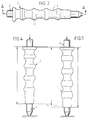
- the device according to the invention is designed and produced under the shape of a plastic sleeve (1) having a flexibility in its structure to allow its deformation.
- This sleeve is established over a long length and it includes the along it a plurality of ring shapes (1.1) of large diameter interconnected by connecting forms (1.2) of smaller section, the assembly defining a bellows structure with undulations.
- an internal projection circular (1.3) capable of coming to bear against the body of the tool.
- an inner collar (1.4) which is likely to come engage and clip inside at least one groove circular (2.1) formed in the body (2) of the tool. This flange forming lip is clipped into the groove in thus ensuring perfect holding of the device.
- the device according to the invention by its structure and its forms, by the bellows effect the absorption of shocks due to impact forces causing the deformation of the sleeve either by elongation or by compression, and by sliding on the tool body.
- the sleeve has a guard shape in its head part protection of the user's hand, having a cross-section diametral suitable for ensuring such a function.
- said head may have a complementary connection zone with the front part of the striking tool, opposite its zone useful contact with the part to be struck.
- the sleeve can have all or part of its length a granite coating obtained by soaking in a bath appropriate.
- the sleeve according to the invention can be applied to any tool striking, such as pin punch or other, chisel or other, and be of all sections in diameter and length.
Landscapes
- Engineering & Computer Science (AREA)
- Mechanical Engineering (AREA)
- Percussive Tools And Related Accessories (AREA)
- Treatment Of Fiber Materials (AREA)
Description
Claims (6)
- Dispositif de préhension s'adaptant sur des outils de frappe du type comprenant un manchon en matière plastique s'engageant sur le corps de l'outil, caractérisé en ce qu'il comprend un manchon (1) en matière plastique présentant une souplesse dans sa structure, et comprenant une pluralité de formes en anneaux (1.1), de grand diamètre, reliées entre elles par des formes de liaison (1.2) de section plus réduite en définissant une structure en soufflet et ondulations,
et en ce que, à l'endroit de chaque liaison entre les anneaux, est prévue une saillie intérieure circulaire (1.3) venant en appui contre le corps de l'outil,
et en ce que le manchon présente au moins une collerette intérieure (1.4) susceptible de s'engager et se clipser à l'intérieur d'au moins une rainure circulaire (2.1) formée dans le corps de l'outil. - Dispositif selon la revendication 1, caractérisé en ce que le manchon présente en prolongement une forme en tête constituant une garde de protection.
- Dispositif selon la revendication 1, caractérisé en ce que la partie en soufflet dudit manchon est déformable en allongement ou compression, et coulisse le long du corps de l'outil de frappe.
- Dispositif selon la revendication 3, caractérisé en ce que les saillies intérieures circulaires (1.3) sont établies d'une certaine épaisseur supérieure à la profondeur des zones de liaison (1.2) et de raccordement entre elles qui n'ont pas de contact avec le corps de l'outil.
- Dispositif selon la revendication 1, caractérisé en ce que le manchon présente sur tout ou partie de sa longueur, un revêtement granité.
- Dispositif selon la revendication 2, caractérisé en ce que le prolongement du manchon formant tête présente une zone d'ancrage complémentaire sur le corps de l'outil.
Applications Claiming Priority (3)
| Application Number | Priority Date | Filing Date | Title |
|---|---|---|---|
| FR9406639 | 1994-05-24 | ||
| FR9406639A FR2720314B1 (fr) | 1994-05-24 | 1994-05-24 | Dispositif de préhension et d'amortissement de chocs sur des outils de frappe. |
| PCT/FR1995/000630 WO1995032077A1 (fr) | 1994-05-24 | 1995-05-16 | Dispositif de prehension et d'amortissement de chocs sur des outils de frappe |
Publications (2)
| Publication Number | Publication Date |
|---|---|
| EP0711219A1 EP0711219A1 (fr) | 1996-05-15 |
| EP0711219B1 true EP0711219B1 (fr) | 1999-01-13 |
Family
ID=9463714
Family Applications (1)
| Application Number | Title | Priority Date | Filing Date |
|---|---|---|---|
| EP95920144A Expired - Lifetime EP0711219B1 (fr) | 1994-05-24 | 1995-05-16 | Dispositif de prehension et d'amortissement de chocs sur des outils de frappe |
Country Status (8)
| Country | Link |
|---|---|
| US (1) | US5730231A (fr) |
| EP (1) | EP0711219B1 (fr) |
| JP (1) | JP3522282B2 (fr) |
| AU (1) | AU2571295A (fr) |
| DE (1) | DE69507262T2 (fr) |
| ES (1) | ES2126281T3 (fr) |
| FR (1) | FR2720314B1 (fr) |
| WO (1) | WO1995032077A1 (fr) |
Cited By (1)
| Publication number | Priority date | Publication date | Assignee | Title |
|---|---|---|---|---|
| US6948647B1 (en) | 2004-05-25 | 2005-09-27 | Black & Decker Inc. | Anti-slip shingle grip for fastening tool |
Families Citing this family (26)
| Publication number | Priority date | Publication date | Assignee | Title |
|---|---|---|---|---|
| FR2743321B1 (fr) * | 1996-01-05 | 1998-02-13 | Soc D Expl Des Ets Racodon Sa | Poignee pour outils de frappe a main |
| USD423891S (en) | 1998-02-11 | 2000-05-02 | Snap-On Tools Company | Ratchet |
| USD413238S (en) | 1998-07-06 | 1999-08-31 | Maxtech Manufacturing Inc. | Striking tool |
| DE10005366A1 (de) | 2000-02-07 | 2001-08-09 | Hilti Ag | Werkzeughalter |
| US6405619B1 (en) * | 2001-03-23 | 2002-06-18 | Wki Holding Company, Inc. | Self-securing tool handle |
| DE20213112U1 (de) * | 2002-08-21 | 2004-02-12 | Weha - Ludwig Werwein Gmbh | Meißel |
| US20050028653A1 (en) * | 2003-08-08 | 2005-02-10 | Chih-Ching Hsien | Hand tool having an adjustable holding portion |
| FR2859936A1 (fr) * | 2003-09-22 | 2005-03-25 | Gb Metallurg | Outil tel que burin, pointerolle pourvu d'un dispositif de protection |
| US7624893B2 (en) * | 2006-03-28 | 2009-12-01 | Access Business Group International Llc | Cookware handle with metal insert and overmold |
| FR2919514B1 (fr) * | 2007-07-30 | 2009-11-13 | Remy Racodon | Poignee pour outils de frappe a main. |
| GB0822571D0 (en) * | 2008-12-11 | 2009-01-14 | Houghton Benjamin A | Improved handle |
| IT1394729B1 (it) * | 2009-07-08 | 2012-07-13 | Delfino | Utensile manuale per materiale lapideo e mazzetta per tale utensile |
| FR2956830B1 (fr) | 2010-02-26 | 2012-04-06 | Bruno Racodon | Poignee pour outils de frappe a main |
| US20120211020A1 (en) * | 2011-02-22 | 2012-08-23 | Julius Garcia | Helical hair tie |
| US20120324666A1 (en) * | 2011-06-27 | 2012-12-27 | Leigh-Anna Provenzano | Grip for hair styling device |
| US8465384B2 (en) * | 2011-09-15 | 2013-06-18 | Ben D. Blosser | Fletching sleeve system and method of application and manufacture |
| DE102012202300A1 (de) * | 2012-02-15 | 2013-08-22 | Hilti Aktiengesellschaft | Meißel |
| US9700703B2 (en) * | 2013-02-26 | 2017-07-11 | Coeur, Inc. | Guidewire insertion tool |
| USD755528S1 (en) * | 2013-03-08 | 2016-05-10 | Leigh-Anna Provenzano | Grip for hair styling device |
| KR101533598B1 (ko) * | 2013-12-05 | 2015-07-03 | (주)삼미통상 | 안정성과 열효율이 향상된 이중조리용기 |
| KR101563547B1 (ko) | 2014-01-27 | 2015-11-06 | 문경선 | 가변형 핸드 그립 |
| TWI468268B (zh) * | 2014-05-02 | 2015-01-11 | Centrifuge Ind Co Ltd | 適用敲擊工具用之衝擊件之連接桿 |
| US9630311B2 (en) * | 2014-12-23 | 2017-04-25 | Charlie Creelman | Pistol grip attachment for use with a paintbrush |
| US11234899B2 (en) * | 2017-05-11 | 2022-02-01 | Scalpal Llc | Grasping facilitators and uses thereof and kits involving the same |
| KR101834784B1 (ko) * | 2016-05-20 | 2018-04-19 | (주)에스엠허스 | 의료용 튜브 홀더 |
| US11937862B2 (en) * | 2019-01-18 | 2024-03-26 | Shukla Medical | Striking assembly and surgical tool assembly |
Family Cites Families (16)
| Publication number | Priority date | Publication date | Assignee | Title |
|---|---|---|---|---|
| US811390A (en) * | 1905-04-26 | 1906-01-30 | Samuel E Foreman | Tool-handle. |
| US2144474A (en) * | 1936-09-23 | 1939-01-17 | Westinghouse Electric & Mfg Co | Ventilated handle for sadirons |
| US2231222A (en) * | 1939-06-26 | 1941-02-11 | Kewaskum Aluminum Company | Handle for cooking utensils |
| US2278707A (en) * | 1941-12-11 | 1942-04-07 | Diamond Expansion Bolt Co | Safety percussion drill holder and article |
| US3072955A (en) * | 1959-05-18 | 1963-01-15 | Lois D Mitchell | Hand grips |
| US3163865A (en) * | 1961-09-13 | 1965-01-05 | Port Clinton Mfg Company | Drive tool |
| US3302673A (en) * | 1965-02-08 | 1967-02-07 | Harold S Forsberg | Composite tool handle |
| FR2106726A5 (fr) * | 1970-09-22 | 1972-05-05 | Ern Gustav Emil | |
| DE2610663C3 (de) * | 1976-03-13 | 1978-08-24 | Carl Dan. Peddinghaus Kg, 5828 Ennepetal | Handgriff zur Aufnahme eines Werkzeugschaftes |
| DE2657448C3 (de) * | 1976-12-15 | 1980-11-20 | C. Friedr. Tillmanns Kg, 5630 Remscheid | Handschutz |
| FR2431352A1 (fr) * | 1978-07-20 | 1980-02-15 | Brunon Louis | Garde pour outil de frappe a main |
| US4197611A (en) * | 1978-09-14 | 1980-04-15 | Lincoln Manufacturing Company, Inc. | Hand grip for cooking utensil handle |
| GB8531885D0 (en) * | 1985-12-30 | 1986-02-05 | Fox J K Snr | Tool |
| US4890355A (en) * | 1988-10-26 | 1990-01-02 | Schulten Elizabeth W | Releasably mountable hand grip for handles |
| DE9307623U1 (de) * | 1993-05-19 | 1993-09-30 | J. König GmbH & Co Werkzeugfabrik, Steinindustrie- und Handwerkerbedarf, 76227 Karlsruhe | Schrifthammer sowie Schutzhülse für diesen |
| DE9308665U1 (de) * | 1993-06-09 | 1993-08-05 | Ching, Peing Jung, Taichung | Schlägergriff |
-
1994
- 1994-05-24 FR FR9406639A patent/FR2720314B1/fr not_active Expired - Lifetime
-
1995
- 1995-05-16 AU AU25712/95A patent/AU2571295A/en not_active Abandoned
- 1995-05-16 DE DE69507262T patent/DE69507262T2/de not_active Expired - Lifetime
- 1995-05-16 US US08/586,850 patent/US5730231A/en not_active Expired - Lifetime
- 1995-05-16 JP JP53009295A patent/JP3522282B2/ja not_active Expired - Fee Related
- 1995-05-16 ES ES95920144T patent/ES2126281T3/es not_active Expired - Lifetime
- 1995-05-16 EP EP95920144A patent/EP0711219B1/fr not_active Expired - Lifetime
- 1995-05-16 WO PCT/FR1995/000630 patent/WO1995032077A1/fr not_active Ceased
Cited By (2)
| Publication number | Priority date | Publication date | Assignee | Title |
|---|---|---|---|---|
| US6948647B1 (en) | 2004-05-25 | 2005-09-27 | Black & Decker Inc. | Anti-slip shingle grip for fastening tool |
| US7210607B2 (en) | 2004-05-25 | 2007-05-01 | Black & Decker Inc. | Anti-slip shingle grip for fastening tool |
Also Published As
| Publication number | Publication date |
|---|---|
| DE69507262T2 (de) | 1999-05-27 |
| WO1995032077A1 (fr) | 1995-11-30 |
| JP3522282B2 (ja) | 2004-04-26 |
| DE69507262D1 (de) | 1999-02-25 |
| JPH10508257A (ja) | 1998-08-18 |
| FR2720314A1 (fr) | 1995-12-01 |
| ES2126281T3 (es) | 1999-03-16 |
| FR2720314B1 (fr) | 1996-07-05 |
| US5730231A (en) | 1998-03-24 |
| AU2571295A (en) | 1995-12-18 |
| EP0711219A1 (fr) | 1996-05-15 |
Similar Documents
| Publication | Publication Date | Title |
|---|---|---|
| EP0711219B1 (fr) | Dispositif de prehension et d'amortissement de chocs sur des outils de frappe | |
| FR2473392A1 (fr) | Poignee, notamment pour outils portatifs | |
| EP0173607B2 (fr) | Roulement à aiguilles, notamment douille à aiguilles à étanchéité renforcée | |
| EP1419837A1 (fr) | Mandrin porte-outil à système de verrouillage | |
| FR2798707A1 (fr) | Dispositif d'arret d'une piece sur un boulon | |
| FR2864461A1 (fr) | Tube de poignee d'un outil de travail guide et manoeuvre a la main | |
| FR2869376A1 (fr) | Dispositif de transmission de puissance | |
| FR2981290A3 (fr) | Dispositif de serrage | |
| FR2523238A1 (fr) | Dispositif de protection d'arbre de transmission | |
| FR2676697A1 (fr) | Colonne de direction de vehicule reglable en longueur. | |
| EP0465288A1 (fr) | Dispositif de fixation de plaques de revêtement sur un support et assemblage obtenu à l'aide de ce dispositif | |
| FR3000760A1 (fr) | Rame de liaison entre le verrou et la serrure d'un ouvrant de vehicule automobile, comportant une piece de protection anti-vol | |
| FR2857761A1 (fr) | Organe de pre-maintien de pedalier. | |
| FR2479378A1 (fr) | Dispositif de debrayage, notamment pour des embrayages de vehicules automobiles | |
| FR2650642A1 (fr) | Organe de maintien et de fixation d'isolant sur des surfaces diverses | |
| EP2020278B1 (fr) | Poignée pour outils de frappe à main | |
| FR2494613A1 (fr) | Procede et dispositif d'assemblage non demontable de pieces tournantes, telles que des elements d'arbre | |
| FR2737257A1 (fr) | Silencieux place dans un tuyau | |
| WO2021078747A1 (fr) | Outillage d'insertion par interférence dans une structure d'une fixation et méthode d'installation par interférence dans une structure d'une fixation au moyen d'un tel outillage | |
| FR2537672A1 (fr) | Appareil de fixation aveugle et assemblage comportant un tel appareil | |
| FR2825762A1 (fr) | Dispositif de fixation a rivet et application | |
| CH271547A (fr) | Poignée pour guidons de cycles et motocycles. | |
| CH477335A (fr) | Dispositif de protection d'un bord biseauté de tuyau | |
| EP0592271B1 (fr) | Dispositif d'isolation acoustique, notamment pour tablier avant de véhicule automobile | |
| EP0761985A1 (fr) | Dispositif de fixation à au moins deux degrés de liberté et son application notamment aux véhicules automobiles terrestres |
Legal Events
| Date | Code | Title | Description |
|---|---|---|---|
| PUAI | Public reference made under article 153(3) epc to a published international application that has entered the european phase |
Free format text: ORIGINAL CODE: 0009012 |
|
| AK | Designated contracting states |
Kind code of ref document: A1 Designated state(s): DE ES GB IT SE |
|
| 17P | Request for examination filed |
Effective date: 19960514 |
|
| 17Q | First examination report despatched |
Effective date: 19970421 |
|
| GRAG | Despatch of communication of intention to grant |
Free format text: ORIGINAL CODE: EPIDOS AGRA |
|
| GRAG | Despatch of communication of intention to grant |
Free format text: ORIGINAL CODE: EPIDOS AGRA |
|
| GRAH | Despatch of communication of intention to grant a patent |
Free format text: ORIGINAL CODE: EPIDOS IGRA |
|
| GRAH | Despatch of communication of intention to grant a patent |
Free format text: ORIGINAL CODE: EPIDOS IGRA |
|
| GRAA | (expected) grant |
Free format text: ORIGINAL CODE: 0009210 |
|
| AK | Designated contracting states |
Kind code of ref document: B1 Designated state(s): DE ES GB IT SE |
|
| PG25 | Lapsed in a contracting state [announced via postgrant information from national office to epo] |
Ref country code: SE Free format text: THE PATENT HAS BEEN ANNULLED BY A DECISION OF A NATIONAL AUTHORITY Effective date: 19990113 |
|
| GBT | Gb: translation of ep patent filed (gb section 77(6)(a)/1977) |
Effective date: 19990113 |
|
| ITF | It: translation for a ep patent filed | ||
| REF | Corresponds to: |
Ref document number: 69507262 Country of ref document: DE Date of ref document: 19990225 |
|
| REG | Reference to a national code |
Ref country code: ES Ref legal event code: FG2A Ref document number: 2126281 Country of ref document: ES Kind code of ref document: T3 |
|
| PLBE | No opposition filed within time limit |
Free format text: ORIGINAL CODE: 0009261 |
|
| STAA | Information on the status of an ep patent application or granted ep patent |
Free format text: STATUS: NO OPPOSITION FILED WITHIN TIME LIMIT |
|
| 26N | No opposition filed | ||
| REG | Reference to a national code |
Ref country code: GB Ref legal event code: IF02 |
|
| PGFP | Annual fee paid to national office [announced via postgrant information from national office to epo] |
Ref country code: GB Payment date: 20140520 Year of fee payment: 20 |
|
| PGFP | Annual fee paid to national office [announced via postgrant information from national office to epo] |
Ref country code: IT Payment date: 20140513 Year of fee payment: 20 Ref country code: ES Payment date: 20140520 Year of fee payment: 20 Ref country code: DE Payment date: 20140509 Year of fee payment: 20 |
|
| REG | Reference to a national code |
Ref country code: DE Ref legal event code: R071 Ref document number: 69507262 Country of ref document: DE |
|
| REG | Reference to a national code |
Ref country code: DE Ref legal event code: R071 Ref document number: 69507262 Country of ref document: DE |
|
| REG | Reference to a national code |
Ref country code: GB Ref legal event code: PE20 Expiry date: 20150515 |
|
| PG25 | Lapsed in a contracting state [announced via postgrant information from national office to epo] |
Ref country code: GB Free format text: LAPSE BECAUSE OF EXPIRATION OF PROTECTION Effective date: 20150515 |
|
| REG | Reference to a national code |
Ref country code: ES Ref legal event code: FD2A Effective date: 20150826 |
|
| PG25 | Lapsed in a contracting state [announced via postgrant information from national office to epo] |
Ref country code: ES Free format text: LAPSE BECAUSE OF EXPIRATION OF PROTECTION Effective date: 20150517 |