EP0709978A2 - Système optique de transmission pour des signaux de télévision par câble et pour des signaux d'abonnés individuels - Google Patents
Système optique de transmission pour des signaux de télévision par câble et pour des signaux d'abonnés individuels Download PDFInfo
- Publication number
- EP0709978A2 EP0709978A2 EP95117135A EP95117135A EP0709978A2 EP 0709978 A2 EP0709978 A2 EP 0709978A2 EP 95117135 A EP95117135 A EP 95117135A EP 95117135 A EP95117135 A EP 95117135A EP 0709978 A2 EP0709978 A2 EP 0709978A2
- Authority
- EP
- European Patent Office
- Prior art keywords
- electrical
- signal
- optical
- frequency
- mux
- Prior art date
- Legal status (The legal status is an assumption and is not a legal conclusion. Google has not performed a legal analysis and makes no representation as to the accuracy of the status listed.)
- Granted
Links
Images


Classifications
-
- H—ELECTRICITY
- H04—ELECTRIC COMMUNICATION TECHNIQUE
- H04H—BROADCAST COMMUNICATION
- H04H20/00—Arrangements for broadcast or for distribution combined with broadcast
- H04H20/65—Arrangements characterised by transmission systems for broadcast
- H04H20/69—Optical systems
-
- H—ELECTRICITY
- H04—ELECTRIC COMMUNICATION TECHNIQUE
- H04J—MULTIPLEX COMMUNICATION
- H04J14/00—Optical multiplex systems
- H04J14/02—Wavelength-division multiplex systems
- H04J14/0298—Wavelength-division multiplex systems with sub-carrier multiplexing [SCM]
-
- H—ELECTRICITY
- H04—ELECTRIC COMMUNICATION TECHNIQUE
- H04N—PICTORIAL COMMUNICATION, e.g. TELEVISION
- H04N7/00—Television systems
- H04N7/22—Adaptations for optical transmission
Definitions
- the invention relates to an optical communication system according to the preamble of claim 1.
- Such a message transmission system with the features specified therein is known from: L. Adnet et al, "Optoelectronics in the Subscriber Line", Electrical Communication (Alcatel), 4th Quarter 1992, pages 58-65.
- the system described there has a narrowband and a broadband system and is used to distribute cable television signals to a large number of subscribers and to enable the transmission of subscriber-specific telecommunication signals using the public telephone network between the subscribers.
- the subscriber-specific telecommunication signals are transmitted over a passive optical network in time-division multiplexing between a transmission-side network termination element and a reception-side optical network termination, which is located in the basement of the building and to which a group of subscribers is connected.
- the optical network termination has an electro-optical module that converts the received optical signal into an electrical signal.
- the optical signal is transmitted in this narrowband system with light of a wavelength of 1300 nm.
- the cable television signals are transmitted from a higher-level amplifier unit, in which a video multiplex signal is converted directly into an optical signal and transmitted via a passive optical network to an optical network termination (BONT), which converts the optical signal back into an electrical signal that corresponds to the current one TV television standards.
- BONT optical network termination
- a group of participants is connected to the optical network termination (BONT), which is also located in the basement of the building.
- the cable television signals are transmitted here with light of a wavelength of 1550 nm. This makes it possible to transmit the optical signals of the narrowband system and those of the broadband system via a common passive optical network using the wavelength division multiplexing method.
- the system composed of these two subsystems therefore requires two optical network terminations in each building, which convert the respective optical signals back into electrical signals.
- an optical message transmission system for the subscriber access area in which an electrical frequency multiplex signal is formed in the center from television signals and subscriber-specific signals, which is converted by an electro-optical converter into an optical signal.
- This optical signal is transmitted to the participants via optical fibers.
- Each participant has an optoelectric converter that converts the optical signal into the electrical frequency division multiplex signal.
- the television signals and the subscriber-specific signals are separated in a subsequent crossover network.
- the invention is based on the object of specifying an optical communication system in which only one optical network termination is required in each building, as a result of which the costs in the subscriber access area are reduced.
- a system that solves this problem is the subject of claim 1.
- Advantageous embodiments of the invention are specified in the subclaims.
- An advantage of the invention is that existing cable television distribution systems can be retrofitted successively as required. In the system known from EP-A-0 386 482, this is only possible with great effort. If residents of a building wish to use subscriber-specific telecommunications services, it is sufficient to equip this building with the appropriate facilities. The rest of the cable television system and the other buildings remain unaffected by this measure.
- FIG. 1 An optical message transmission system is shown schematically in FIG.
- two transmission devices 1, 2 are shown, which can be located in a central office, for example. But they can also be in different places.
- a first electrical signal S TV is converted into a first optical signal O TV changed.
- Such an electrical signal S TV is preferably an analog cable television signal.
- a second electrical signal S D is converted into a second optical signal O D.
- Such a second electrical signal S D is a digital time-division multiplex signal, which consists of subscriber-specific telecommunication signals. At least one time slot is assigned to each participant.
- the optical signals O TV , O D emitted by these transmission devices 1, 2 are in the wavelength division multiplex method via an optical distribution network 4, 5 z.
- a plurality of optical network terminations 6 are connected to the optical distribution network 4, 5, in which the optical signals O TV , O D are converted back into electrical signals S TV , S S.
- a group of subscribers is connected to each optical network termination 6, which can receive cable television signals and can use subscriber-specific telecommunication services.
- only one optical network termination 6 is shown, which has two outputs 13, 14. At the first output 13, the cable television signal S TV emerges, which is led to individual television sets of the participants via coax cables. At the second output 14 there is the second electrical signal S D , which is also led to the subscriber terminals via coax cables.
- Each subscriber terminal has a demultiplexer, through which only the telecommunication signal intended for this subscriber is extracted from the time-division multiplex signal.
- the cable television signal S TV fed to the first transmission device 1 via an input 7 is converted in the first transmission device 1 into an optical signal O TV which exits at its output 8.
- This optical signal O TV has a wavelength of 1550 nm, for example, and is fed to a wavelength division multiplexing device 3 via a first optical waveguide 11.
- the second transmitter 2 is supplied with the second electrical signal S D via an input 9. Also in this transmitter 2 the second electrical signal S D is converted into an optical signal O D , which exits the second transmission device 2 at an output 10 and is supplied to the wavelength division multiplexing device 3 via a second optical waveguide 12.
- the optical signal O D emitted by the second optical transmitter 2 has, for example, a wavelength of 1532 nm.
- the first transmission device 1 for the cable television signal S TV has an electro-optical converter 20 as an essential component, for example a DFB semiconductor laser, which emits light of the aforementioned wavelength of 1550 nm.
- an electro-optical converter 20 as an essential component, for example a DFB semiconductor laser, which emits light of the aforementioned wavelength of 1550 nm.
- any control devices that may be present are not shown.
- the second transmission device 2 for the second electrical signal S D (digital signal) has as essential components means 22, 23 for processing the second electrical signal S D and an electro-optical converter 21, which is also a DFB semiconductor laser, which emits light of the wavelength mentioned 1532 nm emits.
- the means 22, 23 for processing consist of a coding device 23 and a filter device 22, which is a high-pass filter.
- the second electrical signal S D is fed to the coding device 23, which codes this signal in accordance with a predetermined coding regulation.
- a coding regulation is a channel coding: eg the so-called Miller code, which is known from: G. Morgenstern, "Comparison of the Power Density Spectra of Different Binary Baseband Signals", Technical Report, Deutsche Heidelberg, 44TBr71, July 1978.
- This coded and high-pass filtered second electrical signal S D is fed to the second electro-optical converter 21, which converts this signal into the optical signal O D.
- the optical network termination 6 has the following components: An optoelectric converter 24 converts the received optical signals O TV , O D into an electrical multiplex signal E. MUX . This electrical multiplex signal E MUX is fed to separation and processing means 25, 26, 27, 28.
- the separating and processing means 25, 26, 27 28 exist, for. B. from a power divider 25, which divides the electrical multiplex signal E MUX into two branches, a first electrical filter 26 present in the first branch, which suppresses frequencies of the electrical multiplex signal E MUX that are greater than a second cut-off frequency f G2 , one in the second Branch existing second electrical filter 27, which suppresses frequencies of the electrical multiplex signal E MUX , which are smaller than a third cut-off frequency f G3 , and a regenerator and decoder 28, also present in the second branch, which the electrical signal filtered by the second electrical filter 27 regenerated and the second electrical signal S D decoded.
- a correspondingly designed electrical crossover is also possible.
- the first electrical filter 26 is a low-pass filter whose cut-off frequency f G2 is, for example, 350 MHz.
- the second electrical filter 27 is a high-pass filter whose cut-off frequency f G3 is, for example, 400 MHz.
- the filters have a slope that is sufficient to separate the electrical signals S TV , S D from the electrical multiplex signal E MUX .
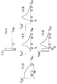
- the second electrical signal S D is processed (encoded) by the coding device 23 in such a way that its energy is concentrated on a sub-range of the second frequency range FB2. This corresponds to a shift in the center of gravity of the spectral function F S, D.
- the coding is preferably carried out in such a way that the center of gravity of the spectral function F S, D is shifted towards higher frequencies, so that only low energy is present at low frequencies compared to the total energy of the second electrical signal S D (FIG. 3c). These low frequencies are then suppressed by the high-pass filter 22, so that in the frequency range from 0 to the cut-off frequency f G1 of the high-pass filter 22, the spectral function F S, D2 is very much smaller (e.g.
- the spectral function F S, D2 can also be almost zero (FIG. 3d). There is therefore a "free space" in the spectral function F S, D2 . Since the energy of the second electrical signal S D was concentrated before the filtering, only a small part of the energy is lost through the filtering, and the second electrical signal S D can be recovered in the optical network termination 6 with sufficient quality.
- the electrical multiplex signal E MUX arises from the received optical signals O TV and O D.
- this multiplex signal E MUX which arises only in the optical network termination 6, the free space present in the spectral function F S, D2 is occupied by the spectral function F S, TV of the first electrical signal S TV .
- the numerical values given in the description are to be understood as examples. Of course, other numerical values and frequency ranges can also be used to apply the principle described. It applies to the first electrical signal S TV that it does not necessarily have to be an analog cable television signal. It can also be another digital signal, for example.
Landscapes
- Engineering & Computer Science (AREA)
- Signal Processing (AREA)
- Computer Networks & Wireless Communication (AREA)
- Multimedia (AREA)
- Optical Communication System (AREA)
- Two-Way Televisions, Distribution Of Moving Picture Or The Like (AREA)
Applications Claiming Priority (2)
| Application Number | Priority Date | Filing Date | Title |
|---|---|---|---|
| DE4438942A DE4438942A1 (de) | 1994-10-31 | 1994-10-31 | Optisches Nachrichtenübertragungssystem für Kabelfernsehsignale und für teilnehmerindividuelle Signale |
| DE4438942 | 1994-10-31 |
Publications (3)
| Publication Number | Publication Date |
|---|---|
| EP0709978A2 true EP0709978A2 (fr) | 1996-05-01 |
| EP0709978A3 EP0709978A3 (fr) | 1998-08-12 |
| EP0709978B1 EP0709978B1 (fr) | 2003-08-27 |
Family
ID=6532181
Family Applications (1)
| Application Number | Title | Priority Date | Filing Date |
|---|---|---|---|
| EP95117135A Expired - Lifetime EP0709978B1 (fr) | 1994-10-31 | 1995-10-31 | Système optique de transmission pour des signaux de télévision par câble et pour des signaux d'abonnés individuels |
Country Status (6)
| Country | Link |
|---|---|
| US (1) | US5748348A (fr) |
| EP (1) | EP0709978B1 (fr) |
| JP (1) | JPH08251578A (fr) |
| AU (1) | AU705175B2 (fr) |
| CA (1) | CA2161732A1 (fr) |
| DE (2) | DE4438942A1 (fr) |
Cited By (1)
| Publication number | Priority date | Publication date | Assignee | Title |
|---|---|---|---|---|
| WO1998018223A1 (fr) * | 1996-10-21 | 1998-04-30 | Siemens Aktiengesellschaft | Procede et dispositif pour la transmission combinee analogique et numerique d'un signal analogique de mesure de c.a. au moyen d'une fibre optique |
Families Citing this family (24)
| Publication number | Priority date | Publication date | Assignee | Title |
|---|---|---|---|---|
| DE19626128A1 (de) * | 1996-06-28 | 1998-01-08 | Sel Alcatel Ag | Sendeeinrichtung, Sendeeinheit und optisches Übertragungssystem zur optischen Übertragung analoger elektrischer Signale |
| DE19635989A1 (de) * | 1996-09-05 | 1998-03-12 | Sel Alcatel Ag | Sendeeinrichtung zur optischen Übertragung von analogen elektrischen Signalen und digitales Übertragungssystem |
| US6115159A (en) * | 1997-03-27 | 2000-09-05 | Telecast Fiber Systems, Inc. | Apparatus for fiber optic triaxial camera interface |
| JP3769109B2 (ja) * | 1997-09-10 | 2006-04-19 | 富士通株式会社 | 光送信装置および光受信装置並びに光通信方法 |
| KR100251692B1 (ko) * | 1997-09-12 | 2000-04-15 | 윤종용 | 광섬유 가입자 망 |
| US6433906B1 (en) * | 1999-09-22 | 2002-08-13 | Scientific-Atlanta, Inc. | Digital optical receiver for cable television systems |
| US6366712B1 (en) * | 2000-03-31 | 2002-04-02 | Marconi Communications, Inc. | Apparatus and method for combining two separate RF signals on a single optical fiber with monitoring and alarm capabilities |
| US6667994B1 (en) * | 2000-06-09 | 2003-12-23 | Scientific-Atlanta, Inc. | Multiplexing digital communication system |
| US8451979B2 (en) * | 2001-06-04 | 2013-05-28 | Calix, Inc. | System for correlating a subscriber unit with a particular subscriber in a passive optical network |
| US7433598B2 (en) * | 2001-06-29 | 2008-10-07 | Broadband Royalty Corp. | Uncooled laser generation of narrowcast CATV signal |
| US7327959B2 (en) | 2001-12-17 | 2008-02-05 | Telecast Fiber Systems, Inc. | Camera-mountable fiber optic transceiver system |
| JP4590948B2 (ja) * | 2004-06-29 | 2010-12-01 | 三菱電機株式会社 | 通信方法および光通信システム |
| JP4804735B2 (ja) * | 2004-09-30 | 2011-11-02 | 富士通株式会社 | 光伝送システム及び光伝送方法 |
| JP2006352288A (ja) * | 2005-06-14 | 2006-12-28 | Net One Systems Co Ltd | 光伝送システム |
| JP4969835B2 (ja) * | 2005-11-14 | 2012-07-04 | 古河電気工業株式会社 | 光波長多重伝送システム |
| JP2009540741A (ja) | 2006-06-16 | 2009-11-19 | トムソン ライセンシング | マルチチャンネルのディジタル・ケーブル・チューナ |
| JP2008113146A (ja) * | 2006-10-30 | 2008-05-15 | Dx Antenna Co Ltd | 光放送システム |
| JP4816787B2 (ja) * | 2009-10-21 | 2011-11-16 | 三菱電機株式会社 | 局側通信装置、加入者側通信装置、通信システムおよび通信方法 |
| SE1200578A1 (sv) | 2012-09-26 | 2014-03-27 | Deltanode Solutions Ab | Distributionsnät för ett distribuerat antennsystem |
| US9401767B2 (en) | 2013-03-12 | 2016-07-26 | CommScope Technology LLC | Optically powered media converter |
| JP5753622B1 (ja) * | 2014-10-20 | 2015-07-22 | 株式会社日本ビデオシステム | 光伝送システム |
| EP3408951B1 (fr) * | 2016-01-25 | 2021-06-30 | Telefonaktiebolaget LM Ericsson (publ) | Procédés et appareil de multiplexage de signaux |
| US10225013B2 (en) * | 2016-12-01 | 2019-03-05 | Arris Enterprises Llc | Channel management to provide narrowcast data services using visible light communication |
| US11973537B2 (en) * | 2022-03-04 | 2024-04-30 | Nokia Solutions And Networks Oy | Flexible rate passive optical network incorporating use of delay modulation |
Citations (3)
| Publication number | Priority date | Publication date | Assignee | Title |
|---|---|---|---|---|
| US4435804A (en) * | 1981-03-13 | 1984-03-06 | Fuji Xerox Co., Ltd. | Sub-signal transmitting system |
| EP0386466A2 (fr) * | 1989-03-08 | 1990-09-12 | Alcatel SEL Aktiengesellschaft | Système optique de transmission d'information dans la zone d'abonné |
| DE4116660A1 (de) * | 1991-05-22 | 1992-11-26 | Standard Elektrik Lorenz Ag | Optisches nachrichtenuebertragungssystem fuer den teilnehmeranschlussbereich mit optischen verstaerkern |
Family Cites Families (19)
| Publication number | Priority date | Publication date | Assignee | Title |
|---|---|---|---|---|
| DE2922418C2 (de) * | 1979-06-01 | 1981-12-03 | Licentia Patent-Verwaltungs-Gmbh, 6000 Frankfurt | Dienstintegriertes Nachrichtenübertragungs- und Vermittlungssystem für Ton, Bild und Daten |
| DE3044657A1 (de) * | 1980-11-27 | 1982-07-08 | Licentia Patent-Verwaltungs-Gmbh, 6000 Frankfurt | "dienstintegriertes digitales uebertragungssystem" |
| DE3044605A1 (de) * | 1980-11-27 | 1982-06-24 | Licentia Patent-Verwaltungs-Gmbh, 6000 Frankfurt | "dienstintegriertes digitales uebertragungssystem" |
| DE3045876A1 (de) * | 1980-12-05 | 1982-07-08 | Licentia Patent-Verwaltungs-Gmbh, 6000 Frankfurt | Dienstintegriertes, digitales uebertragungssystem |
| DE3437772A1 (de) * | 1984-10-16 | 1986-04-24 | Standard Elektrik Lorenz Ag, 7000 Stuttgart | System zum anschluss von teilnehmern an eine zentrale |
| DE3528252A1 (de) * | 1985-08-07 | 1987-02-12 | Standard Elektrik Lorenz Ag | Faseroptische verteileranlage fuer breitbandige signale |
| DE3544393A1 (de) * | 1985-12-16 | 1987-06-19 | Philips Patentverwaltung | Diensteintegrierendes, digitales nachrichtenuebertragungssystem mit einrichtungen zur gemeinsamen uebertragung von schmalband- und breitbandsignalen |
| GB8807050D0 (en) * | 1988-03-24 | 1988-04-27 | British Telecomm | Communication system |
| DE3913300A1 (de) * | 1989-04-22 | 1990-10-25 | Standard Elektrik Lorenz Ag | Optisches nachrichtenuebertragungssystem fuer den teilnehmeranschlussbereich |
| DE3913520A1 (de) * | 1989-04-25 | 1990-10-31 | Standard Elektrik Lorenz Ag | Optisches kabelfernsehuebertragungssystem |
| DE4001039A1 (de) * | 1990-01-16 | 1991-07-18 | Standard Elektrik Lorenz Ag | Optisches kabelfernseh-uebertragungssystem |
| DE4019224A1 (de) * | 1990-06-15 | 1991-12-19 | Standard Elektrik Lorenz Ag | Funk-nachrichtenuebertragungssystem, insbesondere zellulares mobilfunksystem |
| JPH088683B2 (ja) * | 1990-10-09 | 1996-01-29 | 松下電器産業株式会社 | 有料チャネル伝送システム |
| ATE153812T1 (de) * | 1991-02-11 | 1997-06-15 | Sel Alcatel Ag | Optisches nachrichtenübertragungssystem für den teilnehmeranschlussbereich mit optischen verstärkern |
| DE4104084A1 (de) * | 1991-02-11 | 1992-08-13 | Standard Elektrik Lorenz Ag | Optisches nachrichtenuebertragungssystem fuer den teilnehmeranschlussbereich mit optischen verstaerkern |
| US5191456A (en) * | 1991-07-30 | 1993-03-02 | Alcatel Network Systems, Inc. | Efficient feeder fiber loading from distribution fibers |
| US5189673A (en) * | 1991-07-30 | 1993-02-23 | Alcatel Network Systems, Inc. | Method and apparatus for controlling switched video in an optical fiber telecommunications system |
| US5303229A (en) * | 1991-07-31 | 1994-04-12 | Alcatel Network Systems, Inc. | Optical network unit |
| US5181106A (en) * | 1991-07-31 | 1993-01-19 | Alcatel Network Systems, Inc. | Video line shelf arrangement in an optical fiber telecommunications network providing broadband switched video services |
-
1994
- 1994-10-31 DE DE4438942A patent/DE4438942A1/de not_active Withdrawn
-
1995
- 1995-10-26 AU AU34502/95A patent/AU705175B2/en not_active Ceased
- 1995-10-30 CA CA002161732A patent/CA2161732A1/fr not_active Abandoned
- 1995-10-31 DE DE59510776T patent/DE59510776D1/de not_active Expired - Fee Related
- 1995-10-31 EP EP95117135A patent/EP0709978B1/fr not_active Expired - Lifetime
- 1995-10-31 JP JP7283416A patent/JPH08251578A/ja active Pending
- 1995-11-06 US US08/554,272 patent/US5748348A/en not_active Expired - Fee Related
Patent Citations (3)
| Publication number | Priority date | Publication date | Assignee | Title |
|---|---|---|---|---|
| US4435804A (en) * | 1981-03-13 | 1984-03-06 | Fuji Xerox Co., Ltd. | Sub-signal transmitting system |
| EP0386466A2 (fr) * | 1989-03-08 | 1990-09-12 | Alcatel SEL Aktiengesellschaft | Système optique de transmission d'information dans la zone d'abonné |
| DE4116660A1 (de) * | 1991-05-22 | 1992-11-26 | Standard Elektrik Lorenz Ag | Optisches nachrichtenuebertragungssystem fuer den teilnehmeranschlussbereich mit optischen verstaerkern |
Cited By (1)
| Publication number | Priority date | Publication date | Assignee | Title |
|---|---|---|---|---|
| WO1998018223A1 (fr) * | 1996-10-21 | 1998-04-30 | Siemens Aktiengesellschaft | Procede et dispositif pour la transmission combinee analogique et numerique d'un signal analogique de mesure de c.a. au moyen d'une fibre optique |
Also Published As
| Publication number | Publication date |
|---|---|
| JPH08251578A (ja) | 1996-09-27 |
| EP0709978A3 (fr) | 1998-08-12 |
| EP0709978B1 (fr) | 2003-08-27 |
| US5748348A (en) | 1998-05-05 |
| DE4438942A1 (de) | 1996-05-02 |
| DE59510776D1 (de) | 2003-10-02 |
| AU3450295A (en) | 1996-05-09 |
| CA2161732A1 (fr) | 1996-05-01 |
| AU705175B2 (en) | 1999-05-20 |
Similar Documents
| Publication | Publication Date | Title |
|---|---|---|
| EP0709978B1 (fr) | Système optique de transmission pour des signaux de télévision par câble et pour des signaux d'abonnés individuels | |
| EP0727889B1 (fr) | Système de transmission optique pour signaux de télévision par câble et pour signaux de vidéo et télécommunication | |
| EP0499065B1 (fr) | Système de transmission optique pour zone d'abonnés utilisant des amplificateurs optiques | |
| EP0053236B1 (fr) | Système de transmission numérique à service intégré | |
| DE19654173A1 (de) | Vorrichtung und Verfahren zur schnellen Datenübertragung über eine Abzweigleitung eines Nachrichtenübertragungssystems auf Hochspannungsleitungen | |
| EP0227164A2 (fr) | Système de transmission à intégration de services d'informations numériques avec des dispositifs pour la transmission simultanée de signaux à large bande et à bande étroite | |
| EP0386482B1 (fr) | Système de transmission optique pour connexion d'abonné | |
| EP1342303A1 (fr) | Dispositif et procede permettant de transmettre des donnees de transmission numeriques | |
| EP0386466B1 (fr) | Système optique de transmission d'information dans la zone d'abonné | |
| DE3632047C2 (de) | Optisches Nachrichtenübertragungssystem für Schmalband- und Breitband-Nachrichtensignale | |
| DE19643872A1 (de) | Optische Netzabschlußeinheit eines hybriden Glasfaser-Koaxialkabel-Zugangsnetzes | |
| EP0031014B1 (fr) | Système de télécommunications | |
| EP0084371A2 (fr) | Système à fréquences porteuses pour fonctionnement à quatre fils | |
| EP0854597A2 (fr) | Système de transmission d'informations optiques via plusieurs lignes de transmission optique | |
| EP0881791A2 (fr) | Système de transmission optique d'informations | |
| DE4226838B4 (de) | Optisches, breitbandiges Nachrichtenübertragungssystem für Kommunikations- und Verteildienste | |
| EP0162994A1 (fr) | Réseau de communication et son utilisation | |
| DE3208308A1 (de) | Verfahren zum uebertragen von frequenzmodulierten hoerrundfunksignalen ueber ein digitales breitbandverteilnetz | |
| EP0031458A2 (fr) | Système de transmission à guides d'ondes de lumière et à multiplex à fréquence | |
| EP0645908B1 (fr) | Procédé de multiplexage par partage du temps | |
| DE3935183C2 (de) | Kabelfernseh-Übertragungssystem | |
| EP0545030B1 (fr) | Méthode de préparation de signaux de sources d'image avec ou sans signaux de son et utilisation correspondante | |
| EP0668707A2 (fr) | Réseau de raccordement | |
| DE19939540A1 (de) | Verfahren zum Übertragen eines Informationssignals | |
| EP0781030A2 (fr) | Méthode pour l'opération d'un réseau téléphonique et téléphone numérique |
Legal Events
| Date | Code | Title | Description |
|---|---|---|---|
| PUAI | Public reference made under article 153(3) epc to a published international application that has entered the european phase |
Free format text: ORIGINAL CODE: 0009012 |
|
| AK | Designated contracting states |
Kind code of ref document: A2 Designated state(s): CH DE ES FR GB IT LI SE |
|
| PUAL | Search report despatched |
Free format text: ORIGINAL CODE: 0009013 |
|
| AK | Designated contracting states |
Kind code of ref document: A3 Designated state(s): CH DE ES FR GB IT LI SE |
|
| 17P | Request for examination filed |
Effective date: 19980724 |
|
| 17Q | First examination report despatched |
Effective date: 19990820 |
|
| GRAH | Despatch of communication of intention to grant a patent |
Free format text: ORIGINAL CODE: EPIDOS IGRA |
|
| GRAH | Despatch of communication of intention to grant a patent |
Free format text: ORIGINAL CODE: EPIDOS IGRA |
|
| GRAA | (expected) grant |
Free format text: ORIGINAL CODE: 0009210 |
|
| RAP1 | Party data changed (applicant data changed or rights of an application transferred) |
Owner name: ALCATEL |
|
| AK | Designated contracting states |
Designated state(s): CH DE ES FR GB IT LI SE |
|
| PG25 | Lapsed in a contracting state [announced via postgrant information from national office to epo] |
Ref country code: IT Free format text: LAPSE BECAUSE OF FAILURE TO SUBMIT A TRANSLATION OF THE DESCRIPTION OR TO PAY THE FEE WITHIN THE PRE;WARNING: LAPSES OF ITALIAN PATENTS WITH EFFECTIVE DATE BEFORE 2007 MAY HAVE OCCURRED AT ANY TIME BEFORE 2007. THE CORRECT EFFECTIVE DATE MAY BE DIFFERENT FROM THE ONE RECORDED.SCRIBED TIME-LIMIT Effective date: 20030827 Ref country code: GB Free format text: LAPSE BECAUSE OF FAILURE TO SUBMIT A TRANSLATION OF THE DESCRIPTION OR TO PAY THE FEE WITHIN THE PRESCRIBED TIME-LIMIT Effective date: 20030827 Ref country code: FR Free format text: LAPSE BECAUSE OF FAILURE TO SUBMIT A TRANSLATION OF THE DESCRIPTION OR TO PAY THE FEE WITHIN THE PRESCRIBED TIME-LIMIT Effective date: 20030827 |
|
| REG | Reference to a national code |
Ref country code: GB Ref legal event code: FG4D Free format text: NOT ENGLISH |
|
| REG | Reference to a national code |
Ref country code: CH Ref legal event code: EP |
|
| REF | Corresponds to: |
Ref document number: 59510776 Country of ref document: DE Date of ref document: 20031002 Kind code of ref document: P |
|
| PG25 | Lapsed in a contracting state [announced via postgrant information from national office to epo] |
Ref country code: LI Free format text: LAPSE BECAUSE OF NON-PAYMENT OF DUE FEES Effective date: 20031031 Ref country code: CH Free format text: LAPSE BECAUSE OF NON-PAYMENT OF DUE FEES Effective date: 20031031 |
|
| PG25 | Lapsed in a contracting state [announced via postgrant information from national office to epo] |
Ref country code: SE Free format text: LAPSE BECAUSE OF FAILURE TO SUBMIT A TRANSLATION OF THE DESCRIPTION OR TO PAY THE FEE WITHIN THE PRESCRIBED TIME-LIMIT Effective date: 20031127 |
|
| PG25 | Lapsed in a contracting state [announced via postgrant information from national office to epo] |
Ref country code: ES Free format text: LAPSE BECAUSE OF FAILURE TO SUBMIT A TRANSLATION OF THE DESCRIPTION OR TO PAY THE FEE WITHIN THE PRESCRIBED TIME-LIMIT Effective date: 20031208 |
|
| GBV | Gb: ep patent (uk) treated as always having been void in accordance with gb section 77(7)/1977 [no translation filed] |
Effective date: 20030827 |
|
| REG | Reference to a national code |
Ref country code: CH Ref legal event code: PL |
|
| PLBE | No opposition filed within time limit |
Free format text: ORIGINAL CODE: 0009261 |
|
| STAA | Information on the status of an ep patent application or granted ep patent |
Free format text: STATUS: NO OPPOSITION FILED WITHIN TIME LIMIT |
|
| 26N | No opposition filed |
Effective date: 20040528 |
|
| EN | Fr: translation not filed | ||
| PGFP | Annual fee paid to national office [announced via postgrant information from national office to epo] |
Ref country code: DE Payment date: 20061023 Year of fee payment: 12 |
|
| PG25 | Lapsed in a contracting state [announced via postgrant information from national office to epo] |
Ref country code: DE Free format text: LAPSE BECAUSE OF NON-PAYMENT OF DUE FEES Effective date: 20080501 |