EP0708882B1 - Auspufftopf für verbrennungsmotor, insbesondere einzylinder-dieselmotor - Google Patents
Auspufftopf für verbrennungsmotor, insbesondere einzylinder-dieselmotor Download PDFInfo
- Publication number
- EP0708882B1 EP0708882B1 EP94918500A EP94918500A EP0708882B1 EP 0708882 B1 EP0708882 B1 EP 0708882B1 EP 94918500 A EP94918500 A EP 94918500A EP 94918500 A EP94918500 A EP 94918500A EP 0708882 B1 EP0708882 B1 EP 0708882B1
- Authority
- EP
- European Patent Office
- Prior art keywords
- exhaust silencer
- cylinder head
- screws
- wall section
- silencer according
- Prior art date
- Legal status (The legal status is an assumption and is not a legal conclusion. Google has not performed a legal analysis and makes no representation as to the accuracy of the status listed.)
- Expired - Lifetime
Links
Images


Classifications
-
- F—MECHANICAL ENGINEERING; LIGHTING; HEATING; WEAPONS; BLASTING
- F01—MACHINES OR ENGINES IN GENERAL; ENGINE PLANTS IN GENERAL; STEAM ENGINES
- F01N—GAS-FLOW SILENCERS OR EXHAUST APPARATUS FOR MACHINES OR ENGINES IN GENERAL; GAS-FLOW SILENCERS OR EXHAUST APPARATUS FOR INTERNAL-COMBUSTION ENGINES
- F01N13/00—Exhaust or silencing apparatus characterised by constructional features
- F01N13/18—Construction facilitating manufacture, assembly, or disassembly
- F01N13/1861—Construction facilitating manufacture, assembly, or disassembly the assembly using parts formed by casting or moulding
-
- F—MECHANICAL ENGINEERING; LIGHTING; HEATING; WEAPONS; BLASTING
- F01—MACHINES OR ENGINES IN GENERAL; ENGINE PLANTS IN GENERAL; STEAM ENGINES
- F01N—GAS-FLOW SILENCERS OR EXHAUST APPARATUS FOR MACHINES OR ENGINES IN GENERAL; GAS-FLOW SILENCERS OR EXHAUST APPARATUS FOR INTERNAL-COMBUSTION ENGINES
- F01N1/00—Silencing apparatus characterised by method of silencing
- F01N1/16—Silencing apparatus characterised by method of silencing by using movable parts
- F01N1/165—Silencing apparatus characterised by method of silencing by using movable parts for adjusting flow area
-
- F—MECHANICAL ENGINEERING; LIGHTING; HEATING; WEAPONS; BLASTING
- F01—MACHINES OR ENGINES IN GENERAL; ENGINE PLANTS IN GENERAL; STEAM ENGINES
- F01N—GAS-FLOW SILENCERS OR EXHAUST APPARATUS FOR MACHINES OR ENGINES IN GENERAL; GAS-FLOW SILENCERS OR EXHAUST APPARATUS FOR INTERNAL-COMBUSTION ENGINES
- F01N13/00—Exhaust or silencing apparatus characterised by constructional features
- F01N13/18—Construction facilitating manufacture, assembly, or disassembly
- F01N13/1805—Fixing exhaust manifolds, exhaust pipes or pipe sections to each other, to engine or to vehicle body
-
- F—MECHANICAL ENGINEERING; LIGHTING; HEATING; WEAPONS; BLASTING
- F01—MACHINES OR ENGINES IN GENERAL; ENGINE PLANTS IN GENERAL; STEAM ENGINES
- F01N—GAS-FLOW SILENCERS OR EXHAUST APPARATUS FOR MACHINES OR ENGINES IN GENERAL; GAS-FLOW SILENCERS OR EXHAUST APPARATUS FOR INTERNAL-COMBUSTION ENGINES
- F01N13/00—Exhaust or silencing apparatus characterised by constructional features
- F01N13/18—Construction facilitating manufacture, assembly, or disassembly
- F01N13/1805—Fixing exhaust manifolds, exhaust pipes or pipe sections to each other, to engine or to vehicle body
- F01N13/1827—Sealings specially adapted for exhaust systems
-
- F—MECHANICAL ENGINEERING; LIGHTING; HEATING; WEAPONS; BLASTING
- F01—MACHINES OR ENGINES IN GENERAL; ENGINE PLANTS IN GENERAL; STEAM ENGINES
- F01N—GAS-FLOW SILENCERS OR EXHAUST APPARATUS FOR MACHINES OR ENGINES IN GENERAL; GAS-FLOW SILENCERS OR EXHAUST APPARATUS FOR INTERNAL-COMBUSTION ENGINES
- F01N13/00—Exhaust or silencing apparatus characterised by constructional features
- F01N13/18—Construction facilitating manufacture, assembly, or disassembly
- F01N13/1833—Construction facilitating manufacture, assembly, or disassembly specially adapted for small internal combustion engines, e.g. used in model applications
-
- F—MECHANICAL ENGINEERING; LIGHTING; HEATING; WEAPONS; BLASTING
- F02—COMBUSTION ENGINES; HOT-GAS OR COMBUSTION-PRODUCT ENGINE PLANTS
- F02B—INTERNAL-COMBUSTION PISTON ENGINES; COMBUSTION ENGINES IN GENERAL
- F02B75/00—Other engines
- F02B75/16—Engines characterised by number of cylinders, e.g. single-cylinder engines
-
- F—MECHANICAL ENGINEERING; LIGHTING; HEATING; WEAPONS; BLASTING
- F01—MACHINES OR ENGINES IN GENERAL; ENGINE PLANTS IN GENERAL; STEAM ENGINES
- F01N—GAS-FLOW SILENCERS OR EXHAUST APPARATUS FOR MACHINES OR ENGINES IN GENERAL; GAS-FLOW SILENCERS OR EXHAUST APPARATUS FOR INTERNAL-COMBUSTION ENGINES
- F01N2450/00—Methods or apparatus for fitting, inserting or repairing different elements
- F01N2450/24—Methods or apparatus for fitting, inserting or repairing different elements by bolts, screws, rivets or the like
-
- F—MECHANICAL ENGINEERING; LIGHTING; HEATING; WEAPONS; BLASTING
- F02—COMBUSTION ENGINES; HOT-GAS OR COMBUSTION-PRODUCT ENGINE PLANTS
- F02B—INTERNAL-COMBUSTION PISTON ENGINES; COMBUSTION ENGINES IN GENERAL
- F02B3/00—Engines characterised by air compression and subsequent fuel addition
- F02B3/06—Engines characterised by air compression and subsequent fuel addition with compression ignition
-
- F—MECHANICAL ENGINEERING; LIGHTING; HEATING; WEAPONS; BLASTING
- F05—INDEXING SCHEMES RELATING TO ENGINES OR PUMPS IN VARIOUS SUBCLASSES OF CLASSES F01-F04
- F05C—INDEXING SCHEME RELATING TO MATERIALS, MATERIAL PROPERTIES OR MATERIAL CHARACTERISTICS FOR MACHINES, ENGINES OR PUMPS OTHER THAN NON-POSITIVE-DISPLACEMENT MACHINES OR ENGINES
- F05C2201/00—Metals
- F05C2201/02—Light metals
- F05C2201/021—Aluminium
Definitions
- the invention relates to a muffler on an internal combustion engine, in particular a single-cylinder diesel engine, with an inlet opening and an outlet opening for the exhaust gas, according to the preamble of claim 1.
- Such a muffler described in British Patent 1,447,877 is braced against the cylinder head by means of through bolts, the hollow shape of the muffler being stiffened by means of the tubular sleeves against deformation under the action of the tensile forces of the through bolts.
- the aim of the present invention is to make the muffler simple and lightweight and to enable it to be stiffened and fastened without great effort.
- the particular simplification is that the through screws used to fasten the muffler to the cylinder head also serve to stiffen the muffler from the side without stressing it in the pulling direction of the through screws. Because the outer wall section is fixed on the ends of the sleeves that are distant from the cylinder head, tension on the one hand and unwanted vibrations of the muffler on the other hand can be practically avoided. As a result, it can be produced with a relatively thin wall thickness.
- a muffler made of a one-piece, cast metal housing is preferred. The preferred casting method is casting from aluminum with a sand core, which is crushed and removed after casting.
- the muffler also acts as a resonator, ie it takes over the sound damping of the exhaust gas if its volume is matched accordingly.
- special muffler devices can be connected to the muffler, namely in the event that soundproofing cannot otherwise be achieved within the prescribed limits.
- Particularly simple solutions are, for example Sieve insert in the area of the outlet opening or a spring-loaded closure flap.
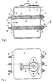
- the muffler 1 shown in FIGS. 1 and 2 is a one-piece casting, preferably made of aluminum.
- a flange 3 is cast on, which is provided for direct connection to the cylinder head.
- the flange 3 has three bores 23 for through screws 4, the ends 5 of which face the cylinder head are provided with a thread with which they can be screwed into corresponding threaded bores of the cylinder head.
- the through screws 4 pass through the entire interior of the muffler 1 and their outer ends 6 protrude through bores 21 of an outer wall section 7 of the muffler 1.
- the through screws 4 are clamped by means of nuts 8 against sleeves 9, through which they are inserted.
- the sleeves 9 are supported on the one hand against the inner wall 10 of the inner wall section 2; on the other hand, they end within the bores 21 in the outer wall section 7. There, a seal 11 is deformed between the associated end of a sleeve 9 and a bushing 12 clamped between nut 8 and sleeve 9, so that the seal 11 is effective on the inside of the bore 21 is present. 3 and 4, this seal connection is shown enlarged.
- the flange 3 surrounds the inlet opening 13 of the exhaust gas, which in turn exits the muffler 1 through the outlet opening 14.
- the outlet opening is closed by a spring-loaded flap 15; under the action of the exhaust gas pulsations, the flap 15 lifts slightly from its seat 16 against the pressure of the spring 17, the exhaust gas pulsations being smoothed out while reducing the noise.
- the through screws 4 each have at their two ends 5, 6 external threads, and in addition to these threads each have a typical turn 18 for lag screws.
- the wall of the muffler 1 has thickenings 19 in the region of the bores 21 of the outer wall section 7, so that better guidance for the sleeves 9 and the bushes 12 is achieved thanks to correspondingly lengthened bores 21.
- Fig. 3 shows an enlarged section according to III of Fig. 1, in the position of the sleeve 9 and the socket 12 after tightening the nut 8.
- the seal 11 is already squeezed accordingly, i. H. it completely fills the remaining cavity between the bushing 12 and the sleeve 9 and lies firmly and sealingly against the inner wall of the bore 21 in the outer wall part 7.
- the seal 11 is shown here as a ring with an approximately square cross section; the bushing 12 has a conical end face 20 which facilitates the deformation of the seal 11 made of soft metal such as copper, while the nut 8 is increasingly screwed onto the externally threaded end 6 of the through screw 4. 4, the bore 21 of the outer wall section 7 is partially exposed.
- the existing cavity is completely filled, the volume of the seal being dimensioned approximately such that, in the end position of the bushing 12, its inner end face 22, as shown in FIG. 3, on the opposite end face of the sleeve 9 is present. 3 there is a firm compression of the seal 11 within the bore 21, so that a full and permanent seal is achieved.
- This tight seal also serves to stiffen the muffler in its entirety, the three through screws 4 together with the sleeves 9 and bushings 12 located thereon forming a stable, largely structure-borne sound-free unit.
Landscapes
- Engineering & Computer Science (AREA)
- Chemical & Material Sciences (AREA)
- Combustion & Propulsion (AREA)
- Mechanical Engineering (AREA)
- General Engineering & Computer Science (AREA)
- Exhaust Silencers (AREA)
Abstract
Description
- Die Erfindung betrifft einen Auspufftopf an einem Verbrennungsmotor, insbesondere Einzylinder-Dieselmotor, mit einer Eintrittsöffnung und einer Austrittsöffnung für das Abgas, gemäß dem Oberbegriff von Anspruch 1.
- Ein derartiger in der britischen Patentschrift 1 447 877 beschriebener Auspufftopf ist mittels Durchgangsschrauben gegen den Zylinderkopf verspannt, wobei die Hohlform des Auspufftopfs mittels der rohrförmigen Hülsen gegen Verformen unter der Wirkung der Zugkräfte der Durchgangsschrauben ausgesteift ist.
- Demgegenüber besteht das Ziel der vorliegenden Erfindung darin, den Auspufftopf einfach und leichtgewichtig auszubilden und dessen Aussteifung und Befestigung ohne großen Aufwand zu ermöglichen.
- Diese Aufgabe wird erfindungsgemäß gemäß dem Kennzeichen von Anspruch 1 gelöst.
- Die besondere Vereinfachung besteht darin, daß die der Befestigung des Auspufftopfs am Zylinderkopf dienenden Durchgangsschrauben gleichzeitig der seitlichen Aussteifung des Auspufftopfs dienen, ohne diesen in Zugrichtung der Durchgangsschrauben zu belasten. Dadurch, daß der äußere Wandabschnitt auf den vom Zylinderkopf entfernten Enden der Hülsen zwängungsfrei festgelegt ist, können einerseits Verspannungen, andererseits unerwünschte Schwingungen des Auspufftopfs praktisch vermieden werden. Er kann dadurch mit verhältnismäßig dünner Wandstärke hergestellt werden. Bevorzugt kommt ein Auspufftopf aus einem einteiligen, durch Gießen hergestellten Metallgehäuse in Frage. Als Gießverfahren eignet sich bevorzugt das Gießen aus Aluminium mit einem Sandkern, welcher nach dem Gießen zerkleinert und entfernt wird.
- Der Auspufftopf wirkt gleichzeitig als Resonator, d.h. er übernimmt bei entsprechender Abstimmung seines Volumens die Schalldämpfung des Abgases. Zusätzlich können besondere Schalldämpfereinrichtungen mit dem Auspufftopf verbunden sein, nämlich für den Fall, daß sich sonst eine Schalldämpfung innerhalb vorgeschriebener Grenzen nicht erzielen läßt. Besonders einfache Lösungen sind z.B. ein Siebeinsatz im Bereich der Austrittsöffnung oder eine federbelastete Verschlußklappe.
- Im folgenden wird ein Ausführungsbeispiel der Erfindung anhand der Zeichnung erläutert. Es zeigt
- Fig. 1
- einen Querschnitt durch den Auspufftopf,
- Fig. 2
- eine Draufsicht zu Fig. 1,
- Fig. 3
- einen vergrößerten Ausschnitt III gemäß Fig. 1 und
- Fig. 4
- den Ausschnitt gemäß Fig. 3 vor der Verformung der Dichtung.
- Der in den Fig. 1 und 2 dargestellte Auspufftopf 1 ist ein einteiliges Gußteil, bevorzugt aus Aluminium. An der Außenseite seines Wandabschnitts 2, welche dem (nicht dargestellten) Zylinderkopf zugewandt ist, ist ein Flansch 3 angegossen, welcher für den direkten Anschluß am Zylinderkopf vorgesehen ist. Der Flansch 3 besitzt drei Bohrungen 23 für Durchgangsschrauben 4, deren dem Zylinderkopf zugewandte Enden 5 mit einem Gewinde versehen sind, mit welchem Sie in entsprechende Gewindebohrungen des Zylinderkopfs einschraubbar sind. Die Durchgangsschrauben 4 durchqueren den gesamten Innenraum des Auspufftopfs 1 und ihre äußeren Enden 6 ragen durch Bohrungen 21 eines äußeren Wandabschnitts 7 des Auspufftopfs 1 hindurch. Die Durchgangsschrauben 4 sind mittels Muttern 8 gegen Hülsen 9 verspannt, durch die sie hindurchgesteckt sind. Die Hülsen 9 stützen sich einerseits gegen die Innenwand 10 des inneren Wandabschnitts 2 ab; andererseits enden sie innerhalb der Bohrungen 21 im äußeren Wandabschnitt 7. Dort wird jeweils eine Dichtung 11 zwischen dem zugeordneten Ende einer Hülse 9 und einer zwischen Mutter 8 und Hülse 9 eingespannten Buchse 12 verformt, so daß die Dichtung 11 wirksam an der Innenseite der Bohrung 21 anliegt. In den Fig. 3 und 4 ist dieser Dichtungsanschluß vergrößert dargestellt.
- Der Flansch 3 umschließt die Eintrittsöffnung 13 des Abgases, welches aus dem Auspufftopf 1 wiederum durch die Austrittsöffnung 14 austritt. Aus Gründen der Geräuschdämpfung ist die Austrittsöffnung durch eine federbelastete Klappe 15 verschlossen; unter der Wirkung der Abgaspulsationen hebt die Klappe 15 von deren Sitz 16 gegen den Druck der Feder 17 geringfügig ab, wobei die Abgaspulsationen unter gleichzeitiger Reduzierung der Geräuschbildung geglättet werden.
- Die Durchgangsschrauben 4 besitzen jeweils an ihren beiden Enden 5, 6 Außengewinde, und außerdem im Anschluß an diese Gewinde jeweils eine für Zugschrauben typische Eindrehung 18.
- Gemäß Fig. 2 wird deutlich, daß die Wand des Auspufftopfs 1 im Bereich der Bohrungen 21 des äußeren Wandabschnitts 7 Verdickungen 19 besitzt, so daß dank entsprechend verlängerter Bohrungen 21 eine bessere Führung für die Hülsen 9 und die Buchsen 12 erzielt wird.
- Fig. 3 zeigt einen vergrößterten Ausschnitt gemäß III der Fig. 1, und zwar in der Position der Hülse 9 und der Buchse 12 nach dem Festspannen der Mutter 8. Die Dichtung 11 ist hier bereits entsprechend verquetscht, d. h. sie füllt den verbleibenden Hohlraum zwischen Buchse 12 und Hülse 9 voll aus und legt sich fest und dichtend an die Innenwand der Bohrung 21 im äußeren Wandteil 7 an.
- Zur Verdeutlichung ist in Fig. 4 der Zustand vor dem Verformen der Dichtung 11 dargestellt. Die Dichtung 11 ist hier als Ring mit etwa quadratischem Querschnitt dargestellt; die Buchse 12 besitzt eine konische Endfläche 20, welche die Verformung der aus weichem Metall wie Kupfer bestehenden Dichtung 11 erleichtert, während die Mutter 8 zunehmend auf das mit Außengewinde versehene Ende 6 der Durchgangsschraube 4 aufgeschraubt wird. Gemäß Fig. 4 liegt die Bohrung 21 des äußeren Wandabschnitts 7 teilweise frei. Im Zuge der Verformung der Dichtung 11 wird der vorhandene Hohlraum vollständig ausgefüllt, wobei das Volumen der Dichtung etwa so bemessen ist, daß in der Endstellung der Buchse 12 deren innere Stirnseite 22, wie in Fig. 3 dargestellt, an der gegenüberliegenden Stirnseite der Hülse 9 anliegt. In der Endstellung gemäß Fig. 3 kommt es zu einer festen Verpressung der Dichtung 11 innerhalb der Bohrung 21, so daß eine vollwertige und dauerhafte Abdichtung erzielt wird. Dieser feste Dichtungsschluß dient gleichzeitig der Aussteifung des Auspufftopfs in seiner Gesamtheit, wobei die drei Durchgangsschrauben 4 zusammen mit den darauf befindlichen Hülsen 9 und Buchsen 12 eine in sich stabile, weitgehend körperschallfreie Baueinheit bilden.
Claims (10)
- Auspufftopf an einem Verbrennungsmotor, insbesondere Einzylinder-Dieselmotor, mit einer Eintrittsöffnung (13) und einer Austrittsöffnung (14) für das Abgas und mit den folgenden Merkmalen:1.1 er besitzt für den direkten Anschluß am Zylinderkopf einen die Eintrittsöffnung (13) enthaltenden Flansch (3) an der Außenseite seines dem Zylinderkopf benachbarten inneren Wandabschnitts (2);1.2 er ist am Zylinderkopf mittels Durchgangsschrauben (4) befestigt, deren dem Flansch abgewandte Enden durch Bohrungen (21) in dem dem Flansch (3) gegenüberliegenden äußeren Wandabschnitt (7) des Auspufftopfs (1) hindurch ragen;1.3 über die Durchgangsschrauben (4) sind rohrförmige Hülsen (9) gesteckt, die an der Innenseite des dem Zylinderkopf benachbarten inneren Wandabschnitts (2) des Auspufftopfs (1) abgestützt sind;1.4 die Durchgangsschrauben (4) sind an ihren vom Zylinderkopf entfernten Enden (6) mittels Muttern (8) auf Zug festgespannt;gekennzeichnet durch die folgenden Merkmale:1.5 die vom Zylinderkopf entfernten Enden der Hülsen (9) enden jeweils innerhalb einer Bohrung (21) des äußeren Wandabschnitts (7) des Auspufftopfs;1.6 die Bohrungen (21) sind gegenüber den Durchgangsschrauben (4) abgedichtet, indem die in den Bohrungen (21) angeordneten Enden der Hülsen (9) mittels eines durch die Zugspannung der Durchgangsschrauben (4) verformbaren Dichtungselements (11) gegenüber der Innenwand der Bohrung (21) festgelegt und abgedichtet sind.
- Auspufftopf nach Anspruch 1,
dadurch gekennzeichnet,
daß der Auspufftopf aus einem einteiligen, durch Gießen hergestellten Metallgehäuse besteht. - Auspufftopf nach Anspruch 1,
dadurch gekennzeichnet,
daß die Muttern (8) gegen die rohrförmigen Hülsen (9) verspannt sind. - Auspufftopf nach Anspruch 1,
dadurch gekennzeichnet,
daß an der Außenseite des Dichtungselements (11), zwischen diesem und den Muttern (8) der Durchgangsschrauben (4) eine Buchse (12) aufgesteckt ist, wobei das Dichtungselement (11) zwischen Buchse (12) und dem benachbarten Ende der zugeordneten Hülse (9) verformt wird. - Auspufftopf nach Anspruch 1,
dadurch gekennzeichnet,
daß das Dichtungselement (11) aus einem leicht verformbaren metallenen Werkstoff, vorzugsweise Kupfer, besteht. - Auspufftopf nach Anspruch 4,
dadurch gekennzeichnet,
daß der Außendurchmesser der Buchse (12) genau jenem der Hülse (9) entspricht. - Auspufftopf nach Anspruch 1,
dadurch gekennzeichnet,
daß er aus Aluminiumguß besteht. - Auspufftopf nach Anspruch 7,
dadurch gekennzeichnet,
daß er mit Ausnahme des Flansches (3) mit etwa gleicher Wandstärke gegossen ist. - Auspufftopf nach Anspruch 1,
dadurch gekennzeichnet,
daß sein äußerer Wandabschnitt (7) parallel zu seinem dem Zylinderkopf zugeordneten inneren Wandabschnitt (2) verläuft. - Auspufftopf nach Anspruch 9,
dadurch gekennzeichnet,
daß die Austrittsöffnung (14) in einem zu den parallelen Wandabschnitten (2, 7) quer verlaufenden Wandteil vorgesehen ist.
Applications Claiming Priority (3)
| Application Number | Priority Date | Filing Date | Title |
|---|---|---|---|
| DE4323644 | 1993-07-15 | ||
| DE4323644A DE4323644A1 (de) | 1993-07-15 | 1993-07-15 | Auspufftopf für Verbrennungsmotor, insbesondere Einzylinder-Dieselmotor |
| PCT/IB1994/000201 WO1995002755A1 (de) | 1993-07-15 | 1994-07-05 | Auspufftopf für verbrennungsmotor, insbesondere einzylinder-dieselmotor |
Publications (2)
| Publication Number | Publication Date |
|---|---|
| EP0708882A1 EP0708882A1 (de) | 1996-05-01 |
| EP0708882B1 true EP0708882B1 (de) | 1997-01-22 |
Family
ID=6492830
Family Applications (1)
| Application Number | Title | Priority Date | Filing Date |
|---|---|---|---|
| EP94918500A Expired - Lifetime EP0708882B1 (de) | 1993-07-15 | 1994-07-05 | Auspufftopf für verbrennungsmotor, insbesondere einzylinder-dieselmotor |
Country Status (4)
| Country | Link |
|---|---|
| EP (1) | EP0708882B1 (de) |
| AU (1) | AU6980294A (de) |
| DE (2) | DE4323644A1 (de) |
| WO (1) | WO1995002755A1 (de) |
Families Citing this family (3)
| Publication number | Priority date | Publication date | Assignee | Title |
|---|---|---|---|---|
| EP0758175B1 (de) * | 1995-01-05 | 2005-06-08 | Ntt Mobile Communications Network Inc. | Kommunikationsvermittungssystem und -verfahren |
| GB0327401D0 (en) * | 2003-11-25 | 2003-12-31 | Emmett Malcolm D | Silencer for exhaust systems |
| DE102011005155A1 (de) | 2011-03-04 | 2012-09-06 | J. Eberspächer GmbH & Co. KG | Abgasanlagenkomponente |
Family Cites Families (3)
| Publication number | Priority date | Publication date | Assignee | Title |
|---|---|---|---|---|
| AU464733B2 (en) * | 1972-10-25 | 1975-09-04 | Tecumseh Products Company | Muffler |
| JPH06575Y2 (ja) * | 1988-06-16 | 1994-01-05 | 川崎重工業株式会社 | 内燃機関用マフラー |
| US4866934A (en) * | 1989-01-11 | 1989-09-19 | Brunswick Corporation | Marine drive exhaust system with shaped O-ring seals |
-
1993
- 1993-07-15 DE DE4323644A patent/DE4323644A1/de not_active Withdrawn
-
1994
- 1994-07-05 AU AU69802/94A patent/AU6980294A/en not_active Abandoned
- 1994-07-05 DE DE59401668T patent/DE59401668D1/de not_active Expired - Fee Related
- 1994-07-05 EP EP94918500A patent/EP0708882B1/de not_active Expired - Lifetime
- 1994-07-05 WO PCT/IB1994/000201 patent/WO1995002755A1/de not_active Ceased
Also Published As
| Publication number | Publication date |
|---|---|
| AU6980294A (en) | 1995-02-13 |
| WO1995002755A1 (de) | 1995-01-26 |
| DE59401668D1 (de) | 1997-03-06 |
| EP0708882A1 (de) | 1996-05-01 |
| DE4323644A1 (de) | 1995-01-26 |
Similar Documents
| Publication | Publication Date | Title |
|---|---|---|
| EP1270891B1 (de) | Vorrichtung zur Befestigung eines Abgasturboladers an einem Abgaskrümmer einer Brennkraftmaschine | |
| DE19606698B4 (de) | Geräuschunterdrücker für Verdrängungskompressoren | |
| DE3050893C2 (de) | ||
| EP0632195B1 (de) | Abdichtung zweier Gehäuseteile | |
| DE10232528B4 (de) | Magnetventil mit Ölfilter für variable Nockenwellensteuerung | |
| DE60217064T2 (de) | Kraftstoff-einspritzdüse | |
| WO1995002755A1 (de) | Auspufftopf für verbrennungsmotor, insbesondere einzylinder-dieselmotor | |
| EP0832352B1 (de) | Rohrmodul | |
| DE102007037461A1 (de) | Brennkraftmaschine mit einem Zylinderkurbelgehäuse und einem Zylindergehäuseunterteil | |
| DE2726089A1 (de) | Ventilplatte | |
| DE2618241A1 (de) | Brennkraftmaschine | |
| DE4313091A1 (de) | Flansch zur Befestigung von Rohren | |
| DE4230710C2 (de) | Vorrichtung zur Abdichtung zwischen Ölwanne und Kurbelwellengehäuse einer Brennkraftmaschine | |
| DE4323642A1 (de) | Schalldämpfer für Verbrennungsmotor, insbesondere Einzylinder-Dieselmotor | |
| DE10225573B4 (de) | Zweitaktmotor und Verfahren zu dessen Herstellung | |
| DE69108706T2 (de) | Gasverdichter. | |
| AT381143B (de) | Hubkolben-brennkraftmaschine | |
| EP0141992B1 (de) | Mehrteiliger Kolben für Verbrennungsmotoren mit teilisoliertem Kühlölkanal | |
| AT413299B (de) | Pleuelstange | |
| DE19756390A1 (de) | Kurbelgehäuse aus insbesondere Leichtmetall | |
| WO2000003138A1 (de) | Verbrennungsmotor | |
| DE963606C (de) | Tauchkolbenkompressor fuer Haushaltkuehlschraenke | |
| DE19608018B4 (de) | Gehäuse für eine Hubkolben-Brennkraftmaschine | |
| DE960594C (de) | Brennkraftmaschine mit V-foermig angeordneten Zylindern | |
| EP0952328A2 (de) | Kurbelgehäuse einer Brennkraftmaschine |
Legal Events
| Date | Code | Title | Description |
|---|---|---|---|
| PUAI | Public reference made under article 153(3) epc to a published international application that has entered the european phase |
Free format text: ORIGINAL CODE: 0009012 |
|
| 17P | Request for examination filed |
Effective date: 19950817 |
|
| AK | Designated contracting states |
Kind code of ref document: A1 Designated state(s): DE GB IT |
|
| GRAG | Despatch of communication of intention to grant |
Free format text: ORIGINAL CODE: EPIDOS AGRA |
|
| 17Q | First examination report despatched |
Effective date: 19960513 |
|
| GRAH | Despatch of communication of intention to grant a patent |
Free format text: ORIGINAL CODE: EPIDOS IGRA |
|
| GRAH | Despatch of communication of intention to grant a patent |
Free format text: ORIGINAL CODE: EPIDOS IGRA |
|
| GRAA | (expected) grant |
Free format text: ORIGINAL CODE: 0009210 |
|
| AK | Designated contracting states |
Kind code of ref document: B1 Designated state(s): DE GB IT |
|
| GBT | Gb: translation of ep patent filed (gb section 77(6)(a)/1977) |
Effective date: 19970122 |
|
| REF | Corresponds to: |
Ref document number: 59401668 Country of ref document: DE Date of ref document: 19970306 |
|
| ITF | It: translation for a ep patent filed | ||
| PLBE | No opposition filed within time limit |
Free format text: ORIGINAL CODE: 0009261 |
|
| STAA | Information on the status of an ep patent application or granted ep patent |
Free format text: STATUS: NO OPPOSITION FILED WITHIN TIME LIMIT |
|
| 26N | No opposition filed | ||
| PGFP | Annual fee paid to national office [announced via postgrant information from national office to epo] |
Ref country code: GB Payment date: 20010518 Year of fee payment: 8 |
|
| REG | Reference to a national code |
Ref country code: GB Ref legal event code: IF02 |
|
| PG25 | Lapsed in a contracting state [announced via postgrant information from national office to epo] |
Ref country code: GB Free format text: LAPSE BECAUSE OF NON-PAYMENT OF DUE FEES Effective date: 20020705 |
|
| GBPC | Gb: european patent ceased through non-payment of renewal fee |
Effective date: 20020705 |
|
| PGFP | Annual fee paid to national office [announced via postgrant information from national office to epo] |
Ref country code: DE Payment date: 20040925 Year of fee payment: 11 |
|
| PG25 | Lapsed in a contracting state [announced via postgrant information from national office to epo] |
Ref country code: IT Free format text: LAPSE BECAUSE OF NON-PAYMENT OF DUE FEES;WARNING: LAPSES OF ITALIAN PATENTS WITH EFFECTIVE DATE BEFORE 2007 MAY HAVE OCCURRED AT ANY TIME BEFORE 2007. THE CORRECT EFFECTIVE DATE MAY BE DIFFERENT FROM THE ONE RECORDED. Effective date: 20050705 |
|
| PG25 | Lapsed in a contracting state [announced via postgrant information from national office to epo] |
Ref country code: DE Free format text: LAPSE BECAUSE OF NON-PAYMENT OF DUE FEES Effective date: 20060201 |