EP0708050B1 - Kabeltransport- und Schwenkvorrichtung - Google Patents
Kabeltransport- und Schwenkvorrichtung Download PDFInfo
- Publication number
- EP0708050B1 EP0708050B1 EP94810670A EP94810670A EP0708050B1 EP 0708050 B1 EP0708050 B1 EP 0708050B1 EP 94810670 A EP94810670 A EP 94810670A EP 94810670 A EP94810670 A EP 94810670A EP 0708050 B1 EP0708050 B1 EP 0708050B1
- Authority
- EP
- European Patent Office
- Prior art keywords
- rollers
- cable
- transporting
- turning
- take
- Prior art date
- Legal status (The legal status is an assumption and is not a legal conclusion. Google has not performed a legal analysis and makes no representation as to the accuracy of the status listed.)
- Expired - Lifetime
Links
Images


Classifications
-
- H—ELECTRICITY
- H01—ELECTRIC ELEMENTS
- H01R—ELECTRICALLY-CONDUCTIVE CONNECTIONS; STRUCTURAL ASSOCIATIONS OF A PLURALITY OF MUTUALLY-INSULATED ELECTRICAL CONNECTING ELEMENTS; COUPLING DEVICES; CURRENT COLLECTORS
- H01R43/00—Apparatus or processes specially adapted for manufacturing, assembling, maintaining, or repairing of line connectors or current collectors or for joining electric conductors
- H01R43/28—Apparatus or processes specially adapted for manufacturing, assembling, maintaining, or repairing of line connectors or current collectors or for joining electric conductors for wire processing before connecting to contact members, not provided for in groups H01R43/02 - H01R43/26
-
- B—PERFORMING OPERATIONS; TRANSPORTING
- B65—CONVEYING; PACKING; STORING; HANDLING THIN OR FILAMENTARY MATERIAL
- B65H—HANDLING THIN OR FILAMENTARY MATERIAL, e.g. SHEETS, WEBS, CABLES
- B65H51/00—Forwarding filamentary material
- B65H51/02—Rotary devices, e.g. with helical forwarding surfaces
- B65H51/04—Rollers, pulleys, capstans, or intermeshing rotary elements
- B65H51/08—Rollers, pulleys, capstans, or intermeshing rotary elements arranged to operate in groups or in co-operation with other elements
- B65H51/10—Rollers, pulleys, capstans, or intermeshing rotary elements arranged to operate in groups or in co-operation with other elements with opposed coacting surfaces, e.g. providing nips
-
- B—PERFORMING OPERATIONS; TRANSPORTING
- B65—CONVEYING; PACKING; STORING; HANDLING THIN OR FILAMENTARY MATERIAL
- B65H—HANDLING THIN OR FILAMENTARY MATERIAL, e.g. SHEETS, WEBS, CABLES
- B65H51/00—Forwarding filamentary material
- B65H51/32—Supporting or driving arrangements for forwarding devices
Definitions
- the invention relates to a cable transport and swivel device.
- a cable transport and swivel device Such a device with transport and take-off rollers, the Axes of rotation running parallel to one another are known from EP-A-0 509 192.
- the object of the present invention is to create a cable transport and swivel device, which in is able to arrange various in a swivel range Cable processing stations, e.g. Cable stripping stations, Crimping presses, tinning and tulle processing equipment, etc., over the shortest possible distance from the cable detection area of the transport rollers to to the cable detection area of these assigned cable processing stations extremely precise lengths of cables feed or withdraw for stripping, as large such distances, especially in the case of thin, elastic ones Ladders e.g. to the constancy of the stripping length cause extremely negative influence.
- Cable processing stations e.g. Cable stripping stations, Crimping presses, tinning and tulle processing equipment, etc.
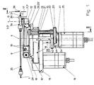
- the pivot axis 6 is in turn on bearing blocks 8 and 9 supported on an intermediate plate 10 ', and which in turn attached to a swivel platform 10.
- One swivel arm 7 ' is for adjusting the roller contact force in a perpendicular to the axis of rotation 3,3 ' the latter 2.2 'extending plane about a pivot axis 11 pivotally mounted.
- a pneumatic cylinder 12 is used for lateral pivoting of the pivoted swivel arm 7 '.
- the contact pressure is above one Pneumatic pressure regulator upstream of the pneumatic cylinder 12 (not shown) set.
- the Swivel platform 10 is along its outer circumference 13 gear-shaped and via a toothed belt 14 with a fixed in a stationary base plate 15 Stepper motor 16 connected in terms of drive, which the execution of a precisely defined swivel movement by a certain swivel angle.
- the second swivel arm 7 is only together with the first Swivel arm 7 'about the swivel axis 6 against the spring action a compression spring 40 can be pivoted downward, however cannot be swiveled to the side.
- the two transport and take-off rollers 2, 2 ' are theirs opposite synchronous drive with a gear wheel each trained drive wheel 17 or 17 'connected, to drive an endless toothed belt 18 or 18 'around this, above the boom arms 7 or 7' to the rear over the second pivot axis 6 of the latter out, and there by means of a deflection and tensioning arrangement 19 down and below the extension arms 7 or 7 ', each with a gear-shaped, over the Intermediate plate 10 'mounted on the swivel platform 10 End roller 20 or 20 'runs.
- the axes of rotation of the the latter two run parallel to the first Swivel axis 4.
- the end roller 20 ' is for driving it via a drive shaft 21 with a gear-shaped on its outer circumference trained drive wheel 22 firmly connected, which has a toothed belt 23 with a gear wheel trained output gear 24 of a stepper motor 25 drive connected is.
- the stepper motor 25 is as possible to achieve one low moment of inertia when pivoting the with it connected cable transport and swivel unit if possible arranged close to the longitudinal direction of the first pivot axis 4, and via four spacer bolts 41 with a motor mounting flange 42 connected, which in turn via the two Connecting bolts 26, 27 and 27 'and a connecting shaft 28 'together with the swivel platform 10 unit pivotable about the first pivot axis 4 connected, and this unit via the connecting shaft 28 'can be pivoted with the stationary base plate 15 connected bearing block 28 stored.
- the deflection roller 30 via a connecting shaft 32 rigid with the Deflection roller 30 'connected, and the connecting shaft 32nd via the bearing blocks 33 and 34 and the intermediate plate 10 ' supported on the swivel platform 10.
- the two deflection rollers 31 and 31 ' are in this embodiment connected to a single roller, and via two ball bearings independent of the connecting shaft 32 rotatably mounted on this.
- inlet cable guide On the cable feed side of the transport and take-off rollers 2,2 'is an opening in its cable detection area, inlet cable guide connected with a flexible guide hose 35 36 and on the cable delivery side the transport and take-off rollers 2, 2 'in their cable outlet area outlet cable routing 37 intended.
- the separation and stripping unit 38 (see FIG. 1) can as can be seen in the transport and Swivel device very close to the cable delivery point the rollers 2,2 'are arranged, i.e. to the Example with a roll diameter of 45mm in one Distance D from about 40 to 50mm.
- the position of the second pivot axis 6 is selected in such a way that when the transport and take-off rollers are lowered 2.2 'around the drive rollers connected to them 17, 17 'tensioned toothed belt 18, 18' not spanned become, but not too loose in the upper starting position are excited.
Landscapes
- Engineering & Computer Science (AREA)
- Manufacturing & Machinery (AREA)
- Forwarding And Storing Of Filamentary Material (AREA)
- Manufacturing Of Electrical Connectors (AREA)
Description
Claims (9)
- Kabeltransport- und Schwenkvorrichtung, dadurch gekennzeichnet, dass mindestens zwei zur Erfassung eines zu transportierenden Kabels (1) zusammenwirkende Transport- und Abzugsrollen (2,2'), deren Drehachsen (3,3') parallel zueinander sowie parallel zu einer gemeinsamen ersten Schwenkachse (4) verlaufen, auf je einem um eine senkrecht zur letzteren sowie parallel zu einer gemeinsamen Verbindungsgeraden (5) dieser beiden Rollen (2,2') verlaufende, direkt oder indirekt (10') auf einer Schwenkplattform (10) angeordnete zweite Schwenkachse (6) gemeinsam schwenkbaren Auslegerarm (7,7') drehbar angeordnet sind, dass mindestens die eine der beiden Transport- und Abzugsrollen (2') bezüglich ihrem Abstand (a) zur zweiten Transport- und Abzugsrolle (2) seitlich verstellbar angeordnet ist, und dass mit der Schwenkplattform (10) zusammen schwenkbar verbundene erste Antriebsmittel (25) zum zueinander synchronen, genau definierten Antrieb der beiden Transport- und Abzugsrollen (2,2'), und zweite, antriebsmässig mit der Schwenkplattform (10) verbundene Antriebsmittel (16) zur Erzielung einer genau definierten Drehbewegung der Schwenkplattform (10) um die erste Schwenkachse (4), vorgesehen sind.
- Vorrichtung nach Anspruch 1, dadurch gekennzeichnet, dass die Antriebsmittel mit über eine gemeinsame Steuerung miteinander verbundenen Schrittmotoren (16,25) versehen sind.
- Vorrichtung nach Anspruch 1 oder 2, dadurch gekennzeichnet, dass der eine Schwenkarm (7') zur Verstellung des gegenseitigen Abstandes (a) der beiden Transport- und Abzugsrollen (2,2') zueinander in einer senkrecht zur Drehachse (3,3') der letzteren verlaufenden Ebene schwenkbar gelagert und mit Verstellmitteln (12) zur Einstellung dieses Abstandes (a) und/oder Anpressdruckes verbunden ist.
- Vorrichtung nach einem der Ansprüche 1 bis 3, dadurch gekennzeichnet, dass die Schwenkplattform (10) auf ihrem Umfang (13) mit einem zahnradförmigen Profil zur antriebsmässigen Verbindung, vorzugsweise über einen Zahnriemen (14), mit den zweiten Antriebsmitteln (16), versehen ist.
- Vorrichtung nach einem der Ansprüche 1 bis 4, dadurch gekennzeichnet, dass die beiden Transport- und Abzugsrollen (2,2') mit je einem zahnradförmig ausgebildeten Antriebsrad (17,17') verbunden sind, dass zu deren Antrieb je ein endloser Zahnriemen (18,18') um diese herum, oberhalb der Auslegerarme (7,7') nach hinten über die zweite Schwenkachse (6) der letzteren hinaus, und dort mittels einer Zahnriemen-Umlenkanordnung (19) nach unten und unterhalb der Auslegerarme (7,7') in Eingriff mit je einer zahnradförmig ausgebildeten, auf der Schwenkplattform (10) gelagerten Endrolle (20,20') verläuft, wobei die Drehachsen der beiden letzteren vorzugsweise parallel zur ersten Schwenkachse (4) verlaufen, die eine dieser beiden Spannrollen (20') zu deren Antrieb mit den ersten Antriebsmitteln (25) verbunden ist, und dass die Zahnriemen-Umlenkanordnung (19) durch vier längs einer zur zweiten Schwenkachse (6) parallel verlaufenden Drehachse (33) drehbar angeordnete, zahnradförmig ausgebildete, in kämmendem Eingriff mit der gezähnten Seite der Zahnriemen (18,18') in Eingriff stehende Umlenkwalzen (30,30'; 31, 31') gebildet wird, wobei die jeweils dem einen Trum des einen Zahnriemens (18) zugeordnete Umlenkwalze (30,31) drehstarr mit der dem jeweils einen korrespondierenden Trum des anderen Zahnriemen (18') zugeordneten Umlenkwalze (30',31') verbunden ist, so dass sich zwangsweise ein synchroner Antrieb in entgegengesetztem Drehsinn der beiden Transport- und Abzugsrollen (2,2') ergibt.
- Vorrichtung nach Anspruch 5, dadurch gekennzeichnet, dass die Längsachse des Antriebsmotors (25) der ersten Antriebsmittel parallel zur ersten Schwenkachse (4) verläuft und vorzugsweise mindestens annähernd mit dieser zusammenfällt.
- Vorrichtung nach einem der Ansprüche 1 bis 6, dadurch gekennzeichnet, dass auf der Kabelzuführseite der Transport- und Abzugsrollen (2,2') eine in deren Kabelerfassungsbereich mündende, vorzugsweise mit einem biegsamen Führungsschlauch (35) verbundene Eintritts-Kabelführung (36) sowie auf der Kabelabgabeseite der Transport- und Abzugsrollen (2,2') eine in deren Kabelaustrittsbereich mündende Austritts-Kabelführung (37) vorgesehen ist, wobei die letztere vorzugsweise höchstens 10 bis 30mm lang ist.
- Vorrichtung nach einem der Ansprüche 1 bis 7, dadurch gekennzeichnet, dass die Kabelerfassungsstelle einer im Kabelabgabe-Schwenkbereich zugeordneten Kabelbearbeitungsstation (38) derart angeordnet ist, dass bei auf diese Kabelerfassungsstelle ausgerichteter Austritts-Kabelführung (37) die Austrittsmündung der letzteren höchstens 5 bis 30mm, vorzugsweise höchstens 5 bis 15mm von dieser Kabelerfassungsstelle entfernt ist.
- Vorrichtung nach einem der Ansprüche 1 bis 8 in Verbindung mit mindestens einer im Kabelabgabe-Schwenkbereich angeordneten Trenn- und Abisoliermesser-Einheit (38) und/oder einer Crimpeinheit.
Applications Claiming Priority (2)
| Application Number | Priority Date | Filing Date | Title |
|---|---|---|---|
| CH03171/94A CH689278A5 (de) | 1994-10-21 | 1994-10-21 | Kabeltransport- und Schwenkvorrichtung. |
| CH3171/94 | 1994-10-21 |
Publications (2)
| Publication Number | Publication Date |
|---|---|
| EP0708050A1 EP0708050A1 (de) | 1996-04-24 |
| EP0708050B1 true EP0708050B1 (de) | 1998-09-02 |
Family
ID=4250163
Family Applications (1)
| Application Number | Title | Priority Date | Filing Date |
|---|---|---|---|
| EP94810670A Expired - Lifetime EP0708050B1 (de) | 1994-10-21 | 1994-11-24 | Kabeltransport- und Schwenkvorrichtung |
Country Status (5)
| Country | Link |
|---|---|
| US (1) | US5601223A (de) |
| EP (1) | EP0708050B1 (de) |
| JP (1) | JP3612371B2 (de) |
| CH (1) | CH689278A5 (de) |
| DE (1) | DE59406847D1 (de) |
Cited By (1)
| Publication number | Priority date | Publication date | Assignee | Title |
|---|---|---|---|---|
| WO2009141794A2 (en) | 2008-05-20 | 2009-11-26 | Schleuniger Holding Ag | Cable transport device |
Families Citing this family (11)
| Publication number | Priority date | Publication date | Assignee | Title |
|---|---|---|---|---|
| SE508543C2 (sv) * | 1997-02-03 | 1998-10-12 | Asea Brown Boveri | Hasplingsanordning |
| US6073916A (en) * | 1998-10-08 | 2000-06-13 | Greenlee Textron Inc. | Powered cable feeding system |
| CN102195226B (zh) * | 2010-03-12 | 2014-09-03 | 库迈思控股股份公司 | 线缆供给和旋转系统 |
| PL2777053T3 (pl) | 2011-11-11 | 2016-06-30 | Schleuniger Holding Ag | Urządzenie do skręcania |
| EP2777052B1 (de) | 2011-11-11 | 2016-04-13 | Schleuniger Holding AG | Fördereinrichtung für leitungen |
| US20150008245A1 (en) | 2011-11-11 | 2015-01-08 | Schleuniger Holding Ag | Line transport device |
| JP6072054B2 (ja) | 2011-11-11 | 2017-02-01 | シュロニガー ホールディング アーゲー | ケーブル受取装置(ワイヤースタッカー) |
| PT2801984T (pt) | 2013-05-08 | 2019-01-23 | Schleuniger Holding Ag | Prendedor, cabeça de torção e dispositivo de torção |
| EP3165487A1 (de) * | 2015-11-08 | 2017-05-10 | Schleuniger Holding AG | Leitungstransportvorrichtung, insbesondere für zu bearbeitende kabel in kabelbearbeitungsmaschinen |
| CN112577821A (zh) * | 2020-12-03 | 2021-03-30 | 博硕科技(江西)有限公司 | 一种支持游戏机高清传输的数据线生产用拉伸检测装置 |
| CN112607503A (zh) * | 2020-12-03 | 2021-04-06 | 芜湖楚江合金铜材有限公司 | 一种led光源高导、光亮铜合金线材生产用牵引装置 |
Family Cites Families (11)
| Publication number | Priority date | Publication date | Assignee | Title |
|---|---|---|---|---|
| CA527616A (en) * | 1956-07-10 | Esso Research And Engineering Company | Seismograph cable handling device | |
| CA630945A (en) * | 1961-11-14 | Western Electric Company, Incorporated | Capstan drive apparatus | |
| DE1035607B (de) * | 1956-09-27 | 1958-08-07 | Hermann Boecher | Vorrichtung zum Messen und Steuern der Geschwindigkeit von geradlinig bewegtem Gut, z. B. von einem aus dem Walzgeruest auf einen Haspel auflaufenden Draht |
| US3014628A (en) * | 1959-12-07 | 1961-12-26 | Foster & Allen Inc | Pinch-roll take-off apparatus |
| US3318221A (en) * | 1965-01-29 | 1967-05-09 | Polaroid Corp | Photographic processing apparatus |
| SU458877A1 (ru) * | 1973-05-10 | 1975-01-30 | Предприятие П/Я А-3593 | Устройство дл перемещени магнитной ленты |
| US4846388A (en) * | 1985-05-17 | 1989-07-11 | Benbow Christopher B | Yarn dispensing apparatus |
| DE3606059A1 (de) * | 1986-02-25 | 1987-08-27 | Fraunhofer Ges Forschung | Werkzeug zum verlegen und ablaengen von kabeln mit hilfe eines industrieroboters |
| US5000439A (en) * | 1988-11-14 | 1991-03-19 | Canon Kabushiki Kaisha | Sheet conveying apparatus and image recording apparatus having same |
| JPH03177646A (ja) * | 1989-12-04 | 1991-08-01 | Sharp Corp | 複写機の駆動装置 |
| EP0509192A1 (de) * | 1991-04-17 | 1992-10-21 | Ttc Technology Trading Company | Einrichtung zum Trennen und Abisolieren elektrischer Kabel in einer Kabelverarbeitungsmaschine |
-
1994
- 1994-10-21 CH CH03171/94A patent/CH689278A5/de not_active IP Right Cessation
- 1994-11-24 EP EP94810670A patent/EP0708050B1/de not_active Expired - Lifetime
- 1994-11-24 DE DE59406847T patent/DE59406847D1/de not_active Expired - Lifetime
-
1995
- 1995-10-20 JP JP27298495A patent/JP3612371B2/ja not_active Expired - Fee Related
- 1995-10-23 US US08/546,596 patent/US5601223A/en not_active Expired - Lifetime
Cited By (1)
| Publication number | Priority date | Publication date | Assignee | Title |
|---|---|---|---|---|
| WO2009141794A2 (en) | 2008-05-20 | 2009-11-26 | Schleuniger Holding Ag | Cable transport device |
Also Published As
| Publication number | Publication date |
|---|---|
| JPH08255518A (ja) | 1996-10-01 |
| CH689278A5 (de) | 1999-01-29 |
| JP3612371B2 (ja) | 2005-01-19 |
| US5601223A (en) | 1997-02-11 |
| EP0708050A1 (de) | 1996-04-24 |
| DE59406847D1 (de) | 1998-10-08 |
Similar Documents
| Publication | Publication Date | Title |
|---|---|---|
| DE3243906C2 (de) | ||
| DE68904468T2 (de) | Vorrichtung zum drehen von buendeln in verwendung mit foerderern. | |
| EP0496049B1 (de) | Verbesserung an der Einrichtung zum Zubringen eines Kabels in einen Kabel-Verarbeitungsautomaten | |
| CH666441A5 (de) | Vorrichtung zum schneiden mindestens eines segmentes von einem kontinuierlichen strang. | |
| EP0598276B1 (de) | Kabelzuführungs- und -wechseleinrichtung für eine Kabelverarbeitungsmaschine | |
| EP3165487A1 (de) | Leitungstransportvorrichtung, insbesondere für zu bearbeitende kabel in kabelbearbeitungsmaschinen | |
| DE19510649A1 (de) | Transportvorrichtung | |
| EP0708050A1 (de) | Kabeltransport- und Schwenkvorrichtung | |
| DE4402560C2 (de) | Vorrichtung zum Drehen von flachliegend voranbewegten Werkstücken | |
| DE4026989A1 (de) | Drahtbiegemaschine fuer mit isolierung versehenen draht | |
| DE3209409C2 (de) | ||
| EP2143671A1 (de) | Paketierungsvorrichtung | |
| EP0755886A1 (de) | Vorrichtung zum Zubringen von Druckereiprodukten zu einer Weiterverarbeitungsstelle | |
| DE10314607A1 (de) | Drehbare Signaturentransportvorrichtung | |
| DE3873906T2 (de) | Drahtfuehrung bei einer drahterosionsbearbeitungsvorrichtung. | |
| CH696538A5 (de) | Signaturenübergabevorrichtung. | |
| EP0236688B1 (de) | Verfahren zum Wechseln von elektrischen Leitungen beim Bestücken mit elektrischen Verbindern und Vorrichtung zur Durchführung des Verfahrens | |
| EP0887295A2 (de) | Vorrichtung zum Unterteilen einer Papierbahn | |
| DE3524339C2 (de) | ||
| DE3401511C2 (de) | Verfahren und Vorrichtung zum Verschwenken von flächigen Gegenständen | |
| DE10341645B3 (de) | Längsfalzvorrichtung | |
| DE2930806C2 (de) | Vorrichtung zum Ausrichten von Gegenständen | |
| DE3135575C2 (de) | Vorrichtung zum Herstellen von Schuppenbandrollen | |
| DE10129007C1 (de) | Vorrichtung zum unterschuppten Zuführen von Bogen | |
| EP1582491B1 (de) | Vorrichtung zum Transport flächiger Werkstücke |
Legal Events
| Date | Code | Title | Description |
|---|---|---|---|
| PUAI | Public reference made under article 153(3) epc to a published international application that has entered the european phase |
Free format text: ORIGINAL CODE: 0009012 |
|
| AK | Designated contracting states |
Kind code of ref document: A1 Designated state(s): DE FR GB IT |
|
| 17P | Request for examination filed |
Effective date: 19960823 |
|
| GRAG | Despatch of communication of intention to grant |
Free format text: ORIGINAL CODE: EPIDOS AGRA |
|
| 17Q | First examination report despatched |
Effective date: 19971118 |
|
| GRAG | Despatch of communication of intention to grant |
Free format text: ORIGINAL CODE: EPIDOS AGRA |
|
| GRAG | Despatch of communication of intention to grant |
Free format text: ORIGINAL CODE: EPIDOS AGRA |
|
| GRAH | Despatch of communication of intention to grant a patent |
Free format text: ORIGINAL CODE: EPIDOS IGRA |
|
| GRAH | Despatch of communication of intention to grant a patent |
Free format text: ORIGINAL CODE: EPIDOS IGRA |
|
| RAP1 | Party data changed (applicant data changed or rights of an application transferred) |
Owner name: KOMAX HOLDING AG |
|
| GRAA | (expected) grant |
Free format text: ORIGINAL CODE: 0009210 |
|
| AK | Designated contracting states |
Kind code of ref document: B1 Designated state(s): DE FR GB IT |
|
| ITF | It: translation for a ep patent filed | ||
| REF | Corresponds to: |
Ref document number: 59406847 Country of ref document: DE Date of ref document: 19981008 |
|
| GBT | Gb: translation of ep patent filed (gb section 77(6)(a)/1977) |
Effective date: 19981008 |
|
| ET | Fr: translation filed | ||
| PLBE | No opposition filed within time limit |
Free format text: ORIGINAL CODE: 0009261 |
|
| STAA | Information on the status of an ep patent application or granted ep patent |
Free format text: STATUS: NO OPPOSITION FILED WITHIN TIME LIMIT |
|
| 26N | No opposition filed | ||
| REG | Reference to a national code |
Ref country code: GB Ref legal event code: IF02 |
|
| PGFP | Annual fee paid to national office [announced via postgrant information from national office to epo] |
Ref country code: FR Payment date: 20081113 Year of fee payment: 15 |
|
| PGFP | Annual fee paid to national office [announced via postgrant information from national office to epo] |
Ref country code: GB Payment date: 20081117 Year of fee payment: 15 |
|
| GBPC | Gb: european patent ceased through non-payment of renewal fee |
Effective date: 20091124 |
|
| REG | Reference to a national code |
Ref country code: FR Ref legal event code: ST Effective date: 20100730 |
|
| PG25 | Lapsed in a contracting state [announced via postgrant information from national office to epo] |
Ref country code: FR Free format text: LAPSE BECAUSE OF NON-PAYMENT OF DUE FEES Effective date: 20091130 |
|
| PG25 | Lapsed in a contracting state [announced via postgrant information from national office to epo] |
Ref country code: GB Free format text: LAPSE BECAUSE OF NON-PAYMENT OF DUE FEES Effective date: 20091124 |
|
| PGFP | Annual fee paid to national office [announced via postgrant information from national office to epo] |
Ref country code: DE Payment date: 20131121 Year of fee payment: 20 |
|
| PGFP | Annual fee paid to national office [announced via postgrant information from national office to epo] |
Ref country code: IT Payment date: 20131128 Year of fee payment: 20 |
|
| REG | Reference to a national code |
Ref country code: DE Ref legal event code: R071 Ref document number: 59406847 Country of ref document: DE |