EP0707970A2 - Farbstoffnachfüllvorrichtung - Google Patents
Farbstoffnachfüllvorrichtung Download PDFInfo
- Publication number
- EP0707970A2 EP0707970A2 EP95304298A EP95304298A EP0707970A2 EP 0707970 A2 EP0707970 A2 EP 0707970A2 EP 95304298 A EP95304298 A EP 95304298A EP 95304298 A EP95304298 A EP 95304298A EP 0707970 A2 EP0707970 A2 EP 0707970A2
- Authority
- EP
- European Patent Office
- Prior art keywords
- ink
- conduit
- cartridge
- support plate
- refilling assembly
- Prior art date
- Legal status (The legal status is an assumption and is not a legal conclusion. Google has not performed a legal analysis and makes no representation as to the accuracy of the status listed.)
- Granted
Links
- 230000001681 protective effect Effects 0.000 claims description 7
- 230000008878 coupling Effects 0.000 claims description 5
- 238000010168 coupling process Methods 0.000 claims description 5
- 238000005859 coupling reaction Methods 0.000 claims description 5
- 229920000742 Cotton Polymers 0.000 claims description 2
- JOYRKODLDBILNP-UHFFFAOYSA-N Ethyl urethane Chemical compound CCOC(N)=O JOYRKODLDBILNP-UHFFFAOYSA-N 0.000 claims description 2
- 239000011358 absorbing material Substances 0.000 abstract description 7
- 230000005484 gravity Effects 0.000 abstract description 6
- 239000000463 material Substances 0.000 description 7
- 229920001971 elastomer Polymers 0.000 description 4
- 239000005060 rubber Substances 0.000 description 4
- 208000027418 Wounds and injury Diseases 0.000 description 2
- 230000002745 absorbent Effects 0.000 description 2
- 239000002250 absorbent Substances 0.000 description 2
- 230000006378 damage Effects 0.000 description 2
- 208000014674 injury Diseases 0.000 description 2
- 239000004033 plastic Substances 0.000 description 2
- 229920003023 plastic Polymers 0.000 description 2
- 239000004698 Polyethylene Substances 0.000 description 1
- XAGFODPZIPBFFR-UHFFFAOYSA-N aluminium Chemical compound [Al] XAGFODPZIPBFFR-UHFFFAOYSA-N 0.000 description 1
- 229910052782 aluminium Inorganic materials 0.000 description 1
- 230000000694 effects Effects 0.000 description 1
- 239000013013 elastic material Substances 0.000 description 1
- 239000012530 fluid Substances 0.000 description 1
- 238000002347 injection Methods 0.000 description 1
- 239000007924 injection Substances 0.000 description 1
- 239000007788 liquid Substances 0.000 description 1
- 230000035515 penetration Effects 0.000 description 1
- -1 polyethylene Polymers 0.000 description 1
- 229920000573 polyethylene Polymers 0.000 description 1
- 229920005989 resin Polymers 0.000 description 1
- 239000011347 resin Substances 0.000 description 1
- 229920003051 synthetic elastomer Polymers 0.000 description 1
- 239000005061 synthetic rubber Substances 0.000 description 1
- 125000000391 vinyl group Chemical group [H]C([*])=C([H])[H] 0.000 description 1
- 229920002554 vinyl polymer Polymers 0.000 description 1
Images


Classifications
-
- B—PERFORMING OPERATIONS; TRANSPORTING
- B41—PRINTING; LINING MACHINES; TYPEWRITERS; STAMPS
- B41J—TYPEWRITERS; SELECTIVE PRINTING MECHANISMS, i.e. MECHANISMS PRINTING OTHERWISE THAN FROM A FORME; CORRECTION OF TYPOGRAPHICAL ERRORS
- B41J2/00—Typewriters or selective printing mechanisms characterised by the printing or marking process for which they are designed
- B41J2/005—Typewriters or selective printing mechanisms characterised by the printing or marking process for which they are designed characterised by bringing liquid or particles selectively into contact with a printing material
- B41J2/01—Ink jet
- B41J2/17—Ink jet characterised by ink handling
- B41J2/175—Ink supply systems ; Circuit parts therefor
- B41J2/17503—Ink cartridges
- B41J2/17506—Refilling of the cartridge
-
- B—PERFORMING OPERATIONS; TRANSPORTING
- B41—PRINTING; LINING MACHINES; TYPEWRITERS; STAMPS
- B41J—TYPEWRITERS; SELECTIVE PRINTING MECHANISMS, i.e. MECHANISMS PRINTING OTHERWISE THAN FROM A FORME; CORRECTION OF TYPOGRAPHICAL ERRORS
- B41J2/00—Typewriters or selective printing mechanisms characterised by the printing or marking process for which they are designed
- B41J2/005—Typewriters or selective printing mechanisms characterised by the printing or marking process for which they are designed characterised by bringing liquid or particles selectively into contact with a printing material
- B41J2/01—Ink jet
- B41J2/17—Ink jet characterised by ink handling
- B41J2/175—Ink supply systems ; Circuit parts therefor
- B41J2/17503—Ink cartridges
- B41J2/17536—Protection of cartridges or parts thereof, e.g. tape
Definitions
- This invention relates to an ink refilling assembly or adapter for refilling a used ink cartridge with ink.
- ink cartridges have been developed for printers which use liquid ink for printing, such as ink jet printers. Some of the ink cartridges are disposed of once the ink contained in the cartridges has been depleted. Other ink cartridges may be refilled with ink when ink contained in the cartridges has been depleted.
- a refillable ink cartridge has an inlet port which may be closed by a plug or a cap.
- a syringe with a needle-like injector may be used to transport ink from a separate ink container into the refillable ink cartridge through the inlet port.
- a separate ink container may include an injection nozzle which is attached to the container so that ink can be directly supplied from the container to the refillable ink cartridge.
- an ink refilling assembly for refilling an ink cartridge with ink from a separate ink container
- the ink refilling assembly is mainly comprised of a covering plate that is snugly placed on an ink cartridge.
- the cover plate may be provided with a conduit defining an upper portion and a lower portion which is opposite from the upper portion so that the conduit penetrates the covering plate.
- the covering plate may have a protective collar surrounding the upper portion of the conduit, and a cap which has an ink absorbing material in it is put on the protective collar.
- the ink refilling assembly may further have an air room under the covering plate, and the lower portion of the conduit may have substantially a D configuration in cross section so as to form an air passage between the conduit and an ink inlet of the ink cartridge.
- the ink refilling assembly when the ink refilling assembly is set between the ink container and the ink cartridge in a fully engaged position, the first end and the second end of the conduit extend into the ink container and the ink cartridge, respectively, thus allowing the ink in the ink container to flow from the container into the ink cartridge by gravity.
- the air inside the cartridge can escape smoothly from the cartridge as the ink flows down by gravity into the cartridge.
- the cap put on the protective collar after the completion of the refilling of the ink the ink absorbent material in the cap absorbs the ink remaining inside and outside of the conduit, thus preventing the ink from being transferred from the conduit to surrounding areas.
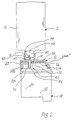
- the ink refilling assembly or the ink refill adapter in accordance with one embodiment of the present invention is generally indicated at numeral 10.
- the ink refilling assembly 10 is placed between an ink container 12 and a used, empty ink cartridge 14 and adapted to provide a fluid coupling between the ink container 12 and the ink cartridge 14 through a conduit 28 provided in the refilling assembly 10.
- the ink refilling assembly 10 is fully engaged with the ink container 12 and the ink cartridge 14 as shown in Fig. 2, the ink in the ink container 12 flows into the cartridge 14 by its own weight or by gravity.
- the ink container 12 may be made of a suitable plastic material or a rubber. As shown in Fig. 2, the container 12 may be preferably formed from a bag 16 with a neck portion 18 extending outwardly from the bag 16.
- the bag 16 is made of a relatively soft pliable material, such as aluminum, well-plasticized vinyl resins or soft polyethylene.
- the ink flows into the cartridge 14 by gravity and therefore there is no need to squeeze the bag 16. Accordingly, the bag 16 can be made of a hard material too.
- the neck portion 18 may be made of a relatively hard material regardless of the material of the bag 16 in terms of hardness (or softness).
- the neck portion 18 of the container 12 defines a central outlet port 20 and includes a plug 22 for closing the outlet port 20.
- the plug 22 is preferably made of a relatively soft and flexible materials such as rubber or a synthetic rubber.
- the ink cartridge 14, with which the ink refilling assembly 10 embodying the present invention is used has a round ink inlet 42 in the top wall 26.
- the lower portion of the conduit 28 has a length that extends through the ink inlet 42 of the ink cartridge 14 when the ink refilling assembly 10 is placed on the ink cartridge 14. More specifically, the ink inlet 42 of the cartridge 14 is closed by a ball plug 43 that is snap fitted in the ink inlet 42 but is removed by the lower end of the conduit 28 when the lower end pushes it down.
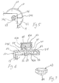
- the ink refilling assembly 10 embodying the present invention is made of a support plate 24 and the conduit 28 which passes through the support plate 24 at an angle transverse to the support plate 24.
- the conduit 28 has an upper portion 34 and a lower portion 36.
- the support plate 24 generally sits on the top wall 26 of the ink cartridge 14 when the ink refilling assembly 10 is fully engaged with the ink cartridge 14. So as to accomplish such a full engagement, the support plate 24 is shaped so as to conform to the shape of the top wall 26 of the ink cartridge 14 so that it is snugly placed on the cartridge 14.
- the support plate 24 defines an upper surface 30 which is adapted to come in contact with the neck portion 18 of the ink container 12 and a lower surface 32 which is adapted to be positioned over the top wall 26 of the ink cartridge 14.
- the support plate 24 is in a shape which conforms to the shape of the top wall 26 and upper edges of the side walls 33a and 33b of the ink cartridge 14. This feature is to stabilize the ink refilling assembly 10 with respect to the ink cartridge 14 during the ink refilling operation.
- the support plate 24 has four side walls 24a.
- the side walls 24a extend at right angles (except for the one 24a' locating front side of the assembly 10) from the edges of the support plate 24 and surround the lower surface 32 of the support plate 24, thus defining an inner space 24b.
- the side walls 24a are provided with a plurality of ribs 24c that project inwardly towards the inner space 24b from the inner surfaces of the side walls 24a.
- the ribs 24b extend in the direction parallel to the lower portion 36 of the conduit 28. With these ribs 24c, air spaces 60 are formed as shown in Fig. 4 between the ink cartridge 14, through which the air can escape from the cartridge 14, and the ink refilling assembly 10 when the ink refilling assembly 10 is placed on the cartridge 14.
- the inner space 24b of the ink refilling assembly 10 is divided into two sections: a deeper section 24b' and a shallow section 24b''.
- the shallow section 24b'' has a depth in which the lower surface 32 of the support plate 24 that positionally corresponds to the shallow section 24b'' comes into contact with the top surface of the cartridge 14 when the ink refilling assembly 10 is placed on the ink cartridge 14; however, the deep section 24b' has a depth in which the lower surface 32 of the support plate 24 that positionally corresponds to the deeper section 24b' does not come into contact with and keeps a distance from the top surface of the cartridge 14, thus forming an air room 62 therebetween (see Fig. 6).
- the upper portion 34 of the conduit 28 extends from the upper surface 30 of the support plate 24 and the lower portion 36 of the conduit 28 extends from the lower surface 32 of the support plate 24.
- the upper portion 34 of the conduit 28 has a sharp pointed end 38.
- the upper portion 34 of the conduit 28 has a sufficient length so that the upper portion 34 penetrates through the plug 22 and the pointed end 38 extends into a reserve of ink in the ink container 12.
- the plug 22 is made of a relatively elastic material such as rubber. Therefore, when the upper portion 34 of the conduit 23 penetrates through the plug 22, a hole thus formed in the plug 22 by the upper portion 34 of the conduit 28 is elastically sealed by the elasticity of the plug 22. On the other hand, when the upper portion 34 of the conduit 28 is separated from the plug 22, the hole extending through the plug 22 is sealed by its own elasticity of the plug 22. As a result, substantially no ink spillage occurs during and after the ink refilling operation.
- the lower portion 36 of the conduit 28 is round in cross section, but it can be shaped into a D in horizontal cross section as shown in the embodiment of Fig. 3. More specifically, in this embodiment, the lower portion 36 of the conduit 28 has a flat surface 36a on the outer circumference.
- the flat surface 36a extends along the axis of the conduit 28 so that the flat surface 36a forms the lower portion 36 into a D shaped cross section.
- the conduit 28 forms, as shown in Fig. 5, an air passage 38 between the lower portion 36 of the conduit 28 and the round ink refill hole 42 of the cartridge 14 so that the air passage 38 opens into the air room 62.
- the air inside the cartridge 14 can flow out of the cartridge 14 into the air room 62 through the air passage 38 and further to the outside of the ink refilling assembly 10 via the air spaces 60.
- the ink refilling assembly 10 further includes a guide collar 40 on the upper surface 30.
- the guide collar 40 surrounds the upper portion 34 of the conduit 28 with a space in between.
- the guide collar 40 is slightly higher than the upper portion 34 of the conduit 28.
- the neck portion 18 of the container 12 is easily guided towards the support plate 24 and to the conduit 28 and also any injury to fingers of the user can be prohibited.
- the upper portion 34 of the conduit 28 and the guide collar 40 extend at an angle substantially perpendicular to the upper surface 30 of the support plate 24. This arrangement stabilizes and facilitates the penetration of the upper portion 34 of the conduit 28 into the plug 22 of the ink container 12.
- the guide collar 40 can be covered by a safety cap 42 as shown in Fig. 6.
- the safety cap 42 as seen in Figure 7, is substantially a flat cylinder having a top 42a and a side wall 42b.
- the cap 42 is provided with an ink absorbing material or ink absorbing means 44 secured to the under surface of the top 42a.
- the ink absorbing material 44 is a cotton, urethane, etc. which is hardened and shaped into, for example, a cubic, cylinder or rectangular form.
- the ink absorbing material 44 has a sufficient thickness that can cover the upper portion 34 of the conduit 28.
- the ink absorbing material 44 has a thickness that can cover about the upper half to two thirds of the upper portion 34 of the conduit 28 so that the upper portion 34 can penetrate into the ink absorbent means 44 when the cap 42 is put on the guide collar 40.
- the ink refilling assembly 10 with the safety cap 42 thereon is placed on the ink cartridge 14.
- the refilling assembly 10 which is shaped so as to conform to the shape of the top wall of the cartridge 14 is thus snugly placed, an extreme end 46 of the lower portion 36 of the conduit 28 comes in contact with the ball plug 43 installed in the ink inlet 42 of the cartridge 14 and pushes the plug 43 down so that the ball plug 43 falls into the ink cartridge 14.
- the safety cap 42 is removed from the guide collar 40, and the ink container 12 is set as shown in Fig. 2 with the neck portion 18 inserted inside the guide collar 40.
- the ink container 12 communicates with the ink cartridge 14 via the conduit 28.
- the ink inside the ink container 12 flows down into the cartridge 14 through the conduit 28 via gravity.
- the air inside the cartridge 14 escapes outside of the cartridge 14 through the air passage 38 that is between the flat surface 36a of the lower portion 36 of the conduit and the ink inlet 46.
- ink can flow into the cartridge 14 smoothly from the ink container 12.
- the thus escaped air flows out to the air room 62 and further to outside of the ink refilling assembly 10 through the air spaces 60 that are formed by the ribs 14a between the outer surface of the ink cartridge 14 and the inner surfaces of the side walls 24a of the ink refilling assembly 10. This further helps the ink to be transferred smoothly from the ink container 12 to the cartridge 14.
- the ink container 12 is removed from the ink refilling assembly 10 and the ink inlet 42 is closed by another plug 43, such as a plastic plug or rubber plug.
- the safety cap 42 is put on the protective collar 40 so that the upper portion 34 of the conduit 18 sticks into the ink absorbing means 44.
- the ink remaining inside and outside of the upper portion 34 of the conduit 18 is absorbed by the ink absorbing means 44, thus preventing the ink from touching the desk, sleeve of a shirt of the user, etc.
Landscapes
- Ink Jet (AREA)
- Photographic Developing Apparatuses (AREA)
- Formation And Processing Of Food Products (AREA)
- Non-Silver Salt Photosensitive Materials And Non-Silver Salt Photography (AREA)
- Pens And Brushes (AREA)
Applications Claiming Priority (4)
| Application Number | Priority Date | Filing Date | Title |
|---|---|---|---|
| US32728094A | 1994-10-21 | 1994-10-21 | |
| US327280 | 1994-10-21 | ||
| US08/409,012 US5595223A (en) | 1994-10-21 | 1995-03-23 | Ink refilling assembly |
| US409012 | 1995-03-23 |
Publications (3)
| Publication Number | Publication Date |
|---|---|
| EP0707970A2 true EP0707970A2 (de) | 1996-04-24 |
| EP0707970A3 EP0707970A3 (de) | 1996-07-24 |
| EP0707970B1 EP0707970B1 (de) | 1998-04-22 |
Family
ID=26985792
Family Applications (1)
| Application Number | Title | Priority Date | Filing Date |
|---|---|---|---|
| EP95304298A Expired - Lifetime EP0707970B1 (de) | 1994-10-21 | 1995-06-20 | Farbstoffnachfüllvorrichtung |
Country Status (5)
| Country | Link |
|---|---|
| US (1) | US5595223A (de) |
| EP (1) | EP0707970B1 (de) |
| AT (1) | ATE165278T1 (de) |
| DE (2) | DE707970T1 (de) |
| HK (1) | HK1007236A1 (de) |
Cited By (12)
| Publication number | Priority date | Publication date | Assignee | Title |
|---|---|---|---|---|
| WO1997045269A1 (en) * | 1996-05-29 | 1997-12-04 | Dataproducts Corporation | Ink jet printer cartridge refilling method and apparatus |
| EP0841171A3 (de) * | 1996-11-07 | 1998-08-12 | Laser Care Modul Recycling GmbH | Tintennachfüllpatrone für Tintenstrahldrucker |
| EP0816099A3 (de) * | 1996-06-28 | 1999-03-17 | Mitsubishi Pencil Corporation of America | Farbstoffnachfüllvorrichtung |
| EP0884187A3 (de) * | 1997-06-12 | 2000-03-29 | Mitsubishi Pencil Corporation of America | Vorrichtung zur Herstellung eines Loches in einer Tintenkassette |
| US6120138A (en) * | 1997-05-12 | 2000-09-19 | Hana Company Limited | Refill assembly for printer ink cartridges |
| US6695495B1 (en) | 2003-03-12 | 2004-02-24 | Printronix, Inc. | Constant density printer system |
| US6896429B2 (en) | 2003-03-12 | 2005-05-24 | Printronix, Inc. | Constant density printer system |
| WO2005110763A1 (en) * | 2004-05-13 | 2005-11-24 | Paul Geldenhuys | Ink supply system for a printer |
| WO2009103422A1 (de) * | 2008-02-22 | 2009-08-27 | Pelikan Hardcopy Production Ag | Vorrichtung zur wiederbefüllung einer tintenpatrone für einen tintenstrahldrucker |
| EP4253073A3 (de) * | 2016-06-10 | 2024-01-10 | Seiko Epson Corporation | Tintennachfüllbehälter und tintennachfüllsystem |
| US11932022B2 (en) | 2017-01-26 | 2024-03-19 | Seiko Epson Corporation | Ink bottle and bottle set |
| US11938739B2 (en) | 2016-06-10 | 2024-03-26 | Seiko Epson Corporation | Ink refill container, ink refill system, and ink refill adapter |
Families Citing this family (42)
| Publication number | Priority date | Publication date | Assignee | Title |
|---|---|---|---|---|
| US6305769B1 (en) | 1995-09-27 | 2001-10-23 | 3D Systems, Inc. | Selective deposition modeling system and method |
| US5838352A (en) * | 1995-11-24 | 1998-11-17 | Smith Corona Corporation | Ink cartridge refilling device and station for cartridges and gravity feed ink bottle |
| US5933173A (en) * | 1996-03-22 | 1999-08-03 | Olivetti Lexikon S.P.A. | Holder for refilling and preserving an ink jet printhead |
| USD390598S (en) | 1996-03-26 | 1998-02-10 | Seiko Epson Corporation | Ink cartridge for printer |
| USD389180S (en) | 1996-03-26 | 1998-01-13 | Seiko Epson Corporation | Ink cartridge for printer |
| USD387801S (en) * | 1996-03-26 | 1997-12-16 | Seiko Epson Corporation | Ink cartridge for printer |
| USD390261S (en) | 1996-03-26 | 1998-02-03 | Seiko Epson Corporation | Ink for cartridge for printer |
| KR0174704B1 (ko) * | 1996-03-29 | 1999-05-15 | 김광호 | 잉크-젯 프린터의 칼라-잉크 재충전 장치 |
| US5845682A (en) * | 1996-06-28 | 1998-12-08 | Mitsubishi Pencil Corporation Of America | Apparatus for refilling an ink cartridge |
| AU129937S (en) | 1996-07-12 | 1997-05-12 | Fullmark Private Ltd | Refill device for ink jet cartridges |
| US6053603A (en) * | 1997-08-27 | 2000-04-25 | Mitsubishi Pencil Corporation Of America | Device and method for refilling an ink cartridge |
| KR100490387B1 (ko) * | 1998-01-31 | 2005-08-04 | 삼성전자주식회사 | 인쇄기용 잉크 리필장치 |
| US5996844A (en) * | 1998-02-09 | 1999-12-07 | Mitsubishi Pencil Corporation Of America | Dispensing container for liquid |
| US6006388A (en) * | 1998-04-14 | 1999-12-28 | Young; Cecil Blake | Dispenser for dispensing concentrated liquid soap to industrial cleaning apparatuses |
| US6138693A (en) * | 1998-11-23 | 2000-10-31 | Matz; Warren W. | Automatic detergent dispenser |
| TWI227815B (en) * | 1998-12-22 | 2005-02-11 | Ricoh Kk | Toner container and image forming method and apparatus using the same |
| US6056395A (en) * | 1998-12-22 | 2000-05-02 | Liu; Win-Yin | Device to prevent from ink interruption in a printing head of an ink cartridge in a printer |
| DE19912620A1 (de) | 1999-03-22 | 2000-10-05 | Staedtler Fa J S | Vorrichtung und Anordnung zum Befüllen eines Tintentanks |
| US6227663B1 (en) * | 2000-01-05 | 2001-05-08 | Hewlett-Packard Company | Ink-jet print cartridge having a low profile |
| CN1900837B (zh) | 2000-02-17 | 2012-10-03 | 株式会社理光 | 墨粉收纳容器、补给墨粉的方法及墨粉补给装置 |
| US6619509B2 (en) | 2000-04-10 | 2003-09-16 | The Dial Corporation | Liquid dispenser |
| ES2295182T3 (es) * | 2000-07-18 | 2008-04-16 | Coloplast A/S | Un aposito. |
| JP3958511B2 (ja) * | 2000-09-28 | 2007-08-15 | 株式会社リコー | トナー補給装置および画像形成装置 |
| US6665508B2 (en) * | 2001-01-31 | 2003-12-16 | Ricoh Company, Ltd. | Toner container and image forming apparatus using the same |
| DE10116429B4 (de) | 2001-04-02 | 2005-03-24 | J. S. Staedtler Gmbh & Co. Kg | Vorrichtung zum Befüllen eines Tintentanks |
| JP4143325B2 (ja) * | 2002-04-26 | 2008-09-03 | キヤノン株式会社 | トナー補給容器及び駆動伝達部材 |
| US20050088496A1 (en) * | 2003-10-22 | 2005-04-28 | Lui Pui K. | Ink refilling cap |
| US7300138B2 (en) * | 2004-01-08 | 2007-11-27 | Eastman Kodak Company | Replaceable ink container for inkjet printer |
| WO2005087058A1 (es) * | 2004-03-12 | 2005-09-22 | Perez Ordonez Alejandro | Jarra con dispositivo para toma de agua |
| WO2006085737A1 (es) * | 2005-02-10 | 2006-08-17 | Perez Ordonez Alejandro | Sistema despachador de agua purificada |
| USD586848S1 (en) * | 2006-12-12 | 2009-02-17 | Pelikan Hardcopy Production Ag | Accessory for ink-jet printer cartridges |
| TW201029852A (en) * | 2009-02-11 | 2010-08-16 | Jetbest Corp | Continuous ink supplying system |
| JP5760399B2 (ja) | 2010-11-16 | 2015-08-12 | セイコーエプソン株式会社 | 液体補充容器 |
| US9493008B2 (en) * | 2013-03-20 | 2016-11-15 | Hewlett-Packard Development Company, L.P. | Printhead assembly with fluid interconnect cover |
| JP6294033B2 (ja) * | 2013-08-30 | 2018-03-14 | 株式会社日立産機システム | 液体容器及びそれを備えたインクジェット記録装置 |
| KR101493035B1 (ko) * | 2014-07-24 | 2015-02-17 | 주식회사 우심시스템 | 사용자가 스스로 잉크 충전 가능한 잉크젯 프린터용 잉크 카트리지 |
| US20160271613A1 (en) * | 2015-03-19 | 2016-09-22 | Biomedical Polymers, Inc. | Molded plastic needle stick accident prevention dispenser |
| CA2977506A1 (en) | 2016-08-30 | 2018-02-28 | Wal-Mart Stores, Inc. | Dry eraser and associated systems and methods |
| CA2977509C (en) * | 2016-08-30 | 2021-08-03 | Wal-Mart Stores, Inc. | Dry eraser and associated systems and methods |
| CN208180537U (zh) * | 2017-03-27 | 2018-12-04 | 精工爱普生株式会社 | 墨水补给辅助装置以及墨水补给装置 |
| JP2019084766A (ja) * | 2017-11-08 | 2019-06-06 | セイコーエプソン株式会社 | インク収容ボトル |
| CN109228697A (zh) * | 2018-09-12 | 2019-01-18 | 留丹翠 | 墨盒定位吹灰装置和打印机墨盒灌墨设备 |
Family Cites Families (21)
| Publication number | Priority date | Publication date | Assignee | Title |
|---|---|---|---|---|
| US2577045A (en) * | 1951-01-12 | 1951-12-04 | Cornelius B Stout | Gas inhaler applicator |
| US3364930A (en) * | 1965-06-11 | 1968-01-23 | Abbott Lab | Sterile venoclysis apparatus and recipient set for use therwith |
| US3764796A (en) * | 1972-10-05 | 1973-10-09 | Us Navy | Chemical lighting device |
| US4119128A (en) * | 1977-02-18 | 1978-10-10 | Marilyn Bishop | Tamperproof sterile port cover and method of making same |
| US4183684A (en) * | 1977-11-29 | 1980-01-15 | Marion Health & Safety, Inc. | Fluid dispensing unit |
| US4161178A (en) * | 1977-12-08 | 1979-07-17 | Abbott Laboratories | Additive transfer device |
| US4528268A (en) * | 1981-12-31 | 1985-07-09 | H. W. Andersen Products Inc. | Apparatus and method for testing the sufficiency of sterilization |
| JPS59131837U (ja) * | 1983-02-23 | 1984-09-04 | シャープ株式会社 | インクジエツトプリンタのインクカ−トリツジ装置 |
| JPS59156756A (ja) * | 1983-02-25 | 1984-09-06 | Ricoh Co Ltd | インクカ−トリツジ装填装置 |
| US4591875A (en) * | 1985-04-12 | 1986-05-27 | Eastman Kodak Company | Ink cartridge and cooperative continuous ink jet printing apparatus |
| JPS61284445A (ja) * | 1985-06-11 | 1986-12-15 | Nec Corp | インクジエツトプリンタのインクタンク装置 |
| US4999652A (en) * | 1987-12-21 | 1991-03-12 | Hewlett-Packard Company | Ink supply apparatus for rapidly coupling and decoupling a remote ink source to a disposable ink jet pen |
| US5222530A (en) * | 1988-10-14 | 1993-06-29 | Elkay Manufacturing Company | Hygienic cap and liquid dispensing system |
| GB9103291D0 (en) * | 1991-02-15 | 1991-04-03 | Waverley Pharma Ltd | Transfer adaptor |
| US5280300A (en) * | 1991-08-27 | 1994-01-18 | Hewlett-Packard Company | Method and apparatus for replenishing an ink cartridge |
| AU1812392A (en) * | 1991-07-12 | 1993-01-14 | Minnesota Mining And Manufacturing Company | Bottle keying system |
| GB9205870D0 (en) * | 1992-03-18 | 1992-04-29 | Willett Int Ltd | Replenishment of reservoirs |
| US5329294A (en) * | 1992-09-24 | 1994-07-12 | Repeat-O-Type Mfg. Co., Inc. | User refillable ink jet cartridge and method for making said cartridge |
| US5288159A (en) * | 1992-12-04 | 1994-02-22 | Minnesota Mining And Manufacturing Company | Liquid applicator with frangible ampoule and support |
| JP3222294B2 (ja) * | 1993-01-01 | 2001-10-22 | キヤノン株式会社 | インク再充填容器及び該容器を用いたインク再充填方法 |
| JP3077476B2 (ja) * | 1993-02-17 | 2000-08-14 | セイコーエプソン株式会社 | トラクタおよびこのトラクタを用いた連続用紙送り機構 |
-
1995
- 1995-03-23 US US08/409,012 patent/US5595223A/en not_active Expired - Fee Related
- 1995-06-20 AT AT95304298T patent/ATE165278T1/de not_active IP Right Cessation
- 1995-06-20 DE DE0707970T patent/DE707970T1/de active Pending
- 1995-06-20 DE DE69502159T patent/DE69502159T2/de not_active Expired - Fee Related
- 1995-06-20 EP EP95304298A patent/EP0707970B1/de not_active Expired - Lifetime
-
1998
- 1998-06-24 HK HK98106355A patent/HK1007236A1/en not_active IP Right Cessation
Non-Patent Citations (1)
| Title |
|---|
| None |
Cited By (15)
| Publication number | Priority date | Publication date | Assignee | Title |
|---|---|---|---|---|
| WO1997045269A1 (en) * | 1996-05-29 | 1997-12-04 | Dataproducts Corporation | Ink jet printer cartridge refilling method and apparatus |
| EP0816099A3 (de) * | 1996-06-28 | 1999-03-17 | Mitsubishi Pencil Corporation of America | Farbstoffnachfüllvorrichtung |
| EP0841171A3 (de) * | 1996-11-07 | 1998-08-12 | Laser Care Modul Recycling GmbH | Tintennachfüllpatrone für Tintenstrahldrucker |
| US6120138A (en) * | 1997-05-12 | 2000-09-19 | Hana Company Limited | Refill assembly for printer ink cartridges |
| EP0884187A3 (de) * | 1997-06-12 | 2000-03-29 | Mitsubishi Pencil Corporation of America | Vorrichtung zur Herstellung eines Loches in einer Tintenkassette |
| US6896429B2 (en) | 2003-03-12 | 2005-05-24 | Printronix, Inc. | Constant density printer system |
| US6695495B1 (en) | 2003-03-12 | 2004-02-24 | Printronix, Inc. | Constant density printer system |
| WO2005110763A1 (en) * | 2004-05-13 | 2005-11-24 | Paul Geldenhuys | Ink supply system for a printer |
| WO2009103422A1 (de) * | 2008-02-22 | 2009-08-27 | Pelikan Hardcopy Production Ag | Vorrichtung zur wiederbefüllung einer tintenpatrone für einen tintenstrahldrucker |
| EP4253073A3 (de) * | 2016-06-10 | 2024-01-10 | Seiko Epson Corporation | Tintennachfüllbehälter und tintennachfüllsystem |
| US11926162B2 (en) | 2016-06-10 | 2024-03-12 | Seiko Epson Corporation | Ink refill container and ink refill system |
| US11938739B2 (en) | 2016-06-10 | 2024-03-26 | Seiko Epson Corporation | Ink refill container, ink refill system, and ink refill adapter |
| US12280601B2 (en) | 2016-06-10 | 2025-04-22 | Seiko Epson Corporation | Ink refill container and ink refill system |
| US12296600B2 (en) | 2016-06-10 | 2025-05-13 | Seiko Epson Corporation | Ink refill container, ink refill system, and ink refill adapter |
| US11932022B2 (en) | 2017-01-26 | 2024-03-19 | Seiko Epson Corporation | Ink bottle and bottle set |
Also Published As
| Publication number | Publication date |
|---|---|
| DE69502159T2 (de) | 1998-08-13 |
| HK1007236A1 (en) | 1999-04-01 |
| EP0707970A3 (de) | 1996-07-24 |
| US5595223A (en) | 1997-01-21 |
| DE69502159D1 (de) | 1998-05-28 |
| ATE165278T1 (de) | 1998-05-15 |
| DE707970T1 (de) | 1997-04-10 |
| EP0707970B1 (de) | 1998-04-22 |
Similar Documents
| Publication | Publication Date | Title |
|---|---|---|
| EP0707970B1 (de) | Farbstoffnachfüllvorrichtung | |
| HK1007236B (en) | Ink refilling assembly | |
| US6338552B1 (en) | Ink refilling method and apparatus, ink container refilled therewith and ink jet apparatus comprising ink refilling apparatus | |
| US5944228A (en) | Thermoplastic closure for a fluid container and system for refilling a fluid reservoir | |
| US6158852A (en) | Ink refilling method and apparatus for ink cartridge | |
| EP0262292B1 (de) | Tintenversorgungssysteme | |
| EP2552708A2 (de) | Nachfüllsystem und -verfahren | |
| JP3005966U (ja) | インクジェット・カートリッジ再充填用インク注入器具 | |
| JP2688324B2 (ja) | 後充填可能な水性筆記具並びに所属の後充填容器 | |
| US20090040281A1 (en) | Device for refilling an ink cartridge for an inkjet printer | |
| US5883652A (en) | Device for filling up a container with fluid | |
| JP2958001B2 (ja) | インクカートリッジのインク補充装置及びインク補充方法 | |
| US5406991A (en) | Plastic filler insert for a writing fluid converter | |
| CN101573238A (zh) | 用于再填充喷墨打印机用墨盒的装置 | |
| US5980029A (en) | Ink refilling assembly | |
| KR101587997B1 (ko) | 연속필기 가능한 마커펜 | |
| JP2725281B2 (ja) | インク回収容器 | |
| US5642144A (en) | Rechargeable pen for printer | |
| US7104639B2 (en) | Apparatus for refilling ink cartridges | |
| WO2011035575A1 (zh) | 注液笔 | |
| JP3813663B2 (ja) | インク注入具 | |
| JPH09131886A (ja) | インク記録ヘッド用インクタンクのインク再充填装置 | |
| KR970004524Y1 (ko) | 잉크젯트 프린터용 잉크 재충전 키트(kit) | |
| JPH0867012A (ja) | インク充填器 | |
| KR970069344A (ko) | 잉크제트 프린터의 카트리지 재 충전장치 |
Legal Events
| Date | Code | Title | Description |
|---|---|---|---|
| PUAI | Public reference made under article 153(3) epc to a published international application that has entered the european phase |
Free format text: ORIGINAL CODE: 0009012 |
|
| AK | Designated contracting states |
Kind code of ref document: A2 Designated state(s): AT BE CH DE DK ES FR GB GR IE IT LI LU MC NL PT SE |
|
| PUAL | Search report despatched |
Free format text: ORIGINAL CODE: 0009013 |
|
| AK | Designated contracting states |
Kind code of ref document: A3 Designated state(s): AT BE CH DE DK ES FR GB GR IE IT LI LU MC NL PT SE |
|
| 17P | Request for examination filed |
Effective date: 19960806 |
|
| RAP1 | Party data changed (applicant data changed or rights of an application transferred) |
Owner name: MITSUBISHI PENCIL CORPORATION OF AMERICA |
|
| DET | De: translation of patent claims | ||
| 17Q | First examination report despatched |
Effective date: 19970506 |
|
| GRAG | Despatch of communication of intention to grant |
Free format text: ORIGINAL CODE: EPIDOS AGRA |
|
| GRAG | Despatch of communication of intention to grant |
Free format text: ORIGINAL CODE: EPIDOS AGRA |
|
| GRAH | Despatch of communication of intention to grant a patent |
Free format text: ORIGINAL CODE: EPIDOS IGRA |
|
| GRAH | Despatch of communication of intention to grant a patent |
Free format text: ORIGINAL CODE: EPIDOS IGRA |
|
| GRAA | (expected) grant |
Free format text: ORIGINAL CODE: 0009210 |
|
| AK | Designated contracting states |
Kind code of ref document: B1 Designated state(s): AT BE CH DE DK ES FR GB GR IE IT LI LU MC NL PT SE |
|
| PG25 | Lapsed in a contracting state [announced via postgrant information from national office to epo] |
Ref country code: NL Free format text: LAPSE BECAUSE OF FAILURE TO SUBMIT A TRANSLATION OF THE DESCRIPTION OR TO PAY THE FEE WITHIN THE PRESCRIBED TIME-LIMIT Effective date: 19980422 Ref country code: GR Free format text: LAPSE BECAUSE OF FAILURE TO SUBMIT A TRANSLATION OF THE DESCRIPTION OR TO PAY THE FEE WITHIN THE PRESCRIBED TIME-LIMIT Effective date: 19980422 Ref country code: ES Free format text: THE PATENT HAS BEEN ANNULLED BY A DECISION OF A NATIONAL AUTHORITY Effective date: 19980422 Ref country code: AT Free format text: LAPSE BECAUSE OF FAILURE TO SUBMIT A TRANSLATION OF THE DESCRIPTION OR TO PAY THE FEE WITHIN THE PRESCRIBED TIME-LIMIT Effective date: 19980422 |
|
| REF | Corresponds to: |
Ref document number: 165278 Country of ref document: AT Date of ref document: 19980515 Kind code of ref document: T |
|
| ITF | It: translation for a ep patent filed | ||
| REG | Reference to a national code |
Ref country code: CH Ref legal event code: NV Representative=s name: BOVARD AG PATENTANWAELTE Ref country code: CH Ref legal event code: EP |
|
| REF | Corresponds to: |
Ref document number: 69502159 Country of ref document: DE Date of ref document: 19980528 |
|
| ET | Fr: translation filed | ||
| PG25 | Lapsed in a contracting state [announced via postgrant information from national office to epo] |
Ref country code: LU Free format text: LAPSE BECAUSE OF NON-PAYMENT OF DUE FEES Effective date: 19980620 |
|
| PG25 | Lapsed in a contracting state [announced via postgrant information from national office to epo] |
Ref country code: IE Free format text: LAPSE BECAUSE OF NON-PAYMENT OF DUE FEES Effective date: 19980622 |
|
| PG25 | Lapsed in a contracting state [announced via postgrant information from national office to epo] |
Ref country code: SE Free format text: LAPSE BECAUSE OF FAILURE TO SUBMIT A TRANSLATION OF THE DESCRIPTION OR TO PAY THE FEE WITHIN THE PRESCRIBED TIME-LIMIT Effective date: 19980722 Ref country code: PT Free format text: LAPSE BECAUSE OF FAILURE TO SUBMIT A TRANSLATION OF THE DESCRIPTION OR TO PAY THE FEE WITHIN THE PRESCRIBED TIME-LIMIT Effective date: 19980722 Ref country code: DK Free format text: LAPSE BECAUSE OF FAILURE TO SUBMIT A TRANSLATION OF THE DESCRIPTION OR TO PAY THE FEE WITHIN THE PRESCRIBED TIME-LIMIT Effective date: 19980722 |
|
| REG | Reference to a national code |
Ref country code: IE Ref legal event code: FG4D Free format text: 79994 |
|
| NLV1 | Nl: lapsed or annulled due to failure to fulfill the requirements of art. 29p and 29m of the patents act | ||
| PG25 | Lapsed in a contracting state [announced via postgrant information from national office to epo] |
Ref country code: MC Free format text: LAPSE BECAUSE OF NON-PAYMENT OF DUE FEES Effective date: 19981231 |
|
| PLBE | No opposition filed within time limit |
Free format text: ORIGINAL CODE: 0009261 |
|
| STAA | Information on the status of an ep patent application or granted ep patent |
Free format text: STATUS: NO OPPOSITION FILED WITHIN TIME LIMIT |
|
| 26N | No opposition filed | ||
| REG | Reference to a national code |
Ref country code: GB Ref legal event code: IF02 |
|
| PGFP | Annual fee paid to national office [announced via postgrant information from national office to epo] |
Ref country code: GB Payment date: 20020625 Year of fee payment: 8 |
|
| PGFP | Annual fee paid to national office [announced via postgrant information from national office to epo] |
Ref country code: FR Payment date: 20020626 Year of fee payment: 8 |
|
| PGFP | Annual fee paid to national office [announced via postgrant information from national office to epo] |
Ref country code: DE Payment date: 20020628 Year of fee payment: 8 Ref country code: CH Payment date: 20020628 Year of fee payment: 8 |
|
| PGFP | Annual fee paid to national office [announced via postgrant information from national office to epo] |
Ref country code: BE Payment date: 20020705 Year of fee payment: 8 |
|
| PG25 | Lapsed in a contracting state [announced via postgrant information from national office to epo] |
Ref country code: GB Free format text: LAPSE BECAUSE OF NON-PAYMENT OF DUE FEES Effective date: 20030620 |
|
| PG25 | Lapsed in a contracting state [announced via postgrant information from national office to epo] |
Ref country code: LI Free format text: LAPSE BECAUSE OF NON-PAYMENT OF DUE FEES Effective date: 20030630 Ref country code: CH Free format text: LAPSE BECAUSE OF NON-PAYMENT OF DUE FEES Effective date: 20030630 Ref country code: BE Free format text: LAPSE BECAUSE OF NON-PAYMENT OF DUE FEES Effective date: 20030630 |
|
| BERE | Be: lapsed |
Owner name: *MITSUBISHI PENCIL CORP. OF AMERICA Effective date: 20030630 |
|
| PG25 | Lapsed in a contracting state [announced via postgrant information from national office to epo] |
Ref country code: DE Free format text: LAPSE BECAUSE OF NON-PAYMENT OF DUE FEES Effective date: 20040101 |
|
| GBPC | Gb: european patent ceased through non-payment of renewal fee |
Effective date: 20030620 |
|
| REG | Reference to a national code |
Ref country code: CH Ref legal event code: PL |
|
| PG25 | Lapsed in a contracting state [announced via postgrant information from national office to epo] |
Ref country code: FR Free format text: LAPSE BECAUSE OF NON-PAYMENT OF DUE FEES Effective date: 20040227 |
|
| REG | Reference to a national code |
Ref country code: FR Ref legal event code: ST |
|
| PG25 | Lapsed in a contracting state [announced via postgrant information from national office to epo] |
Ref country code: IT Free format text: LAPSE BECAUSE OF NON-PAYMENT OF DUE FEES;WARNING: LAPSES OF ITALIAN PATENTS WITH EFFECTIVE DATE BEFORE 2007 MAY HAVE OCCURRED AT ANY TIME BEFORE 2007. THE CORRECT EFFECTIVE DATE MAY BE DIFFERENT FROM THE ONE RECORDED. Effective date: 20050620 |