EP0706777B1 - Système simultané d'imagerie ultrasonore et d'affichage doppler - Google Patents
Système simultané d'imagerie ultrasonore et d'affichage doppler Download PDFInfo
- Publication number
- EP0706777B1 EP0706777B1 EP95307243A EP95307243A EP0706777B1 EP 0706777 B1 EP0706777 B1 EP 0706777B1 EP 95307243 A EP95307243 A EP 95307243A EP 95307243 A EP95307243 A EP 95307243A EP 0706777 B1 EP0706777 B1 EP 0706777B1
- Authority
- EP
- European Patent Office
- Prior art keywords
- doppler
- signals
- gap
- gapfilling
- sequence
- Prior art date
- Legal status (The legal status is an assumption and is not a legal conclusion. Google has not performed a legal analysis and makes no representation as to the accuracy of the status listed.)
- Expired - Lifetime
Links
Images


Classifications
-
- G—PHYSICS
- G01—MEASURING; TESTING
- G01S—RADIO DIRECTION-FINDING; RADIO NAVIGATION; DETERMINING DISTANCE OR VELOCITY BY USE OF RADIO WAVES; LOCATING OR PRESENCE-DETECTING BY USE OF THE REFLECTION OR RERADIATION OF RADIO WAVES; ANALOGOUS ARRANGEMENTS USING OTHER WAVES
- G01S15/00—Systems using the reflection or reradiation of acoustic waves, e.g. sonar systems
- G01S15/88—Sonar systems specially adapted for specific applications
- G01S15/89—Sonar systems specially adapted for specific applications for mapping or imaging
- G01S15/8906—Short-range imaging systems; Acoustic microscope systems using pulse-echo techniques
- G01S15/8979—Combined Doppler and pulse-echo imaging systems
-
- A—HUMAN NECESSITIES
- A61—MEDICAL OR VETERINARY SCIENCE; HYGIENE
- A61B—DIAGNOSIS; SURGERY; IDENTIFICATION
- A61B8/00—Diagnosis using ultrasonic, sonic or infrasonic waves
- A61B8/06—Measuring blood flow
-
- A—HUMAN NECESSITIES
- A61—MEDICAL OR VETERINARY SCIENCE; HYGIENE
- A61B—DIAGNOSIS; SURGERY; IDENTIFICATION
- A61B8/00—Diagnosis using ultrasonic, sonic or infrasonic waves
- A61B8/13—Tomography
-
- A—HUMAN NECESSITIES
- A61—MEDICAL OR VETERINARY SCIENCE; HYGIENE
- A61B—DIAGNOSIS; SURGERY; IDENTIFICATION
- A61B8/00—Diagnosis using ultrasonic, sonic or infrasonic waves
- A61B8/46—Ultrasonic, sonic or infrasonic diagnostic devices with special arrangements for interfacing with the operator or the patient
- A61B8/461—Displaying means of special interest
- A61B8/463—Displaying means of special interest characterised by displaying multiple images or images and diagnostic data on one display
-
- G—PHYSICS
- G01—MEASURING; TESTING
- G01S—RADIO DIRECTION-FINDING; RADIO NAVIGATION; DETERMINING DISTANCE OR VELOCITY BY USE OF RADIO WAVES; LOCATING OR PRESENCE-DETECTING BY USE OF THE REFLECTION OR RERADIATION OF RADIO WAVES; ANALOGOUS ARRANGEMENTS USING OTHER WAVES
- G01S7/00—Details of systems according to groups G01S13/00, G01S15/00, G01S17/00
- G01S7/52—Details of systems according to groups G01S13/00, G01S15/00, G01S17/00 of systems according to group G01S15/00
- G01S7/52017—Details of systems according to groups G01S13/00, G01S15/00, G01S17/00 of systems according to group G01S15/00 particularly adapted to short-range imaging
- G01S7/52053—Display arrangements
- G01S7/52057—Cathode ray tube displays
- G01S7/5206—Two-dimensional coordinated display of distance and direction; B-scan display
Definitions
- This invention relates to improvements in ultrasonic diagnostic imaging techniques, and in particular to ultrasonic imaging systems which simultaneously acquire and display a two dimensional image and Doppler flow information.
- a new display frame is assembled by an ultrasound system by scanning a subject area of a patient with ultrasound beams transmitted in a plurality of directions over the subject area.
- the sequence of echoes returning from each direction from the shallowest to the deepest depth of scan is referred to as a line.
- a plurality of such lines are spatially arranged side by side for display as a two dimensional image of the subject area of the patient's body. The faster the lines can be acquired and assembled in an image frame, the higher the frame rate of display.
- the time required to acquire and assemble the image frame is dependent upon the processing speed of the ultrasound system, and unvarying physical principles such as the speed of travel of ultrasonic waves through the tissue of the body.
- the frame rate of display can be dramatically reduced when multiple types of information are being displayed simultaneously. For instance, it is frequently desirable to simultaneously display Doppler information concerning the flow state in the patient's body together with a two dimensional image of the region of the body in which the flow is occurring. This requires the acquisition of lines of image information for two dimensional display, and also lines from which Doppler information can be extracted. The time required to assemble an image frame is thus dependent upon the time required to acquire, process and assemble the image lines, and also the additional time required to acquire, process and assemble Doppler information for display.
- the duration and bandwidths of the scanning beam pulses and Doppler pulses are generally chosen to be distinctly different, for instance.
- the time of pulse transmission and reception of Doppler echoes for instance, there is no new information being acquired for two dimensional imaging.
- Doppler information while two dimensional image lines are being acquired.
- Doppler and image lines must be acquired in some form of time interleaved sequence.
- U.S. patent 5,016,641 shows one approach for filling these gaps in time when Doppler information is not being acquired.
- Doppler information is used to produce a synthetic Doppler spectrum during the times that imaging is being performed, and the gaps in the audible Doppler tone and the visual spectral display are filled by time domain signals derived from the synthetic spectrum.
- Patent application FR 2 516 375 describes other techniques, which have included producing filtered signals during these gaps, with the filter characteristics determined by the preceding Doppler signals, or simply filling the gaps by repeating previously received Doppler information during the times that imaging is being performed.
- EP 0 509 760 describes an ultrasonic apparatus for displaying an ultrasonic image, which image is formed using B-mode first scanning means for providing an intensity image and CFM second scanning means for permitting of producing a color flow mapping image, said first scanning means having a frame rate higher than the frame rate of the second scanning means.
- EP 0 139 803 is related to a method of sound coding for digital emitter/ receiver apparatus.
- WO 94/02070 is related to a method and apparatus of Doppler speech generation for generating a continuous waveform (a substantially sinusoidal shaped waveform having positive parts alternating with negative parts) by replacing missing positive or negative parts of said waveform by previous corresponding parts.
- an ultrasonic diagnostic imaging system which simultaneously acquires and displays a two dimensional image and Doppler flow information. Scanning is performed by acquiring lines of two dimensional image information and Doppler information in a time interleaved manner. During the gaps in time that Doppler information is not being acquired the system utilizes Doppler information acquired prior to and following the time gap to span the gap time. The Doppler information acquired prior to the gap time is used to fill a first portion of the gap starting at the time when the gap began, and the Doppler information acquired after the end of the gap is used to fill a second portion of the gap extending backward from the end of the gap to the end of the first portion.
- This gapfilling technique provides more continuous spectral and audio continuity with each end of the gap, permitting larger gaps to be filled without generating objectionable distortion or artifacts.
- This greater flexibility in time interleaved scanning can be used in conjunction with an optimization of the interleaved periods of Doppler and image scanning based upon a variety of scan parameters. With larger gaps available for the acquisition of two dimensional image lines, higher image frame rates can be maintained while performing simultaneous two dimensional and Doppler imaging.
- a scanhead 10 includes a multielement transducer array 12 for scanning a patient with beams of ultrasonic energy and receiving returning echoes.
- the scanhead 10 is switched between the modes of transmission and reception by a transmitter/receiver 14.
- the focusing and steering of the transmitted ultrasonic beam and the focusing and spatial beamforming of the received echo signals is performed by a beamformer 16.
- the lines of echo signals produced by the beamformer are applied to two detectors for the two types of information being processed.
- An amplitude detector 20 performs amplitude detection of lines of echo information which are to be used in a two dimensional image.
- the detected lines are provided to a scan converter 22 which arranges the lines in a desired spatial display format, such as a sector or rectangular image.
- the scan converter may also provide further processing enhancements of the image, such as interpolating additional spatial lines between the locations of the received lines or enhancing the contrast within the image.
- the image may be displayed as a two dimensional image plane, or a plurality of planar image data can be processed to produce a three dimensional image.
- a quadrature detector 30 performs quadrature detection of lines of echo information which are to be used for Doppler processing and display.
- the quadrature detector produces Doppler samples in an I,Q format.
- the I,Q samples are filtered by a wall filter 32 to remove low frequency clutter from the Doppler information.
- the filtered Doppler information signals are then provided to a visual display processing subsystem and an audio display processing subsystem.
- the visual display processing subsystem produces a visual spectral display and begins with a spectral estimation processor 34 which estimates the Doppler shift frequency at particular points in time from a number of lines of Doppler information signals.
- the spectral display also relates to a particular location in a patient's body called the sample volume.
- the spectral display shows the frequency spectrum of flow at the sample volume location, which relates directly to flow velocity.
- the spectral estimation processor will produce a continuous sequence of Doppler frequency estimations while it is being provided with a stream of new Doppler signals, but will cease producing valid estimates when the Doppler signals are interrupted to produce lines for image display.
- the spectral estimation processor 34 resumes the production of updated frequency estimates when the acquisition of Doppler echo information resumes.
- the Doppler frequency estimates are provided to a spectral gapfill processor 36 which develops spectral display samples to be used during the gaps when the spectral estimation processor is not providing valid Doppler information.
- the samples developed by the spectral gapfill processor to fill the gaps are produced as described below.
- the continuous stream of received and gapfilled Doppler samples are provided to an image processor 38, which produces a spectral Doppler display of the desired format.
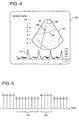
- the spectral Doppler display is provided to the scan converter where it is combined for display with the two dimensional image in a single display frame. Successive frames are displayed on the video display 18 and appear as shown in FIGURE 4.
- This figure shows a displayed frame 100 which includes the simultaneous display of a two dimensional image 102 and a spectral Doppler waveform 110.
- the wall filtered Doppler information signals are also provided to an audio display processing subsystem which begins with a 90° phase shifter 40.
- the phase shift imparted to the Doppler signals by this phase shifter enables the processing chain to distinguish between flow velocities in opposite directions.
- An audio gapfill processor 42 processes the received Doppler signals to fill the periods of time between the acquisition of Doppler information with synthesized signal information as described below.
- the continuous stream of received and gapfilled signals is applied to a direction processor 44 which converts the signals into signals representative of forward and reverse directions of flow.
- the processed signals, now in an audio spectrum are converted to an analog wave by a digital to analog converter 46.
- the analog wave is filtered by a low pass filter 48 to filter out high frequency artifacts and the filtered wave is amplified by an amplifier 52.
- the amplified audio wave is reproduced as a Doppler tone by a loudspeaker 50.
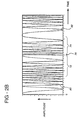
- FIGURE 2a shows at the left an audio wave 80 formed by a succession of digital signal samples which ends at the beginning of a gap 70 in time during which no new Doppler information is received while the ultrasound system acquires lines of image information.
- an audio wave 82 resumes with the commencement of reception of new Doppler information as the ultrasound system returns to Doppler scanning.
- the audio gapfill processor 42 stores the signal samples preceding and following the gap 70 and identifies the duration of the gap. Alternatively the processor 42 can be informed of the duration of the gap by a gapsize calculator which will be discussed below. Based upon the knowledge of the gap size the processor 42 begins filling the gap from each end of the gap with samples drawn from respective sides of the gap. In the case of the initial portion 72 of the gap, the processor 42 begins filling the gap from left to right (forward in time) with samples taken from the time of commencement of the gap and proceeding from right to left (backward in time). The last signal sample immediately preceding the gap portion 72 is used as the next sample in time, the first gapfilling sample. The signal sample which precedes the last signal sample before the gap is used as the second gapfilling sample, and so forth.
- the initial portion 72 of the gap in the audio wave is filled with a spectrum which is a continuation of the spectrum of the received signal 80 at the beginning of the gap 70 and in a reverse time sequence from the spectral progression leading up to the beginning of the gap.
- the same technique, but in a reverse time order, is used to fill the latter portion 74 of the gap 70.
- the first received sample after the gap 70 is used as the gapfilling sample adjacent to the end of the gap.
- the second received sample after the gap is used as the gapfilling sample preceding (in sequence and in time) the last gapfilling sample, and so forth.
- the latter portion 74 of the gap in the audio wave is filled with a spectrum which is a continuation of the spectrum of the received signal following the gap 70 and in a reverse time sequence from the spectral progression of the received signal which follows the gap.
- each portion of the gap is filled with gapfilling signals that smoothly progress spectrally from the signal spectrum at the beginning and ending points of the gap, as shown in FIGURE 2b.
- a spectral discontinuity is likely to exist in the middle of the gap 76 where the gapfilling samples proceeding from the two edges of the gap come together. While this discontinuity could be smoothed by averaging or interpolating the gapfilling samples as they approach each other at the gap center, it has been found sufficient to eliminate artifacts of this discontinuity by the cutoff of the low pass filter 48.
- FIGURES 3a and 3b show a portion of an exemplary spectral display which depicts the spread in flow velocities at a series of discrete points in time and their variation with time.
- the figures are premised upon a ramp input signal of changing velocity and would typically result from a few hundred sequential velocity estimations by the spectral estimation processor 34.
- a spectral display comprises two sections 90, 92 of received spectral information which have been interrupted by a gap in time 94 during which image scanning is performed by the ultrasound system.
- the spectral gapfill processor uses the received information 90, 92 before and after the gap 94 to develop gapfilling spectral lines proceeding toward the center of the gap from each end of the gap.
- the processor 36 begins by identifying the received spectral information existing at a time t 1 which precedes the beginning of the gap 94 by approximately one half of the duration of the gap.
- the spectral signal sample existing at time t 1 is displayed not once, but twice in succession.
- the spectral information sample next produced by the spectral estimation processor is reproduced twice for display. This doubling of the use of the received spectral estimates for display effectively stretches their use over a time which is twice that over which they were received, thus stretching the received samples over half of the gap 94 and in a manner which provides smooth spectral continuity.
- spectral samples can be repeated two, three, or more times so as to fill the initial portion of the gap.
- the initial repeated sample will be closer to the beginning of the gap than time t 1 in the preceding example.
- the latter portion 98 of the gap 94 is filled by similarly repeating spectral signal samples, but this time using samples of the section 92 received subsequent to the gap.
- the first valid spectral signal sample received after the gap at time t 2 is displayed as a gapfilling sample near the center 99 of the gap and is repeated.
- the second valid spectral signal sample follows and is repeated, and the succession of repeating samples continues until the sequence merges with the normally spaced real time sequence 92 and the repeating of samples is ended. Again, spectral continuity is provided over the latter portion 98 of the gap and extending forward in time through the end of the gap and into the valid sample sequence 92.
- FIGURE 4 shows the simultaneously produced two dimensional image 102.
- the image 102 shows the structure of a blood vessel 104, the directional line 106 along which Doppler information is acquired, and the sample volume 108 positioned in the blood vessel 104 which is the source of the signals used to produce the Doppler spectrum display 110.
- the inventive gapfilling technique makes possible the use of relative large gaps between intervals of Doppler signal acquisition without the onset of visual artifacts or audible distortion, it is possible to optimally proportion the interleaved image scanning and Doppler signal acquisition intervals for higher frame rates.
- a gapsize calculator 60 shown in FIGURE 1 receives as inputs the values of a number of user variable scan parameters and based upon the magnitudes and changes in these parameters adjusts the relative proportions of the image scan and Doppler acquisition intervals and their respective durations for optimally high frame rates.
- FIGURE 5 shows a number of vertical arrows, each representing the time of pulse transmission for either imaging or Doppler.
- the taller arrows represent Doppler pulse transmissions and the shorter arrows represent imaging pulse transmissions.
- the figure shows a first interval 120 during which a sequence of eight successive image lines are acquired, followed by a second interval 130 during which a sequence of four successive Doppler lines are acquired.
- the effect of the gapsize calculator 60 is to change the relative lengths of these two intervals and their durations in response to user change of the system scan parameters. These changes could range from a situation where every image line is succeeded by a series of Doppler lines, to a situation where a full frame of image lines is acquired between each interval of Doppler signal acquisition. The benefit obtained is optimization of the greatest attainable frame rate for a given set of scanning conditions.
- a number of scan parameters used by the gapsize calculator 60 to change the gapsize (the imaging interval 120) and the type of change they cause, are as follows. When the depth of a scan, such as the 6 cm. depth of the image in FIGURE 4, is increased, the gapsize calculator will respond by increasing the imaging interval 120.
- the gapsize When the frame rate of display is reduced the gapsize is correspondingly increased. As additional focal zones are added to an image the gapsize increases. As the image line density is increased the gapsize is increased. In response to a decrease in the width of the image sector the gapsize is decreased. When a zoom function is employed to enlarge a section of a full image, the gapsize is decreased. When the Doppler pulse transmission rate or PRF is decreased the gapsize is increased. A PRF change can be effected indirectly, for instance, by a change in the depth of the sample volume 108. A change in the performance of the wall filter 32, such as changing the filter characteristic to employ a steeper rolloff, will cause the gapsize to decrease.
- a change in the user setup or application may also result in a change in the gapsize.
- certain of these changes may be interactive and that limits in variation may be set as a matter of design choice. For instance, if the imaging depth is increased and it is attempted to increase the gapsize, a designed limitation on the gapsize increase could be encountered so as to prevent the onset of Doppler artifacts.
- the gapsize variation may be limited so as not to exceed the gapsize needed to acquire all of the lines for a full image. Such limitation may be employed in a particular embodiment as a matter of design choice.
Landscapes
- Health & Medical Sciences (AREA)
- Life Sciences & Earth Sciences (AREA)
- Physics & Mathematics (AREA)
- Engineering & Computer Science (AREA)
- Biomedical Technology (AREA)
- Heart & Thoracic Surgery (AREA)
- Veterinary Medicine (AREA)
- Remote Sensing (AREA)
- Public Health (AREA)
- Radar, Positioning & Navigation (AREA)
- Biophysics (AREA)
- Nuclear Medicine, Radiotherapy & Molecular Imaging (AREA)
- Pathology (AREA)
- Radiology & Medical Imaging (AREA)
- General Health & Medical Sciences (AREA)
- Animal Behavior & Ethology (AREA)
- Medical Informatics (AREA)
- Molecular Biology (AREA)
- Surgery (AREA)
- Acoustics & Sound (AREA)
- Computer Networks & Wireless Communication (AREA)
- Hematology (AREA)
- General Physics & Mathematics (AREA)
- Ultra Sonic Daignosis Equipment (AREA)
- Measurement Of Velocity Or Position Using Acoustic Or Ultrasonic Waves (AREA)
- Investigating Or Analyzing Materials By The Use Of Ultrasonic Waves (AREA)
- Image Processing (AREA)
- Image Analysis (AREA)
Claims (11)
- Système d'imagerie diagnostique par ultrasons qui affiche simultanément des informations d'image et Doppler dérivées d'intervalles alternés d'acquisition de signaux d'image ultrasonore et d'acquisition de signaux Doppler, comprenant un moyen pour développer des signaux à utiliser pour un affichage Doppler durant les interruptions dans la réception d'informations Doppler se produisant en raison de l'exécution par le système d'une acquisition de signaux d'image incluant :caractérisé en ce que :un moyen (34) réagissant à la réception de signaux d'informations Doppler pour produire des séquences de signaux d'estimation Doppler pendant des intervalles d'acquisition de signaux Doppler ;un moyen (36) réagissant auxdites séquences de signaux d'estimation Doppler pour produire des signaux de remplissage d'espaces vides à utiliser dans des interruptions entre lesdites séquences d'estimation Doppler comprenant un moyen réagissant aux signaux d'estimation Doppler (80) précédant une interruption (70) pour dériver une première séquence de signaux de remplissage d'espaces vides à appliquer sur une partie initiale (72) de ladite interruption, et un moyen réagissant aux signaux d'estimation Doppler (82) suivant ladite interruption (70) pour dériver une deuxième séquence de signaux de remplissage d'espaces vides à appliquer sur une partie finale (74) de ladite interruption ;un moyen réagissant auxdites séquences de signaux d'estimation Doppler et auxdites première et deuxième séquences intermédiaires de signaux de remplissage d'espaces vides pour afficher des informations Doppler ;ledit moyen pour dériver ladite première séquence de signaux de remplissage d'espaces vides comprend un moyen pour inverser l'ordre temporel de la séquence de signaux d'estimation Doppler précédant ladite interruption, de telle sorte que les signaux d'estimation Doppler en reculant dans le temps à partir du début de ladite interruption sont fournis en avançant dans le temps à partir dudit début de ladite interruption, etledit moyen pour dériver ladite deuxième séquence de signaux de remplissage d'espaces vides comprend un moyen pour inverser l'ordre temporel de la séquence de signaux d'estimation Doppler suivant ladite interruption, de telle sorte que les signaux d'estimation Doppler en avançant dans le temps à partir de la fin de ladite interruption sont fournis en reculant dans le temps à partir de ladite fin de ladite interruption.
- Système d'imagerie diagnostique par ultrasons suivant la revendication 1, dans lequel ledit moyen pour produire des signaux de remplissage d'espaces vides comprend un moyen pour dériver ladite première séquence de signaux de remplissage d'espaces vides qui sont continus sur le plan spectral avec le spectre desdits signaux d'estimation Doppler précédant ladite interruption, et un moyen pour dériver ladite deuxième séquence de signaux de remplissage d'espaces vides qui sont continus sur le plan spectral avec le spectre desdits signaux d'estimation Doppler suivant ladite interruption.
- Système d'imagerie diagnostique par ultrasons suivant l'une quelconque des revendications 1 et 2, dans lequel ledit moyen pour produire des signaux de remplissage d'espaces vides comprend en outre un moyen pour lisser le spectre entre lesdites première et deuxième séquences de signaux de remplissage d'espaces vides.
- Système d'imagerie diagnostique par ultrasons suivant l'une quelconque des revendications 1 à 3, dans lequel ledit moyen pour afficher des informations Doppler comprend un système audio (42).
- Système d'imagerie diagnostique par ultrasons suivant la revendication 1, dans lequel ledit moyen pour dériver une première séquence de signaux de remplissage d'espaces vides comprend un moyen pour développer une séquence de signaux de remplissage d'espaces vides en avançant dans le temps à partir d'un signal d'estimation Doppler qui précède le début de ladite interruption en répétant chaque signal d'estimation Doppler successivement jusqu'au signal d'estimation Doppler précédant immédiatement ladite interruption.
- Système d'imagerie diagnostique par ultrasons suivant la revendication 5, dans lequel ledit moyen pour dériver une deuxième séquence de signaux de remplissage d'espaces vides comprend un moyen pour développer une séquence de signaux de remplissage d'espaces vides en avançant dans le temps à partir du centre de ladite interruption qui est dérivée en répétant des signaux d'estimation Doppler en avançant dans le temps à partir de ladite fin de ladite interruption.
- Système d'imagerie diagnostique par ultrasons suivant la revendication 6, dans lequel ledit moyen pour produire des signaux de remplissage d'espaces vides comprend en outre un moyen pour lisser le spectre entre lesdites première et deuxième séquences de signaux de remplissage d'espaces vides.
- Système d'imagerie diagnostique par ultrasons suivant la revendication 8, dans lequel ledit moyen pour afficher des informations Doppler comprend un système d'affichage spectral Doppler.
- Système d'imagerie diagnostique par ultrasons suivant l'une quelconque des revendications 1 à 8, qui affiche simultanément une image ultrasonore et un affichage continu d'informations Doppler spectrales dérivées d'intervalles de balayage alternés d'acquisition de signaux d'image ultrasonore et d'acquisition de signaux Doppler, comprenant :un moyen Doppler réagissant à la réception de signaux d'informations Doppler pour produire des signaux d'estimation Doppler pendant des intervalles d'acquisition de signaux Doppler ;un moyen d'imagerie réagissant à la réception de signaux d'informations d'image pour produire des lignes d'image ultrasonore pendant des intervalles d'acquisition de signaux d'image ultrasonore ;un moyen, couplé audit moyen Doppler et audit moyen d'imagerie, et réagissant au réglage par l'utilisateur de paramètres de commande de balayage, pour varier les durées desdits intervalles d'acquisition de signaux Doppler et d'acquisition de signaux d'image ultrasonore, etun moyen, couplé audit moyen Doppler et audit moyen d'imagerie, pour afficher simultanément des informations Doppler avec une image ultrasonore.
- Système d'imagerie diagnostique par ultrasons suivant la revendication 9, dans lequel lesdits paramètres de commande de balayage comprennent un ou plusieurs des paramètres de profondeur de balayage, de durée d'image, de nombre de zones focales, de densité de ligne d'image, de largeur d'image, de zoom d'image, de cadence de transmission d'impulsions Doppler, de profondeur de volume d'échantillonnage et de caractéristique de filtrage de paroi.
- Système d'imagerie diagnostique par ultrasons suivant l'une quelconque des revendications 9 à 10, comprenant :ledit dispositif de remplissage d'espaces vides d'affichage Doppler comprenant un moyen réagissant aux signaux d'estimation Doppler précédant une interruption pour dériver une première séquence de signaux de remplissage d'espaces vides sur une partie initiale de ladite interruption, et un moyen réagissant aux signaux d'estimation Doppler suivant ladite interruption pour dériver une deuxième séquence de signaux de remplissage d'espaces vides sur une partie finale de ladite interruption.un dispositif de remplissage d'espaces vides d'affichage Doppler réagissant audit moyen Doppler pour remplir des interruptions dans lesdits signaux d'estimation Doppler se produisant pendant lesdits intervalles d'acquisition de signaux d'image ultrasonore afin de fournir une séquence pratiquement continue de signaux d'informations Doppler spectrales ;un moyen couplé audit dispositif de remplissage d'espaces vides d'affichage Doppler et audit moyen d'imagerie pour afficher simultanément un affichage continu d'informations Doppler spectrales et une image ultrasonore ;
Applications Claiming Priority (2)
| Application Number | Priority Date | Filing Date | Title |
|---|---|---|---|
| US322802 | 1989-03-13 | ||
| US08/322,802 US5476097A (en) | 1994-10-13 | 1994-10-13 | Simultaneous ultrasonic imaging and Doppler display system |
Publications (3)
| Publication Number | Publication Date |
|---|---|
| EP0706777A2 EP0706777A2 (fr) | 1996-04-17 |
| EP0706777A3 EP0706777A3 (fr) | 1998-04-29 |
| EP0706777B1 true EP0706777B1 (fr) | 2002-08-07 |
Family
ID=23256483
Family Applications (1)
| Application Number | Title | Priority Date | Filing Date |
|---|---|---|---|
| EP95307243A Expired - Lifetime EP0706777B1 (fr) | 1994-10-13 | 1995-10-12 | Système simultané d'imagerie ultrasonore et d'affichage doppler |
Country Status (5)
| Country | Link |
|---|---|
| US (1) | US5476097A (fr) |
| EP (1) | EP0706777B1 (fr) |
| JP (1) | JPH08229035A (fr) |
| AT (1) | ATE221752T1 (fr) |
| DE (1) | DE69527685T2 (fr) |
Families Citing this family (41)
| Publication number | Priority date | Publication date | Assignee | Title |
|---|---|---|---|---|
| US5642732A (en) * | 1995-05-03 | 1997-07-01 | Acuson Corporation | Apparatus and method for estimating missing doppler signals and spectra |
| US6059727A (en) * | 1995-06-15 | 2000-05-09 | The Regents Of The University Of Michigan | Method and apparatus for composition and display of three-dimensional image from two-dimensional ultrasound scan data |
| US5724974A (en) * | 1996-03-22 | 1998-03-10 | Acuson Corporation | Two-dimensional ultrasound display system |
| US5720291A (en) * | 1996-03-22 | 1998-02-24 | Advanced Technology Laboratories, Inc. | Three dimensional medical ultrasonic diagnostic image of tissue texture and vasculature |
| JP3657706B2 (ja) * | 1996-09-11 | 2005-06-08 | 株式会社日立メディコ | 超音波ドプラ診断装置 |
| US5865749A (en) * | 1996-11-07 | 1999-02-02 | Data Sciences International, Inc. | Blood flow meter apparatus and method of use |
| US6626838B2 (en) | 1996-11-07 | 2003-09-30 | Transoma Medical, Inc. | Blood flow meter apparatus and method of use |
| US6074347A (en) * | 1996-12-04 | 2000-06-13 | Acuson Corporation | Method and apparatus for controlling acoustic signal bandwidth in an ultrasonic diagnostic imaging system |
| US5919137A (en) * | 1996-12-04 | 1999-07-06 | Acuson Corporation | Ultrasonic diagnostic imaging system with programmable acoustic signal processor |
| US5961460A (en) * | 1997-04-11 | 1999-10-05 | Acuson Corporation | Ultrasound imaging enhancement methods and systems |
| US6030345A (en) * | 1997-05-22 | 2000-02-29 | Acuson Corporation | Method and system for ultrasound enhanced-resolution spectral Doppler |
| US6196972B1 (en) * | 1998-11-11 | 2001-03-06 | Spentech, Inc. | Doppler ultrasound method and apparatus for monitoring blood flow |
| US6524249B2 (en) | 1998-11-11 | 2003-02-25 | Spentech, Inc. | Doppler ultrasound method and apparatus for monitoring blood flow and detecting emboli |
| US6547736B1 (en) | 1998-11-11 | 2003-04-15 | Spentech, Inc. | Doppler ultrasound method and apparatus for monitoring blood flow and detecting emboli |
| US6110113A (en) * | 1998-12-15 | 2000-08-29 | Siemens Medical Systems, Inc. | Method and apparatus for removing transients and gaps from ultrasound echo signals |
| US6364838B1 (en) * | 2000-01-11 | 2002-04-02 | Siemens Medical Soulutions, Usa, Inc. | Pulsed wave doppler processing using aliased spectral data |
| AUPS335502A0 (en) | 2002-07-03 | 2002-07-25 | Uscom Pty Ltd | Pacemaker evaluation method and apparatus |
| AU2003281829B2 (en) * | 2002-08-06 | 2009-07-16 | Uscom Limited | Blood flow analysis system |
| AU2002950611A0 (en) * | 2002-08-06 | 2002-09-12 | Uscom Pty Ltd | Blood flow analysis system |
| AU2003900261A0 (en) | 2003-01-22 | 2003-02-06 | Uscom Pty Ltd | Method and system for the determination of blood characteristics |
| US7128713B2 (en) * | 2003-07-10 | 2006-10-31 | Spentech, Inc. | Doppler ultrasound method and apparatus for monitoring blood flow and hemodynamics |
| US7578792B2 (en) * | 2003-07-21 | 2009-08-25 | Siemens Medical Solutions Usa, Inc. | Automatic optimization in spectral Doppler ultrasound imaging |
| WO2005015907A1 (fr) * | 2003-08-08 | 2005-02-17 | Matsushita Electric Industrial Co., Ltd. | Dispositif et procede de traitement de donnees |
| JP4583118B2 (ja) * | 2004-09-10 | 2010-11-17 | 株式会社東芝 | 超音波診断装置および超音波診断装置の制御方法 |
| JP4653454B2 (ja) * | 2004-10-22 | 2011-03-16 | 株式会社東芝 | 超音波診断装置、及びこの装置の制御プログラム |
| US7771358B2 (en) * | 2005-05-20 | 2010-08-10 | Spentech, Inc. | System and method for grading microemboli monitored by a multi-gate doppler ultrasound system |
| US8162837B2 (en) * | 2005-06-13 | 2012-04-24 | Spentech, Inc. | Medical doppler ultrasound system for locating and tracking blood flow |
| CN100544677C (zh) * | 2005-08-16 | 2009-09-30 | 深圳迈瑞生物医疗电子股份有限公司 | 处理多普勒信号间隙的方法 |
| JP4907382B2 (ja) * | 2007-02-23 | 2012-03-28 | ジーイー・メディカル・システムズ・グローバル・テクノロジー・カンパニー・エルエルシー | 超音波画像表示方法および超音波診断装置 |
| KR100961854B1 (ko) * | 2007-03-16 | 2010-06-09 | 주식회사 메디슨 | 도플러 스펙트럼 영상을 디스플레이하기 위한 초음파 진단시스템 및 방법 |
| CN101336830B (zh) * | 2007-07-03 | 2012-07-04 | 深圳迈瑞生物医疗电子股份有限公司 | 用于超声诊断成像的正交多普勒信号间隙填充方法与装置 |
| JP2009112356A (ja) * | 2007-11-02 | 2009-05-28 | Ge Medical Systems Global Technology Co Llc | 超音波診断装置 |
| CN101461719B (zh) * | 2007-12-18 | 2012-02-01 | 深圳迈瑞生物医疗电子股份有限公司 | 一种多普勒扫描变换实现方法和装置 |
| CN102370499B (zh) | 2010-08-26 | 2014-05-07 | 深圳迈瑞生物医疗电子股份有限公司 | 多普勒图像、b型图像和彩色血流图像同时显示的方法和系统 |
| JP5838383B2 (ja) * | 2012-06-29 | 2016-01-06 | ジーイー・メディカル・システムズ・グローバル・テクノロジー・カンパニー・エルエルシー | 超音波診断装置及びその制御プログラム |
| US9011338B2 (en) | 2012-07-12 | 2015-04-21 | Siemens Medical Solutions Usa, Inc. | Gap filling for spectral doppler ultrasound |
| JP6202841B2 (ja) * | 2013-03-18 | 2017-09-27 | 東芝メディカルシステムズ株式会社 | 超音波診断装置 |
| EP2989992B1 (fr) * | 2014-09-01 | 2022-11-16 | Samsung Medison Co., Ltd. | Appareil d'imagerie médicale et procédé de génération d'images médicales |
| JP6733445B2 (ja) * | 2016-09-13 | 2020-07-29 | コニカミノルタ株式会社 | 超音波診断装置、超音波画像生成方法及びプログラム |
| US11779311B2 (en) | 2018-09-14 | 2023-10-10 | Fujifilm Sonosite, Inc. | Method and apparatus for performing spectral doppler imaging |
| US11109841B2 (en) * | 2018-12-06 | 2021-09-07 | General Electric Company | Method and system for simultaneously presenting doppler signals of a multi-gated doppler signal corresponding with different anatomical structures |
Family Cites Families (12)
| Publication number | Priority date | Publication date | Assignee | Title |
|---|---|---|---|---|
| NO150015C (no) * | 1981-11-13 | 1984-08-08 | Vingmed As | Fremgangsmaate ved blodstroemhastighetsmaaling med ultralyd, kombinert med ekko-amplitudeavbildning, for undersoekelse av levende biologiske strukturer |
| NO831718L (no) * | 1983-05-13 | 1984-11-14 | Vingmed As | Fremgangsmaate og apparat ved blodstroem-hastighetsmaaling med ultralyd for dannelse av todimensjonal avbildning av blodets hastighet |
| NO831719L (no) * | 1983-05-13 | 1984-11-14 | Vingmed As | Fremgangsmaate og anordning for syntetisering av et kontinuerlig estimatsignal ut fra bruddstykker av et gaussisk signal fremkommet ved ultralyd-dopplermaaling paa en fluidumstroem |
| DE3374109D1 (en) * | 1983-10-28 | 1987-11-19 | Ibm | Method of recovering lost information in a digital speech transmission system, and transmission system using said method |
| JPS6125534A (ja) * | 1984-07-16 | 1986-02-04 | 横河メディカルシステム株式会社 | 画像診断装置 |
| JP2763126B2 (ja) * | 1989-02-10 | 1998-06-11 | 株式会社東芝 | カラー超音波診断装置 |
| JPH062134B2 (ja) * | 1989-09-08 | 1994-01-12 | 株式会社東芝 | 超音波診断装置 |
| US5016641A (en) * | 1989-11-13 | 1991-05-21 | Advanced Technology Laboratories, Inc. | Spectral interpolation of ultrasound Doppler signal |
| US5188113A (en) * | 1990-04-04 | 1993-02-23 | Kabushiki Kaisha Toshiba | Ultrasonic diagnosis apparatus |
| CA2048960C (fr) * | 1990-08-20 | 1995-08-01 | Hisashi Hagiwara | Debitmetre sanguin a effet doppler ultrasonore |
| JP3144819B2 (ja) * | 1991-04-17 | 2001-03-12 | 株式会社東芝 | 超音波診断装置 |
| US5555514A (en) * | 1992-07-20 | 1996-09-10 | Ge Yokogawa Medical Systems, Limited | Method of and apparatus for generating doppler sounds |
-
1994
- 1994-10-13 US US08/322,802 patent/US5476097A/en not_active Expired - Lifetime
-
1995
- 1995-10-11 JP JP7288140A patent/JPH08229035A/ja active Pending
- 1995-10-12 AT AT95307243T patent/ATE221752T1/de not_active IP Right Cessation
- 1995-10-12 EP EP95307243A patent/EP0706777B1/fr not_active Expired - Lifetime
- 1995-10-12 DE DE69527685T patent/DE69527685T2/de not_active Expired - Fee Related
Also Published As
| Publication number | Publication date |
|---|---|
| DE69527685T2 (de) | 2003-04-03 |
| US5476097A (en) | 1995-12-19 |
| DE69527685D1 (de) | 2002-09-12 |
| EP0706777A3 (fr) | 1998-04-29 |
| ATE221752T1 (de) | 2002-08-15 |
| EP0706777A2 (fr) | 1996-04-17 |
| JPH08229035A (ja) | 1996-09-10 |
Similar Documents
| Publication | Publication Date | Title |
|---|---|---|
| EP0706777B1 (fr) | Système simultané d'imagerie ultrasonore et d'affichage doppler | |
| US6139501A (en) | Coincident tissue and motion ultrasonic diagnostic imaging | |
| US5961462A (en) | Ultrasonic doppler imaging at high frame rates of display | |
| US5379642A (en) | Method and apparatus for performing imaging | |
| US5301674A (en) | Method and apparatus for focusing transmission and reception of ultrasonic beams | |
| EP1664840B1 (fr) | Combinaison spatiale ultrasonore avec transmission simultanee de plusieurs faisceaux | |
| US6228031B1 (en) | High frame rate ultrasonic diagnostic imaging systems with motion artifact reduction | |
| US5797846A (en) | Method to control frame rate in ultrasound imaging | |
| US5908391A (en) | Method and apparatus for enhancing resolution and sensitivity in color flow ultrasound imaging using multiple transmit focal zones | |
| JP3144819B2 (ja) | 超音波診断装置 | |
| US5016641A (en) | Spectral interpolation of ultrasound Doppler signal | |
| US5438994A (en) | Ultrasonic diagnostic image scanning | |
| JP2010511420A (ja) | マルチラインカラーフロー及び血管超音波イメージングに関する方法及び装置 | |
| US5144954A (en) | Ultrasonic diagnosing apparatus | |
| EP1697765B1 (fr) | Imagerie de contraste diagnostique a ultrasons, a combinaison spatiale | |
| JPH078492A (ja) | 超音波診断装置 | |
| KR20080060625A (ko) | 대상체의 움직임에 기초하여 초음파 영상 획득하는 초음파진단 시스템 및 방법 | |
| US5827189A (en) | Method and apparatus for preventing axial spatial aliasing in ultrasound imager having complex signal detector | |
| JP2021529039A (ja) | カラードップラー超音波イメージングを行うための方法及びシステム | |
| CN112826529B (zh) | 一种基于直角梯形的超声空间复合方法及装置 | |
| JP2772049B2 (ja) | 超音波診断装置 | |
| Kirkhorn et al. | A new technique for improved spatial resolution in high frame rate color Doppler imaging | |
| JP2597584B2 (ja) | 超音波診断装置 | |
| JPH03297454A (ja) | 超音波診断装置 | |
| JP3437642B2 (ja) | 超音波診断装置 |
Legal Events
| Date | Code | Title | Description |
|---|---|---|---|
| PUAI | Public reference made under article 153(3) epc to a published international application that has entered the european phase |
Free format text: ORIGINAL CODE: 0009012 |
|
| AK | Designated contracting states |
Kind code of ref document: A2 Designated state(s): AT BE CH DE DK ES FR GB GR IE IT LI LU MC NL PT SE |
|
| PUAL | Search report despatched |
Free format text: ORIGINAL CODE: 0009013 |
|
| AK | Designated contracting states |
Kind code of ref document: A3 Designated state(s): AT BE CH DE DK ES FR GB GR IE IT LI LU MC NL PT SE |
|
| 17P | Request for examination filed |
Effective date: 19981002 |
|
| 17Q | First examination report despatched |
Effective date: 19990823 |
|
| GRAG | Despatch of communication of intention to grant |
Free format text: ORIGINAL CODE: EPIDOS AGRA |
|
| GRAG | Despatch of communication of intention to grant |
Free format text: ORIGINAL CODE: EPIDOS AGRA |
|
| GRAH | Despatch of communication of intention to grant a patent |
Free format text: ORIGINAL CODE: EPIDOS IGRA |
|
| GRAH | Despatch of communication of intention to grant a patent |
Free format text: ORIGINAL CODE: EPIDOS IGRA |
|
| GRAA | (expected) grant |
Free format text: ORIGINAL CODE: 0009210 |
|
| AK | Designated contracting states |
Kind code of ref document: B1 Designated state(s): AT BE CH DE DK ES FR GB GR IE IT LI LU MC NL PT SE |
|
| PG25 | Lapsed in a contracting state [announced via postgrant information from national office to epo] |
Ref country code: NL Free format text: LAPSE BECAUSE OF FAILURE TO SUBMIT A TRANSLATION OF THE DESCRIPTION OR TO PAY THE FEE WITHIN THE PRESCRIBED TIME-LIMIT Effective date: 20020807 Ref country code: LI Free format text: LAPSE BECAUSE OF FAILURE TO SUBMIT A TRANSLATION OF THE DESCRIPTION OR TO PAY THE FEE WITHIN THE PRESCRIBED TIME-LIMIT Effective date: 20020807 Ref country code: IT Free format text: LAPSE BECAUSE OF FAILURE TO SUBMIT A TRANSLATION OF THE DESCRIPTION OR TO PAY THE FEE WITHIN THE PRESCRIBED TIME-LIMIT;WARNING: LAPSES OF ITALIAN PATENTS WITH EFFECTIVE DATE BEFORE 2007 MAY HAVE OCCURRED AT ANY TIME BEFORE 2007. THE CORRECT EFFECTIVE DATE MAY BE DIFFERENT FROM THE ONE RECORDED. Effective date: 20020807 Ref country code: GR Free format text: LAPSE BECAUSE OF FAILURE TO SUBMIT A TRANSLATION OF THE DESCRIPTION OR TO PAY THE FEE WITHIN THE PRESCRIBED TIME-LIMIT Effective date: 20020807 Ref country code: FR Free format text: LAPSE BECAUSE OF FAILURE TO SUBMIT A TRANSLATION OF THE DESCRIPTION OR TO PAY THE FEE WITHIN THE PRESCRIBED TIME-LIMIT Effective date: 20020807 Ref country code: CH Free format text: LAPSE BECAUSE OF FAILURE TO SUBMIT A TRANSLATION OF THE DESCRIPTION OR TO PAY THE FEE WITHIN THE PRESCRIBED TIME-LIMIT Effective date: 20020807 Ref country code: BE Free format text: LAPSE BECAUSE OF FAILURE TO SUBMIT A TRANSLATION OF THE DESCRIPTION OR TO PAY THE FEE WITHIN THE PRESCRIBED TIME-LIMIT Effective date: 20020807 Ref country code: AT Free format text: LAPSE BECAUSE OF FAILURE TO SUBMIT A TRANSLATION OF THE DESCRIPTION OR TO PAY THE FEE WITHIN THE PRESCRIBED TIME-LIMIT Effective date: 20020807 |
|
| REF | Corresponds to: |
Ref document number: 221752 Country of ref document: AT Date of ref document: 20020815 Kind code of ref document: T |
|
| REG | Reference to a national code |
Ref country code: GB Ref legal event code: FG4D |
|
| REG | Reference to a national code |
Ref country code: CH Ref legal event code: EP |
|
| REG | Reference to a national code |
Ref country code: IE Ref legal event code: FG4D |
|
| REF | Corresponds to: |
Ref document number: 69527685 Country of ref document: DE Date of ref document: 20020912 |
|
| REG | Reference to a national code |
Ref country code: GB Ref legal event code: 746 Effective date: 20020911 |
|
| PG25 | Lapsed in a contracting state [announced via postgrant information from national office to epo] |
Ref country code: LU Free format text: LAPSE BECAUSE OF NON-PAYMENT OF DUE FEES Effective date: 20021012 |
|
| PG25 | Lapsed in a contracting state [announced via postgrant information from national office to epo] |
Ref country code: IE Free format text: LAPSE BECAUSE OF NON-PAYMENT OF DUE FEES Effective date: 20021014 |
|
| PG25 | Lapsed in a contracting state [announced via postgrant information from national office to epo] |
Ref country code: SE Free format text: LAPSE BECAUSE OF FAILURE TO SUBMIT A TRANSLATION OF THE DESCRIPTION OR TO PAY THE FEE WITHIN THE PRESCRIBED TIME-LIMIT Effective date: 20021107 Ref country code: DK Free format text: LAPSE BECAUSE OF FAILURE TO SUBMIT A TRANSLATION OF THE DESCRIPTION OR TO PAY THE FEE WITHIN THE PRESCRIBED TIME-LIMIT Effective date: 20021107 |
|
| PG25 | Lapsed in a contracting state [announced via postgrant information from national office to epo] |
Ref country code: PT Free format text: LAPSE BECAUSE OF FAILURE TO SUBMIT A TRANSLATION OF THE DESCRIPTION OR TO PAY THE FEE WITHIN THE PRESCRIBED TIME-LIMIT Effective date: 20021122 |
|
| NLV1 | Nl: lapsed or annulled due to failure to fulfill the requirements of art. 29p and 29m of the patents act | ||
| REG | Reference to a national code |
Ref country code: CH Ref legal event code: PL |
|
| PG25 | Lapsed in a contracting state [announced via postgrant information from national office to epo] |
Ref country code: ES Free format text: LAPSE BECAUSE OF FAILURE TO SUBMIT A TRANSLATION OF THE DESCRIPTION OR TO PAY THE FEE WITHIN THE PRESCRIBED TIME-LIMIT Effective date: 20030228 |
|
| PG25 | Lapsed in a contracting state [announced via postgrant information from national office to epo] |
Ref country code: MC Free format text: LAPSE BECAUSE OF NON-PAYMENT OF DUE FEES Effective date: 20030501 |
|
| PLBE | No opposition filed within time limit |
Free format text: ORIGINAL CODE: 0009261 |
|
| STAA | Information on the status of an ep patent application or granted ep patent |
Free format text: STATUS: NO OPPOSITION FILED WITHIN TIME LIMIT |
|
| 26N | No opposition filed |
Effective date: 20030508 |
|
| REG | Reference to a national code |
Ref country code: IE Ref legal event code: MM4A |
|
| PGFP | Annual fee paid to national office [announced via postgrant information from national office to epo] |
Ref country code: DE Payment date: 20031215 Year of fee payment: 9 |
|
| PGFP | Annual fee paid to national office [announced via postgrant information from national office to epo] |
Ref country code: GB Payment date: 20041028 Year of fee payment: 10 |
|
| PG25 | Lapsed in a contracting state [announced via postgrant information from national office to epo] |
Ref country code: DE Free format text: LAPSE BECAUSE OF NON-PAYMENT OF DUE FEES Effective date: 20050503 |
|
| PG25 | Lapsed in a contracting state [announced via postgrant information from national office to epo] |
Ref country code: GB Free format text: LAPSE BECAUSE OF NON-PAYMENT OF DUE FEES Effective date: 20051012 |
|
| GBPC | Gb: european patent ceased through non-payment of renewal fee |
Effective date: 20051012 |