EP0706603B1 - Seilzug-fensterheber - Google Patents
Seilzug-fensterheber Download PDFInfo
- Publication number
- EP0706603B1 EP0706603B1 EP94919674A EP94919674A EP0706603B1 EP 0706603 B1 EP0706603 B1 EP 0706603B1 EP 94919674 A EP94919674 A EP 94919674A EP 94919674 A EP94919674 A EP 94919674A EP 0706603 B1 EP0706603 B1 EP 0706603B1
- Authority
- EP
- European Patent Office
- Prior art keywords
- cable
- window lifter
- window
- pull
- lifter according
- Prior art date
- Legal status (The legal status is an assumption and is not a legal conclusion. Google has not performed a legal analysis and makes no representation as to the accuracy of the status listed.)
- Expired - Lifetime
Links
Images
Classifications
-
- F—MECHANICAL ENGINEERING; LIGHTING; HEATING; WEAPONS; BLASTING
- F16—ENGINEERING ELEMENTS AND UNITS; GENERAL MEASURES FOR PRODUCING AND MAINTAINING EFFECTIVE FUNCTIONING OF MACHINES OR INSTALLATIONS; THERMAL INSULATION IN GENERAL
- F16C—SHAFTS; FLEXIBLE SHAFTS; ELEMENTS OR CRANKSHAFT MECHANISMS; ROTARY BODIES OTHER THAN GEARING ELEMENTS; BEARINGS
- F16C1/00—Flexible shafts; Mechanical means for transmitting movement in a flexible sheathing
- F16C1/26—Construction of guiding-sheathings or guiding-tubes
- F16C1/262—End fittings; Attachment thereof to the sheathing or tube
-
- E—FIXED CONSTRUCTIONS
- E05—LOCKS; KEYS; WINDOW OR DOOR FITTINGS; SAFES
- E05F—DEVICES FOR MOVING WINGS INTO OPEN OR CLOSED POSITION; CHECKS FOR WINGS; WING FITTINGS NOT OTHERWISE PROVIDED FOR, CONCERNED WITH THE FUNCTIONING OF THE WING
- E05F11/00—Man-operated mechanisms for operating wings, including those which also operate the fastening
- E05F11/38—Man-operated mechanisms for operating wings, including those which also operate the fastening for sliding windows, e.g. vehicle windows, to be opened or closed by vertical movement
- E05F11/48—Man-operated mechanisms for operating wings, including those which also operate the fastening for sliding windows, e.g. vehicle windows, to be opened or closed by vertical movement operated by cords or chains or other flexible elongated pulling elements, e.g. tapes
- E05F11/481—Man-operated mechanisms for operating wings, including those which also operate the fastening for sliding windows, e.g. vehicle windows, to be opened or closed by vertical movement operated by cords or chains or other flexible elongated pulling elements, e.g. tapes for vehicle windows
- E05F11/483—Man-operated mechanisms for operating wings, including those which also operate the fastening for sliding windows, e.g. vehicle windows, to be opened or closed by vertical movement operated by cords or chains or other flexible elongated pulling elements, e.g. tapes for vehicle windows by cables
- E05F11/488—Man-operated mechanisms for operating wings, including those which also operate the fastening for sliding windows, e.g. vehicle windows, to be opened or closed by vertical movement operated by cords or chains or other flexible elongated pulling elements, e.g. tapes for vehicle windows by cables with two cable connections to the window glass
-
- E—FIXED CONSTRUCTIONS
- E05—LOCKS; KEYS; WINDOW OR DOOR FITTINGS; SAFES
- E05Y—INDEXING SCHEME RELATING TO HINGES OR OTHER SUSPENSION DEVICES FOR DOORS, WINDOWS OR WINGS AND DEVICES FOR MOVING WINGS INTO OPEN OR CLOSED POSITION, CHECKS FOR WINGS AND WING FITTINGS NOT OTHERWISE PROVIDED FOR, CONCERNED WITH THE FUNCTIONING OF THE WING
- E05Y2600/00—Mounting or coupling arrangements for elements provided for in this subclass
- E05Y2600/50—Mounting methods; Positioning
- E05Y2600/52—Toolless
- E05Y2600/53—Snapping
-
- E—FIXED CONSTRUCTIONS
- E05—LOCKS; KEYS; WINDOW OR DOOR FITTINGS; SAFES
- E05Y—INDEXING SCHEME RELATING TO HINGES OR OTHER SUSPENSION DEVICES FOR DOORS, WINDOWS OR WINGS AND DEVICES FOR MOVING WINGS INTO OPEN OR CLOSED POSITION, CHECKS FOR WINGS AND WING FITTINGS NOT OTHERWISE PROVIDED FOR, CONCERNED WITH THE FUNCTIONING OF THE WING
- E05Y2900/00—Application of doors, windows, wings or fittings thereof
- E05Y2900/50—Application of doors, windows, wings or fittings thereof for vehicles
- E05Y2900/53—Application of doors, windows, wings or fittings thereof for vehicles characterised by the type of wing
- E05Y2900/55—Windows
Definitions
- the invention relates to a cable window regulator according to the preamble of claim 1.
- Such a cable window regulator is already known from FR-PS 11 99 784.
- This window lifter has a drive unit for the cable of the cable, which is guided over a vertical distance by means of deflection parts and is connected in this section to a driver which holds the window pane.
- the driver has no separate guide and is fixed to the cable by means of a clamping piece.
- the type of connection between the driver and the cable is structurally complex in this known embodiment, with the additional risk of the connection between the cable and the driver being unintentionally released.
- Another cable window regulator is known from US-A-4 920 697.
- a cross member is provided, which is connected to the window pane, which is connected at both ends to drivers, which in turn are attached to the cable.
- DE 40 15 774 A1 apparently discloses a window adjusting device with a holder which can be moved up and down by means of a cable and which is connected to the window pane.
- the holder is not only connected to the cable, but is also guided in a guide rail by means of a guide roller.
- a connecting piece is provided with a receiving recess into which a clamping piece attached to the cable can be inserted.
- the connecting piece is fastened to the holder in that a pin provided on the connecting piece is inserted and secured through a hole in the holder.
- a cable window regulator for motor vehicles which has a drive unit with two outlets for the cable, which is laid endlessly in two intersecting loops.
- the rope is guided over four deflection pulleys or bends, which are mounted on the corner areas of two spaced-apart guide rails.
- Driver plates for the window pane are slidably guided on the guide rails, on which the cable pull moving the window pane acts.
- the pane itself is guided with its front edges in further guides of the door, as is known, for example, from DE 39 21 289 C1.
- the disadvantage here is the design effort and, above all, the over-determination of the pane guide as a whole, since the guides of the window lifter or the driver and the pane guides must be exactly matched to one another.
- the invention has for its object to develop a cable window regulator of the type mentioned in such a way that simple assembly and safe and permanent fixing of the cable is guaranteed on the driver.
- a particularly simple connection of the cable to the driver is achieved in that the driver can be inserted into a recess in the plate-shaped base element, the driver being fixed to the cable without tools.
- the clamping piece has a chamber for receiving a holding element firmly connected to the cable pull and openings for the cable formed on the end faces of the chamber, a simple and secure fixing between the Cable and the basic element possible.
- the cable between the basic element of the driver is fixed in that the cable, with its holding element, for example in the form of a nipple, is passed through the recess in the basic element in the manner of a loop, then the holding element is inserted into the chamber of the clamping piece and then the Clamping piece is pressed into the recess on the base element.
- the rope is immovably connected to the driver, thus creating the connection between the cable and the driver.
- This special type of fixing the cable to the holding element by means of the clamping piece also has the effect that unintentional loosening of the cable from the driver is reliably avoided.
- the clamping piece can be inserted into the recess from the top of the basic element, while the cable is guided to the side of the chamber of the clamping piece along the underside of the basic element, an unintentional escape of the cable from the chamber of the clamping piece is not possible. Furthermore, due to the special guidance on the base element, the cable pull itself acts as a safeguard against the accidental escape of the clamping piece from the recess in the base element.
- the cable is guided endlessly by the at least one driver. In this way, a simple adjustment possibility is achieved between the window pane and the driver to be fixed on the rope.
- the deflecting parts for the rope on the guide rails for the window pane are arranged, the design effort of the window lifter is significantly reduced. Overall, by eliminating the rails for guiding the driver or drivers connected to the window pane, overdetermination of the guide system is avoided and a more favorable torque of the drive reached. Another advantage is that the noise problems caused by the known window regulators due to stick-slip phenomena are no longer present.
- the measure that the clamping piece has latching lugs, which engage behind the base element in the region of the recess in a clamping manner, has proven to be particularly advantageous, as a result of which the assembly of the cable on the driver is further improved.
- the clamping piece for the purpose of assembly can be easily pressed into the recess of the basic element from the top of the basic element, the side of the chamber of the clamping piece emerging rope sections are guided through the slots to the bottom of the base element. Damage to the cable during assembly is thereby avoided safely and in a structurally simple manner.
- an adjustment device for the cable length of the cable is provided with a spacer that can be inserted in a separation point of the outer hose of the cable.
- the rope can initially have a certain amount of slack in order to be looped over the deflecting parts in a simple manner.
- the lots are removed after assembly by means of a spacer, which is inserted in the separation point of the cable.
- the adjusting device has a base body with a through hole for the cable pull and a longitudinal slot for inserting the spacer between the front ends of the outer tube formed by the separation point of the cable.
- the handling can be further improved in that the bore of the base body, preferably in the area of the longitudinal slot, has a stop for the outer tube of the cable, so that it is easier to pull the outer tube out of the area of the longitudinal slot.
- the fixing of the spacer on the base body can be realized in a particularly simple manner in that the spacer is held in the clamp seat, for example by means of locking and counter-locking means on the base body, so that the spacer can be inserted without tools.
- the spacer encompasses the base body with circular segment-shaped wall extensions and is preferably secured against axial displacement between two contact shoulders formed on the base body. In this way, undesired detachment of the spacer from the base body is avoided in any case.
- the spacer has a web-shaped extension with a longitudinal groove for receiving the cable, the end faces of the extension forming a stop for the ends of the protective hose of the cable in the region of the separation point.
- the base body and / or the spacer of the adjusting device and / or the clamping piece consist of plastic.
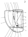
- the vehicle door as shown in Figure 1, has a lower door box 1 and an upper window frame 2.
- the door box 1 is closed on the outside by an outer door skin 3, while it is usually covered on the inside with a door inner lining.
- the door interior trim is removed, so that the window lifter arranged in the door box 1 is visible.
- the window frame 2 has an upper frame part 4, a rear frame part 5 and a front frame part 6.
- the door shown is usually pivotally attached to its front side 7 with a support column of a vehicle via hinges, not shown, while on the rear side 8 is a door lock part, not shown.
- the window frame 2 receives a window pane 9 which is adapted to its circumferential contour and is approximately half open in the illustration in FIG. 1.
- the window pane 9 is guided on its front edge 10 and on its rear edge 11 in a front and a rear guide rail 12, 13, respectively.
- a driver 14 is clamped onto the lower edge of the window pane 9, in the region of the corner, to which the cable 29 of a cable pull 15 is fastened.
- the cable 15 is guided over four deflecting parts in the form of deflecting rollers 16 which are fastened within the door box 1 at the upper and lower ends of the two guide rails 12, 13.
- the cable 15 runs, crosswise over the deflection rollers 16, to a shaft 17 of a window crank, not shown, or an electric drive. Depending on the direction of rotation of the shaft 17, the cable 29 is pulled in one or the other direction, so that the window pane 9 moves upwards or downwards via the drivers 14.
- the drivers 14 can be moved up and down with the cable 29 without separate guides.
- the driver 14 is guided solely via the window pane 9 or its guide rails 12, 13. This prevents overdeterminations in the pane guide.
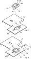
- the fixing of such a driver 14 on the cable 29 can be seen in FIGS. 2 and 3.
- the driver 14 has a plate-shaped base element 19, on which a receptacle, not shown, for the window pane 9 is arranged.
- the plate-shaped base element 19 has a recess 21, into which a clamping piece 20 designed as a clip can be clipped on. This can be done, for example, by the fact that 20 locking lugs 27 are formed on the clamping piece.
- the clamping piece 20 has a chamber 24 for receiving a holding element 30 which is fixedly connected to the cable 29.
- the holding element 30, which is designed in the form of a nipple, is preferably made of metal and is pressed immovably on the cable 29.
- the connection between the cable 29 and the window pane 9 takes place in that the cable 29 with the nipple 30 is looped through from below through the recess 21 of the basic element 19 in accordance with the representation of the plate-shaped basic element 19 in FIGS. 2 and 3.
- the nipple 30 is then inserted into the chamber 24 of the clamping piece 20, the cable sections extending on both sides of the nipple 30 being inserted into the openings 25 on the end faces of the clamping piece 20.
- the clamping piece 20 is pressed into the recess 21 of the base element 19, the rope sections extending on both sides of the nipple 30 being guided into the slots 22 provided in the base element 19 without the rope 29 being damaged.
- the rope 29 is immovably connected to the driver 14 and thus also the window 9 with the power window drive.
- the rope 29 initially has a certain amount of slack so that it can be looped over the deflection rollers 16 in a simple manner. After installing the rope 29, however, the lots must be removed again to ensure proper operation.
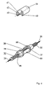
- a cable length adjusting device is inserted into the cable pull 15 according to FIGS. 4 and 5.
- the outer tube 32 of the cable 15 is interrupted and a base body 33 is inserted between the two ends of the protective tube 32.
- the base body 33 has one Bore 35 for the cable pull 15 with a longitudinal slot 38 for inserting a spacer 39 between the front ends of the outer tube 32 formed by the separation point.
- the cable 29 is of such a length that it can easily be laid over the deflection rollers 16.
- the protective tube 32 of the cable 15 is inserted into the longitudinal slot 38 of the base body 33 and is in contact with the stop 37 of the bore 35.
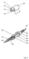
- the piece of protective tube 32 lying in the longitudinal slot 38 is pulled out of the longitudinal slot, so that only the rope 29 is present here, as is shown schematically in FIG.
- the spacer 39 is then placed between the two stop shoulders 36 on the base body 33 in such a way that the cable 29 lies in the longitudinal groove 42 formed on a web-shaped extension 41 of the spacer 39.
- the wall extensions 40 of the spacer 39 which is made of plastic, yield elastically in order to finally enclose the retraction on the base body 33 formed by the stop shoulders 36, i. w. complete flush with the stop shoulders 36. In this way, an unwanted detachment of the spacer 39 from the base body 33 is avoided.
- spacers 39 of different length L are also possible to use in order to compensate for additional tolerances.
- the spacer 39 is held by the cable tension and the associated contact pressure against its end face in the axial stop position on the stop 36 of the base body 37.
Abstract
Description
- Die Erfindung bezieht sich auf einen Seilzug-Fensterheber gemäß dem Oberbegriff des Anspruches 1.
- Aus der FR-PS 11 99 784 ist bereits ein derartiger Seilzug-Fensterheber bekannt. Dieser Fensterheber weist eine Antriebseinheit für das Seil des Seilzuges auf, welches mittels Umlenkteilen über eine vertikale Strecke geführt und in diesem Abschnitt mit einem Mitnehmer, der die Fensterscheibe hält, verbunden ist. Der Mitnehmer weist keine separate Führung auf und ist mittels eines Klemmstücks an dem Seilzug festgelegt. Insbesondere ist die Art der Verbindung zwischen Mitnehmer und Seilzug bei dieser bekannten Ausführungsform konstruktiv aufwendig, wobei zusätzlich die Gefahr eines unbeabsichtigten Lösens der Verbindung zwischen Seilzug und Mitnehmer besteht.
- Ein weiterer Seilzug-Fensterheber ist aus der US-A-4 920 697 bekannt. Hierbei ist ein Querträger, der mit der Fensterscheibe verbunden ist, vorgesehen, der beidends mit Mitnehmern verbunden ist, die ihrerseits an dem Seilzug befestigt sind.
- Die DE 40 15 774 A1 offenbar eine Fensterstellvorrichtung mit einem mittels eines Seilzuges auf und ab bewegbaren Halter, der mit der Fensterscheibe verbunden ist. Der Halter ist nicht nur mit dem Seilzug verbunden, sondern auch mittels einer Führungsrolle in einer Führungsschiene geführt. Zur Verbindung des Halters mit dem Seilzug ist ein Verbindungsstück mit einer Aufnahmevertiefung vorgesehen, in die ein am Seilzug befestigtes Klemmstück einbringbar ist. Das Verbindungsstück wird an dem Halter dadurch befestigt, daß ein an dem Verbindungsstück vorgesehener Zapfen durch eine Bohrung des Halters hindurchgesteckt und gesichert wird. Für ungeführte, lediglich am Seilzug befestigte Halter besteht bei dieser Ausführungsform die Gefahr, daß der Seilzug unbeabsichtigt aus dem Verbindungsstück austritt, wodurch die Fensterstellvorrichtung funktionsunfähig wird.
- Aus der DE 37 27 153 A1 ist ein Seilzug-Fensterheber für Kraftfahrzeuge bekannt, welcher eine Antriebseinheit mit zwei Abgängen für das Seil aufweist, das endlos in zwei sich kreuzenden Schleifen verlegt ist. Das Seil ist über vier Umlenkrollen oder -bögen geführt, welche an den Eckbereichen von zwei im Abstand voneinander angeordneten Führungsschienen montiert sind. An den Führungsschienen sind Mitnehmerplatten für die Fensterscheibe formschlüssig gleitend geführt, an welchen der die Fensterscheibe bewegende Seilzug angreift. Die Scheibe selbst ist mit ihren Stirnkanten in weiteren Führungen der Tür geführt, wie dies bspw. aus der DE 39 21 289 C1 bekannt ist. Nachteilig hierbei ist der konstruktive Aufwand und vor allem die Überbestimmung der Scheibenführung insgesamt, da die Führungen des Fensterhebers bzw. der Mitnehmer und die Scheibenführungen exakt aufeinander abgestimmt sein müssen.
- Demgegenüber liegt der Erfindung die Aufgabe zugrunde, einen Seilzug-Fensterheber der eingangs genannten Art dahingehend weiterzubilden, daß eine einfache Montage und sichere sowie dauerhafte Festlegung des Seilzuges an dem Mitnehmer gewährleistet ist.
- Diese Aufgabe wird i. w. durch einen Seilzug-Fensterheber mit den Merkmalen des Anspruchs 1 gelöst. Zum einen wird hierdurch eine besonders einfache Verbindung des Seilzugs an dem Mitnehmer dadurch erzielt, daß der Mitnehmer in eine Aussparung des plattenförmigen Grundelements einsetzbar ist, wobei die Festlegung des Mitnehmers an dem Seilzug ohne Werkzeug erfolgt. Dadurch, daß das Klemmstück eine Kammer zur Aufnahme eines fest mit dem Seilzug verbundenen Halteelements sowie an den Stirnseiten der Kammer gebildete Durchbrüche für das Seil aufweist, ist eine einfache und sichere Festlegung zwischen dem Seilzug und dem Grundelement möglich. Dabei erfolgt die Festlegung zwischen Seilzug und dem Grundelement des Mitnehmers dadurch, daß das Seil mit seinem, bspw. in Form eines Nippels ausgebildeten Halteelement durch die Aussparung des Grundelements in Art einer Schlaufe hindurchgeführt, sodann das Halteelement in die Kammer des Klemmstücks eingelegt und danach das Klemmstück in die Aussparung an dem Grundelement eingedrückt wird. Hierdurch ist das Seil unverrückbar mit dem Mitnehmer verbunden und damit die Verbindung zwischen dem Seilzug und dem Mitnehmer geschaffen. Diese besondere Art der Festlegung des Seilzuges an dem Halteelement mittels des Klemmstückes bewirkt darüber hinaus, daß ein unbeabsichtigtes Lösen des Seilzuges von dem Mitnehmer sicher vermieden ist. Da das Klemmstück von der Oberseite des Grundelements in die Aussparung einsetzbar ist, während das Seil seitlich der Kammer des Klemmstücks entlang der Unterseite des Grundelements geführt ist, ist ein unbeabsichtigtes Austreten des Seilzuges aus der Kammer des Klemmstücks nicht möglich. Desweiteren wirkt der Seilzug selbst aufgrund der speziellen Führung an dem Grundelement als Sicherung gegen ein unbeabsichtigte Austreten des Klemmstücks aus der Aussparung des Grundelements.
- Nach einer ersten besonderen Ausführungsform der Erfindung ist es vorgesehen, daß der Seilzug durch den wenigstens einen Mitnehmer endlos geführt ist. Hierdurch ist eine einfache Justiermöglichkeit zwischen der Fensterscheibe und dem an dem Seil festzulegenden Mitnehmer erreicht.
- Dadurch, daß nach einer anderen vorteilhaften Ausgestaltung der Erfindung die Umlenkteile für das Seil an den Führungsschienen für die Fensterscheibe angeordnet sind, ist der konstruktive Aufwand des Fensterhebers wesentlich reduziert. Insgesamt wird durch das Entfallen der Schienen zur Führung des oder der mit der Fensterscheibe verbundenen Mitnehmer eine Überbestimmung des Führungssystems vermieden und ein günstigeres Drehmoment des Antriebes erreicht. Ein weiterer Vorteil besteht darin, daß die von den bekannten Fensterhebern ausgehenden Geräuschproblemen infolge von Stick-Slip-Erscheinungen nicht mehr gegeben sind.
- Besonders vorteilhaft erweist sich die Maßnahme, daß das Klemmstück Rastnasen aufweist, welche das Grundelement im Bereich der Aussparung klemmend hintergreifen, wodurch die Montage des Seilzuges an dem Mitnehmer weiter verbessert wird.
- Dadurch, daß sich beidseitig der Aussparung des Grundelements Schlitze zur Hindurchführung der beidseitig aus dem Klemmstück austretenden Seilabschnitte anschließen, kann das Klemmstück zum Zwecke der Montage ohne weiteres in die Aussparung des Grundelements von der Oberseite des Grundelements eingedrückt werden, wobei die seitlich der Kammer des Klemmstücks austretenden Seilabschnitte durch die Schlitze zur Unterseite des Grundelements geführt werden. Beschädigungen des Seilzuges während der Montage werden hierdurch sicher und aus konstruktiv einfacher Weise vermieden.
- Zur Erleichterung der Montage des Fensterhebers ist eine Einstelleinrichtung für die Seillänge des Seilzuges vorgesehen mit in einer Trennstelle des Außenschlauchs des Seilzuges einsetzbarem Distanzstück. Hierdurch kann das Seil zunächst eine gewisse Lose aufweisen, um in einfacher Weise über die Umlenkteile geschlungen zu werden. Die Herausnahme der Lose nach der Montage erfolgt mittels eines Distanzstückes, das in die Trennstelle des Seilzuges zwischengesetzt wird.
- Insoweit ist es nach der Erfindung vorgesehen, daß die Einstelleinrichtung einen Grundkörper aufweist mit einer durchgehenden Bohrung für den Seilzug und einem Längsschlitz zum Einsetzen des Distanzstückes zwischen die durch die Trennstelle gebildeten stirnseitigen Enden des Außenschlauches des Seilzuges. Hierdurch ist das Einsetzen des Distanzstückes zwischen die stirnseitigen Enden des Außenschlauches wesentlich erleichtert.
- Die Handhabung läßt sich nochmals dadurch verbessern, daß die Bohrung des Grundkörpers, vorzugsweise im Bereich des Längsschlitzes einen Anschlag für den Außenschlauch des Seilzuges aufweist, so daß das Herausziehen des Außenschlauches aus dem Bereich des Längsschlitzes erleichtert ist.
- Die Festlegung des Distanzstückes an dem Grundkörper läßt sich in besonders einfacher Weise dadurch realisieren, daß das Distanzstück im Klemmsitz, bspw. mittels Rast- und Gegenrastmitteln an dem Grundkörper gehalten ist, so daß das Einsetzen des Distanzstückes ohne Werkzeuge erfolgen kann.
- Weiterhin ist es nach der Erfindung vorgesehen, daß das Distanzstück mit kreissegmentförmigen Wandungsfortsätzen den Grundkörper umfangsseitig umgreift und vorzugsweise zwischen zwei an den Grundkörper gebildeten Anlageschultern gegen axiale Verschiebung gesichert ist. Hierdurch ist in jedem Fall ein ungewolltes Ablösen des Distanzstückes vom Grundkörper vermieden.
- Nach einem weiteren Gedanken der Erfindung weist das Distanzstück einen stegförmigen Fortsatz mit einer Längsnut zur Aufnahme des Seiles auf, wobei die Stirnflächen des Fortsatzes einen Anschlag für die Enden des Schlutzschlauches des Seilzuges im Bereich der Trennstelle bilden. Hierdurch ist eine besonders stabile Anordnung der Einstelleinrichtung erreicht.
- Schließlich ist es nach der Erfindung vorgesehen, daß der Grundkörper und/oder das Distanzstück der Einstelleinrichtung und/oder das Klemmstück aus Kunststoff bestehen.
- Weitere Ziele, Vorteile, Merkmale und Anwendungsmöglichkeiten der vorliegenden Erfindung ergeben sich aus der nachfolgenden Beschreibung eines Ausführungsbeispieles anhand der Zeichnung. Dabei bilden alle beschriebenen und/oder bildlich dargestellten Merkmale für sich oder in beliebiger sinnvoller Kombination den Gegenstand der vorliegenden Erfindung, auch unabhängig von ihrer Zusammenfassung in den Ansprüchen oder deren Rückbeziehung.
- Es zeigen:
- Figur 1
- eine Ansicht der Innenseite einer Kraftfahrzeugtür mit einer möglichen Ausführungsform eines erfindungsgemäßen Fensterhebers,
- Figur 2
- eine perspektivische Ansicht einer möglichen Ausführungsform des Grundelementes des Mitnehmers mit Klemmstück,
- Figur 3
- das Grundelement mit Klemmstück gemäß Figur 2 in Montagestellung,
- Figur 4
- eine perspektivische Ansicht einer möglichen Ausführungsform einer erfindungsgemäßen Einstelleinrichtung für die Seillänge des Seilzuges mit Grundkörper und Distanzstück und
- Figur 5
- den Grundkörper und das Distanzstück gemäß Figur 4, jedoch in der Montagestellung unmittelbar vor Einsetzen des Distanzstückes.
- Die Fahrzeugtür, wie sie in Figur 1 dargestellt ist, weist einen unteren Türkasten 1 und einen oberen Fensterrahmen 2 auf. Der Türkasten 1 ist auf seiner Außenseite durch eine Türaußenhaut 3 verschlossen, während er auf der Innenseite üblicherweise mit einer Türinnenverkleidung abgedeckt ist. In der Darstellung der Figur 1 ist die Türinnenverkleidung abgenommen, so daß der in dem Türkasten 1 angeordnete Fensterheber sichtbar ist. Der Fensterrahmen 2 besitzt ein oberes Rahmenteil 4, ein hinteres Rahmenteil 5 und ein vorderes Rahmenteil 6. Die dargestellte Tür ist üblicherweise an ihrer vorderen Seite 7 mit einer Haltesäule eines Fahrzeugs über nicht dargestellte Scharniere schwenkbar befestigt, während an der hinteren Seite 8 ein nicht dargestellte Türschloßteil vorhanden ist.
- Der Fensterrahmen 2 nimmt eine an seine Umfangskontur angepaßte Fensterscheibe 9 auf, die in der Darstellung der Figur 1 etwa zur Hälfte geöffnet ist. Die Fensterscheibe 9 wird an ihrer vorderen Kante 10 und an ihrer hinteren Kante 11 jeweils in einer vorderen und einer hinteren Führungsschiene 12, 13 geführt. An der unteren Kante der Fensterscheibe 9 ist bei dem hier gewählten Ausführungsbeispiel jeweils im Bereich der Ecke ein Mitnehmer 14 aufgeklemmt, an dem das Seil 29 eines Seilzuges 15 befestigt ist. Der Seilzug 15 ist über vier Umlenkteile in Form von Umlenkrollen 16 geführt, die innerhalb des Türkastens 1 am oberen und unteren Ende der beiden Führungsschienen 12, 13 befestigt sind. Der Seilzug 15 verläuft, kreuzweise über die Umlenkrollen 16 geführt, zu einer Welle 17 einer nicht gezeigten Fensterkurbel oder eines elektrischen Antriebes hin. Je nach Drehrichtung der Welle 17 wird das Seil 29 in die eine bzw. die andere Richtung gezogen, so daß sich über die Mitnehmer 14 die Fensterscheibe 9 nach oben oder nach unten bewegt.
- Wie aus Figur 1 ersichtlich, sind die Mitnehmer 14 ohne separate Führungen mit dem Seil 29 auf- und abbewegbar. Die Führung der Mitnehmer 14 erfolgt allein über die Fensterscheibe 9 bzw. deren Führungsschienen 12, 13. Hierdurch sind Überbestimmungen in der Scheibenführung vermieden.
- Die Festlegung eines solchen Mitnehmers 14 an dem Seil 29 ist Figuren 2 und 3 zu entnehmen. Der Mitnehmer 14 besitzt ein plattenförmiges Grundelement 19, an welchem eine nicht dargestellte Aufnahme für die Fensterscheibe 9 angeordnet ist. Das plattenförmige Grundelement 19 weist eine Aussparung 21 auf, in welche ein als clip ausgebildetes Klemmstück 20 einklipsbar ist. Dies kann bspw. dadurch erfolgen, daß an dem Klemmstück 20 Rastnasen 27 gebildet sind.
- Das Klemmstück 20 weist eine Kammer 24 zur Aufnahme eines fest mit dem Seil 29 verbundenen Halteelements 30 auf. Das in Form eines Nippels ausgebildete Halteelement 30 besteht vorzugsweise aus Metall und ist unverschiebbar auf dem Seil 29 verpreßt. Die Verbindung zwischen Seil 29 und Fensterscheibe 9 erfolgt dadurch, daß das Seil 29 mit Nippel 30 gemäß der Darstellung des plattenförmigen Grundelementes 19 in Figuren 2 und 3 von unten schlaufenförmig durch die Aussparung 21 des Grundelementes 19 hindurchgeführt wird. Sodann wird der Nippel 30 in die Kammer 24 des Klemmstückes 20 eingelegt, wobei die sich beiderseits des Nippels 30 erstreckenden Seilabschnitte in die Durchbrüche 25 an den Stirnseiten des Klemmstückes 20 einlegen. Danach wird das Klemmstück 20 in die Aussparung 21 des Grundelementes 19 eingedrückt, wobei die sich beidseitig des Nippels 30 erstreckenden Seilabschnitte in die im Grundelement 19 vorgesehenen Schlitze 22 hindurchgeführt werden, ohne daß es zu einer Beschädigung des Seiles 29 kommt. Hierdurch ist das Seil 29 unverrückbar mit dem Mitnehmer 14 verbunden und damit auch die Fensterscheibe 9 mit dem Fensterheber-Antrieb.
- Zur Erleichterung der Montage des Fensterhebers weist das Seil 29 zunächst eine gewisse Lose auf, um in einfacher Weise über die Umlenkrollen 16 geschlungen zu werden. Nach der Montage des Seiles 29 muß die Lose jedoch wieder herausgenommen werden, um einen ordnungsgemäßen Betrieb zu gewährleisten. Um eine solche zusätzliche Einstellmöglichkeit bzgl. der Länge des Seilzuges 15 bzw. des Seiles 29 zu schaffen, ist gemäß Figuren 4 und 5 in den Seilzug 15 eine Seillängen-Einstelleinrichtung eingesetzt. Hierfür wird der Außenschlauch 32 des Seilzuges 15 unterbrochen und zwischen die beiden Enden des Schutzschlauches 32 ein Grundkörper 33 eingesetzt. Der Grundkörper 33 weist eine Bohrung 35 für den Seilzug 15 auf mit einem Längsschlitz 38 zum Einsetzen eines Distanzstückes 39 zwischen die durch die Trennstelle gebildeten stirnseitigen Enden des Außenschlauches 32.
- In dem in Figur 4 gezeigten Zustand weist das Seil 29 eine solche Länge auf, daß es problemlos über die Umlenkrollen 16 herumgelegt werden kann. In diesem Montagezustand ist der Schutzschlauch 32 des Seilzuges 15 im Längsschlitz 38 des Grundkörpers 33 eingeschoben und steht an dem Anschlag 37 der Bohrung 35 an. Um von dieser Stellung ausgehend das Seil 29 zu spannen, wird das im Längsschlitz 38 einliegende Stück des Schutzschlauches 32 aus dem Längsschlitz herausgezogen, so daß hier nur noch das Seil 29 vorhanden ist, wie dies schematisch in Figur 5 dargestellt ist. Anschließend wird das Distanzstück 39 zwischen die beiden Anschlagschultern 36 derart auf den Grundkörper 33 aufgesteckt, daß das Seil 29 in der an einem stegförmigen Fortsatz 41 des Distanzstückes 39 gebildeten Längsnut 42 einliegt. Beim Einsetzen weichen die Wandungsfortsätze 40 des aus Kunststoff bestehenden Distanzstückes 39 elastisch aus, um schließlich die durch die Anschlagschultern 36 gebildete Einziehung am Grundkörper 33 umfangsseitig zu umschließen, i. w. bündig mit den Anschlagschultern 36 abzuschließen. Hierdurch ist ein ungewolltes Ablösen des Distanzstückes 39 vom Grundkörper 33 vermieden.
- Um eine unterschiedliche Längeneinstellung vornehmen zu können, ist es auch möglich, Distanzstücke 39 unterschiedlicher Länge L zu verwenden, um zusätzliche Toleranzen auszugleichen. Dabei wird das Distanzstück 39 durch die Seilspannung und den damit verbundenen Anpreßdruck gegen seine Stirnfläche in axialer Anschlagstellung an dem Anschlag 36 des Grundkörpers 37 gehalten.
Claims (12)
- Seilzug-Fensterheber für Fahrzeuge, insbesondere Kraftfahrzeuge, mit einer Antriebseinheit für das Seil (29) des Seilzuges (15), welches mittels Umlenkteilen (16) über wenigstens eine i. w. vertikale Strecke geführt und in diesem Abschnitt mit einem Mitnehmer (14) verbunden ist, an welchem die Fensterscheibe (9), vorzugsweise mit ihrem unteren Randbereich gehalten ist, wobei die Fensterscheibe (9) mit ihren Seitenrändern (10, 11) in fahrzeug- bzw. türseitig angeordneten Führungsschienen (12, 13) geführt ist, wobei sich mindestens ein Mitnehmer (14) ohne separate Führungen mit dem Seil (29) auf- und abbewegt und der Seilzug (15) mittels eines Klemmstücks (20) an dem Mitnehmer (14) gehalten ist, dadurch gekennzeichnet, daß der Mitnehmer (14) ein Grundelement (19) mit einer Aussparung (21) aufweist, in welche das mit dem Seil (29) verbindbare Klemmstück (20) von der Oberseite des Grundelements (19) einsetzbar ist, und das Klemmstück (20) eine Kammer (24) zur Aufnahme eines fest mit dem Seil verbundenen Halteelements (30) sowie an den Stirnseiten der Kammer (24) gebildete Durchbrüche (25) für das Seil (29) aufweist, wobei das Seil (29) seitlich der Kammer (24) des Klemmstücks (20) entlang der Unterseite des Grundelements (19) geführt ist.
- Fensterheber nach Anspruch 1, dadurch gekennzeichnet, daß der Seilzug (15) durch den wenigstens einen Mitnehmer (14) endlos geführt ist.
- Fensterheber nach einem der vorhergehenden Ansprüche, dadurch gekennzeichnet, daß die Umlenkteile (16) für das Seil (29) an den Führungsschienen (12, 13) für die Fensterscheibe (9) angeordnet sind.
- Fensterheber nach einem der vorhergehenden Ansprüche, dadurch gekennzeichnet, daß das Klemmstück (20) Rastnasen (27) aufweist, welche das Grundelement (19) im Bereich der Aussparung (21) klemmend hintergreifen.
- Fensterheber nach einem der vorhergehenden Ansprüche, dadurch gekennzeichnet, daß sich beidseitig der Aussparung (21) des Grundelements (19) Schlitze (22) zur Hindurchführung der beidseitig aus dem Klemmstück (20) austretenden Seilabschnitte anschließen.
- Fensterheber nach einem der vorhergehenden Ansprüche, dadurch gekennzeichnet, daß eine Einstelleinrichtung für die Seillänge des Seilzuges (15) vorgesehen ist mit in eine Trennstelle des Außenschlauches (32) des Seilzuges (15) einsetzbarem Distanzstück (39).
- Fensterheber nach Anspruch 6, dadurch gekennzeichnet, daß die Einstelleinrichtung einen Grundkörper (33) aufweist mit einer durchgehenden Bohrung (35) für den Seilzug (15) und einem Längsschlitz (38) zum Einsetzen des Distanzstückes (39) zwischen die durch die Trennstelle gebildeten stirnseitigen Enden des Außenschlauches (32) des Seilzuges (15).
- Fensterheber nach Anspruch 7, dadurch gekennzeichnet, daß die Bohrung (35), vorzugsweise im Bereich des Längsschlitzes (38), einen Anschlag (37) für den Außenschlauch (32) des Seilzuges (15) aufweist.
- Fensterheber nach Anspruch 7 oder 8, dadurch gekennzeichnet, daß das Distanzstück (39) im Klemmsitz am Grundkörper (33) gehalten ist.
- Fensterheber nach einem der Ansprüche 6 bis 9, dadurch gekennzeichnet, daß das Distanzstück (39) mit kreissegmentförmigen Wandungsfortsätzen (40) den Grundkörper (33) umfangsseitig umgreift und vorzugsweise zwischen zwei an dem Grundkörper (33) gebildeten Anlageschultern (36) gegen axiale Verschiebung gesichert ist.
- Fensterheber nach einem der Ansprüche 6 bis 10, dadurch gekennzeichnet, daß das Distanzstück (39) einen stegförmigen Fortsatz (41) mit einer Längsnut (42) zur Aufnahme des Seiles (29) aufweist, wobei die Stirnflächen des Fortsatzes (41) einen Anschlag für die Enden des Schutzschlauches (32) des Seilzuges (15) im Bereich der Trennstelle bilden.
- Fensterheber nach einem der Ansprüche 1 bis 11, dadurch gekennzeichnet, daß der Grundkörper (33) und/oder das Distanzstück (39) der Einstelleinrichtung und/oder das Klemmstück (20) aus Kunststoff bestehen.
Applications Claiming Priority (3)
| Application Number | Priority Date | Filing Date | Title |
|---|---|---|---|
| DE4321735 | 1993-06-30 | ||
| DE4321735 | 1993-06-30 | ||
| PCT/EP1994/002141 WO1995001492A1 (de) | 1993-06-30 | 1994-06-30 | Seilzug-fensterheber |
Publications (2)
| Publication Number | Publication Date |
|---|---|
| EP0706603A1 EP0706603A1 (de) | 1996-04-17 |
| EP0706603B1 true EP0706603B1 (de) | 1997-06-04 |
Family
ID=6491589
Family Applications (1)
| Application Number | Title | Priority Date | Filing Date |
|---|---|---|---|
| EP94919674A Expired - Lifetime EP0706603B1 (de) | 1993-06-30 | 1994-06-30 | Seilzug-fensterheber |
Country Status (6)
| Country | Link |
|---|---|
| EP (1) | EP0706603B1 (de) |
| BR (1) | BR9406871A (de) |
| CA (1) | CA2165473A1 (de) |
| DE (1) | DE59403041D1 (de) |
| ES (1) | ES2104395T3 (de) |
| WO (1) | WO1995001492A1 (de) |
Cited By (1)
| Publication number | Priority date | Publication date | Assignee | Title |
|---|---|---|---|---|
| DE202007014817U1 (de) * | 2007-10-22 | 2009-03-05 | Brose Fahrzeugteile Gmbh & Co. Kg, Hallstadt | Seil-Fensterheber |
Families Citing this family (8)
| Publication number | Priority date | Publication date | Assignee | Title |
|---|---|---|---|---|
| FR2814772B1 (fr) | 2000-09-29 | 2003-06-27 | Btr Sealing Systems France | Systeme d'entrainement et de guidage d'une vitre coulissante escamotable dans un caisson de carrosserie d'un vehicule automobile |
| FR2815667B1 (fr) * | 2000-10-24 | 2003-08-01 | Meritor Light Vehicle Sys Ltd | Systeme de fixation d'un leve-vitre sur une porte sans cadre de vehicule |
| FR2819285B1 (fr) * | 2001-01-11 | 2003-09-19 | Metzeler Automotive Profile | Systeme d'entrainement et de guidage d'une vitre coulissante dans un caisson de porte sans cadre d'un vehicule automobile |
| CA2445436C (en) | 2001-04-26 | 2009-06-09 | Intier Automotive Closures Inc. | Universal cable window regulator assembly for vehicles |
| GB2410855A (en) * | 2004-02-04 | 2005-08-10 | Vodafone Plc | Telecommunication system communication sessions |
| DE102005002312B4 (de) * | 2005-01-17 | 2008-02-07 | Küster Automotive Door Systems GmbH | Mitnehmer für Seilzug-Fensterheber |
| US8375691B2 (en) | 2008-06-03 | 2013-02-19 | Brose Fahrzeugteile Gmbh & Co. Kg, Coburg | Synthetic fiber rope with coupling element |
| US20130255411A1 (en) * | 2010-12-22 | 2013-10-03 | Magna Closures, Inc. | Tensioning assembly for cable drive |
Family Cites Families (5)
| Publication number | Priority date | Publication date | Assignee | Title |
|---|---|---|---|---|
| FR1199784A (fr) * | 1957-07-18 | 1959-12-16 | Nsu Werke Ag | Fenêtre à manivelle pour voitures automobiles |
| FR1516936A (fr) * | 1967-01-19 | 1968-02-05 | Dba Sa | Perfectionnements aux mécanismes de lève-glace |
| DE8120936U1 (de) * | 1981-07-16 | 1982-02-11 | Metallwerk Max Brose Gmbh & Co, 8630 Coburg | Rohrfensterheber, insbesondere fuer kraftfahrzeugfenster |
| US4920697A (en) * | 1988-11-17 | 1990-05-01 | Hoover Universal Inc. | Dual drive window regulator mechanism |
| JPH03209042A (ja) * | 1990-01-08 | 1991-09-12 | Koito Mfg Co Ltd | 昇降装置 |
-
1994
- 1994-06-30 CA CA002165473A patent/CA2165473A1/en not_active Abandoned
- 1994-06-30 WO PCT/EP1994/002141 patent/WO1995001492A1/de active IP Right Grant
- 1994-06-30 ES ES94919674T patent/ES2104395T3/es not_active Expired - Lifetime
- 1994-06-30 EP EP94919674A patent/EP0706603B1/de not_active Expired - Lifetime
- 1994-06-30 DE DE59403041T patent/DE59403041D1/de not_active Expired - Lifetime
- 1994-06-30 BR BR9406871A patent/BR9406871A/pt not_active Application Discontinuation
Cited By (1)
| Publication number | Priority date | Publication date | Assignee | Title |
|---|---|---|---|---|
| DE202007014817U1 (de) * | 2007-10-22 | 2009-03-05 | Brose Fahrzeugteile Gmbh & Co. Kg, Hallstadt | Seil-Fensterheber |
Also Published As
| Publication number | Publication date |
|---|---|
| BR9406871A (pt) | 1996-03-26 |
| DE59403041D1 (de) | 1997-07-10 |
| WO1995001492A1 (de) | 1995-01-12 |
| EP0706603A1 (de) | 1996-04-17 |
| CA2165473A1 (en) | 1995-01-12 |
| ES2104395T3 (es) | 1997-10-01 |
Similar Documents
| Publication | Publication Date | Title |
|---|---|---|
| DE4015774C2 (de) | Fensterstellvorrichtung | |
| DE3149073C2 (de) | Vorrichtung zur Führung und Betätigung eines vertikal verschiebbaren Fahrzeugfensters | |
| EP1666291B1 (de) | Fensterrollo mit vereinfachter montage | |
| DE3532104A1 (de) | Vormontierte einbaueinheit fuer schiebehebedaecher von fahrzeugen | |
| EP0706603B1 (de) | Seilzug-fensterheber | |
| DE10039841A1 (de) | Vorrichtung zum Verbinden einer ein- und ausfahrbaren Kraftfahrzeug-Fensterscheibe mit einem Antriebselement | |
| DE19728708A1 (de) | Anordnung zum Einbau eines Kabelbaums in eine Automobiltür | |
| DE102007058262A1 (de) | Führungssystem für ein Fahrzeugrollo | |
| EP0760302B1 (de) | Antriebsvorrichtung für Schiebedächer für Kraftfahrzeuge | |
| DE19981927C1 (de) | Seilzug-Fensterheber für Fahrzeuge | |
| DE19835579C2 (de) | Kabelführungseinrichtung an insbesondere einem Kraftfahrzeug | |
| DE102005030707A1 (de) | Fensterrollo für Kraftfahrzeuge mit formschlüssigem Anschlag auf dem Betätigungsglied | |
| DE10123420B4 (de) | Antrieb für ein verstellbares Schließelement eines Fahrzeugdaches | |
| DE19730269C2 (de) | Vorrichtung zum Befestigen eines ersten Teils mit einem zweiten Teil | |
| DE3805576C2 (de) | Befestigung für ein Seil-Umlenkstück an einer Führungsschiene eines Seil-Fensterhebers | |
| DE102005047978B3 (de) | Antriebsgehäuse für ein bewegbares Fahrzeugteil | |
| DE102004034144B4 (de) | Mitnehmer zur Befestigung einer Fensterscheibe eines Kraftfahrzeuges an einer Führungseinrichtung eines Fensterhebers | |
| DE102009057022B4 (de) | Vorrichtung zum Führen von Reinigungsflüssigkeit | |
| DE102009036780B4 (de) | Führungseinrichtung für eine seilzugbetätigte Verstellvorrichtung | |
| EP1985792A2 (de) | Gurtwickler für einen Rolladen | |
| DE4321616A1 (de) | Vorrichtung zum Verbinden eines Mitnehmers eines Fensterhebers mit einer Fensterscheibe | |
| DE10340196B4 (de) | Schlossmoduleinrichtung für eine Kraftfahrzeugtür | |
| DE8032764U1 (de) | Gekruemmtes abstuetzglied an bowdenzug-fensterhebern | |
| DE10123424B4 (de) | Antrieb für ein verstellbares Schließelement eines Fahrzeugdaches | |
| DE202007008049U1 (de) | Führungsbaugruppe eines Kraftfahrzeugfensterhebers |
Legal Events
| Date | Code | Title | Description |
|---|---|---|---|
| PUAI | Public reference made under article 153(3) epc to a published international application that has entered the european phase |
Free format text: ORIGINAL CODE: 0009012 |
|
| 17P | Request for examination filed |
Effective date: 19951124 |
|
| AK | Designated contracting states |
Kind code of ref document: A1 Designated state(s): DE ES FR GB |
|
| 17Q | First examination report despatched |
Effective date: 19960429 |
|
| GRAG | Despatch of communication of intention to grant |
Free format text: ORIGINAL CODE: EPIDOS AGRA |
|
| GRAH | Despatch of communication of intention to grant a patent |
Free format text: ORIGINAL CODE: EPIDOS IGRA |
|
| GRAH | Despatch of communication of intention to grant a patent |
Free format text: ORIGINAL CODE: EPIDOS IGRA |
|
| GRAA | (expected) grant |
Free format text: ORIGINAL CODE: 0009210 |
|
| AK | Designated contracting states |
Kind code of ref document: B1 Designated state(s): DE ES FR GB |
|
| GBT | Gb: translation of ep patent filed (gb section 77(6)(a)/1977) |
Effective date: 19970606 |
|
| REF | Corresponds to: |
Ref document number: 59403041 Country of ref document: DE Date of ref document: 19970710 |
|
| REG | Reference to a national code |
Ref country code: ES Ref legal event code: FG2A Ref document number: 2104395 Country of ref document: ES Kind code of ref document: T3 |
|
| ET | Fr: translation filed | ||
| PLBE | No opposition filed within time limit |
Free format text: ORIGINAL CODE: 0009261 |
|
| STAA | Information on the status of an ep patent application or granted ep patent |
Free format text: STATUS: NO OPPOSITION FILED WITHIN TIME LIMIT |
|
| PGFP | Annual fee paid to national office [announced via postgrant information from national office to epo] |
Ref country code: GB Payment date: 19980514 Year of fee payment: 5 |
|
| PGFP | Annual fee paid to national office [announced via postgrant information from national office to epo] |
Ref country code: FR Payment date: 19980518 Year of fee payment: 5 |
|
| 26N | No opposition filed | ||
| PGFP | Annual fee paid to national office [announced via postgrant information from national office to epo] |
Ref country code: ES Payment date: 19980616 Year of fee payment: 5 |
|
| PG25 | Lapsed in a contracting state [announced via postgrant information from national office to epo] |
Ref country code: GB Free format text: LAPSE BECAUSE OF NON-PAYMENT OF DUE FEES Effective date: 19990630 Ref country code: FR Free format text: THE PATENT HAS BEEN ANNULLED BY A DECISION OF A NATIONAL AUTHORITY Effective date: 19990630 |
|
| PG25 | Lapsed in a contracting state [announced via postgrant information from national office to epo] |
Ref country code: ES Free format text: THE PATENT HAS BEEN ANNULLED BY A DECISION OF A NATIONAL AUTHORITY Effective date: 19990701 |
|
| GBPC | Gb: european patent ceased through non-payment of renewal fee |
Effective date: 19990630 |
|
| REG | Reference to a national code |
Ref country code: FR Ref legal event code: ST |
|
| REG | Reference to a national code |
Ref country code: ES Ref legal event code: FD2A Effective date: 20010604 |
|
| PGFP | Annual fee paid to national office [announced via postgrant information from national office to epo] |
Ref country code: DE Payment date: 20110630 Year of fee payment: 18 |
|
| REG | Reference to a national code |
Ref country code: DE Ref legal event code: R119 Ref document number: 59403041 Country of ref document: DE Effective date: 20130101 |
|
| PG25 | Lapsed in a contracting state [announced via postgrant information from national office to epo] |
Ref country code: DE Free format text: LAPSE BECAUSE OF NON-PAYMENT OF DUE FEES Effective date: 20130101 |