EP0706016B1 - Gasheizkessel - Google Patents
Gasheizkessel Download PDFInfo
- Publication number
- EP0706016B1 EP0706016B1 EP95114855A EP95114855A EP0706016B1 EP 0706016 B1 EP0706016 B1 EP 0706016B1 EP 95114855 A EP95114855 A EP 95114855A EP 95114855 A EP95114855 A EP 95114855A EP 0706016 B1 EP0706016 B1 EP 0706016B1
- Authority
- EP
- European Patent Office
- Prior art keywords
- flow
- pockets
- gas boiler
- combustion chamber
- boiler according
- Prior art date
- Legal status (The legal status is an assumption and is not a legal conclusion. Google has not performed a legal analysis and makes no representation as to the accuracy of the status listed.)
- Expired - Lifetime
Links
- 238000002485 combustion reaction Methods 0.000 claims abstract description 35
- 238000010438 heat treatment Methods 0.000 claims abstract description 18
- 239000002184 metal Substances 0.000 claims description 6
- 230000002093 peripheral effect Effects 0.000 abstract description 23
- XLYOFNOQVPJJNP-UHFFFAOYSA-N water Substances O XLYOFNOQVPJJNP-UHFFFAOYSA-N 0.000 description 13
- 238000009835 boiling Methods 0.000 description 3
- 238000001816 cooling Methods 0.000 description 3
- 230000001133 acceleration Effects 0.000 description 1
- 210000001520 comb Anatomy 0.000 description 1
- 238000011161 development Methods 0.000 description 1
- 230000018109 developmental process Effects 0.000 description 1
- 230000000694 effects Effects 0.000 description 1
- 230000002349 favourable effect Effects 0.000 description 1
- 230000017525 heat dissipation Effects 0.000 description 1
- 238000005192 partition Methods 0.000 description 1
- 238000007789 sealing Methods 0.000 description 1
- 238000005406 washing Methods 0.000 description 1
Images


Classifications
-
- F—MECHANICAL ENGINEERING; LIGHTING; HEATING; WEAPONS; BLASTING
- F24—HEATING; RANGES; VENTILATING
- F24H—FLUID HEATERS, e.g. WATER OR AIR HEATERS, HAVING HEAT-GENERATING MEANS, e.g. HEAT PUMPS, IN GENERAL
- F24H1/00—Water heaters, e.g. boilers, continuous-flow heaters or water-storage heaters
- F24H1/22—Water heaters other than continuous-flow or water-storage heaters, e.g. water heaters for central heating
- F24H1/24—Water heaters other than continuous-flow or water-storage heaters, e.g. water heaters for central heating with water mantle surrounding the combustion chamber or chambers
- F24H1/26—Water heaters other than continuous-flow or water-storage heaters, e.g. water heaters for central heating with water mantle surrounding the combustion chamber or chambers the water mantle forming an integral body
- F24H1/28—Water heaters other than continuous-flow or water-storage heaters, e.g. water heaters for central heating with water mantle surrounding the combustion chamber or chambers the water mantle forming an integral body including one or more furnace or fire tubes
- F24H1/287—Water heaters other than continuous-flow or water-storage heaters, e.g. water heaters for central heating with water mantle surrounding the combustion chamber or chambers the water mantle forming an integral body including one or more furnace or fire tubes with the fire tubes arranged in line with the combustion chamber
-
- F—MECHANICAL ENGINEERING; LIGHTING; HEATING; WEAPONS; BLASTING
- F24—HEATING; RANGES; VENTILATING
- F24H—FLUID HEATERS, e.g. WATER OR AIR HEATERS, HAVING HEAT-GENERATING MEANS, e.g. HEAT PUMPS, IN GENERAL
- F24H9/00—Details
- F24H9/0005—Details for water heaters
- F24H9/001—Guiding means
- F24H9/0015—Guiding means in water channels
Definitions
- the invention relates to a gas boiler consisting of a water-bearing housing with upper front and lower Return connection and with arranged in the upper part of the housing combustion chamber equipped with surface burner, of whose Circumferential wall made substantially parallel to each other and vertically arranged heating gas pockets to one at the bottom Exhaust gas collection chamber arranged with exhaust gas connection lead, in the upper area of the heating gas pockets and at a distance from the peripheral wall of the combustion chamber between the heating gas pockets the one between them outflowing heat transfer medium bundling and against one Partial area of the peripheral wall directing flow guides are arranged.
- a boiler of this type is known, for example, according to EP-A-0 271 434, in which, however, the pocket packet is not attached to the peripheral wall of the combustion chamber but to the bottom thereof, and in which several horizontal partition walls are used over the entire height of the pocket packet, in order to structure the upflow space in the pockets between the pockets for the return and to ensure a targeted flow against the combustion chamber floor on the last floor.
- a gas boiler of the relevant type is also known, for example according to DE-A-43 01 804, whose pot-like combustion chambers, which, however, are oriented horizontally with their axes, are equipped with hemispherical gas surface burners, lead to an extremely compact design of the entire combustion chamber area and, in this respect, as well of the entire gas boiler, which, however, is associated with a high thermal load on the combustion chamber walls, in particular in the area of the connections of the downward heating gas draft pockets, the connection opening cross sections of which reduce the area of the combustion chamber peripheral wall which can be cooled in this area accordingly.
- the invention is therefore based on the object, gas boiler of the generic type with simple means to improve in that the high density in Connection area of the heating gas draw pockets to the peripheral wall of the combustion chamber transferred heat on the water side is dissipated and boiling noises are prevented, connected with the stipulation, from the outset for one as even as possible supply of the return in all To provide pocket gaps that when arranging a simple return connection in conventionally am water-bearing housing of the boiler is not given is.
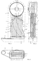
- FIG. 1 to 3 there is the gas boiler from a water-bearing housing 1 with an upper Flow connection 2 and lower return connection 3 and with arranged in the upper housing part 1 ', with surface burner 4 equipped combustion chamber 5, from its peripheral wall 6 essentially parallel and vertical to each other arranged Bankgaszugtaschen 7 to one at the bottom of the housing 1 arranged exhaust gas collection chamber 8 with exhaust gas connection 9 lead.
- Flow guides 10 arranged.
- FIG. 1 shows an embodiment in which the funnel-shaped flow guides 10 as Parts or connecting parts from the two open sides S of the pocket packet P veneered walls 14 are, with a part of the walls 14 as a flow trap 14 'is arranged above the return port 3.
- the thereby bundled, specifically to the outflow openings A guided, accelerated there and against the middle Area of the combustion chamber peripheral wall 6 directed flow of the heat transfer medium is indicated by arrows that also clarify that the whole heavily loaded lower Area of the peripheral wall 6 from the center to both Sides are rinsed intensively and thus cooled what is in this degree would not be guaranteed if the entire, return water flowing in through the return connection 3, as usual, left to itself and over the whole cross section of the aquifer and only Flow dashed housing 1 upwards could.
- the size of the outflow openings A, the inclination of the Flow guides 10 and the distance of the outflow openings A to the peripheral wall 6 can depend on the special conditions on the respective gas boiler, especially with regard to the expected maximum Thermal loads vary.
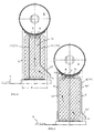
- Fig.4 are the flow guides 10 in the form of one in relation to the width B of the heating gas pockets 7 narrower Upflow shaft 12 bounding walls 13 between the Schugaszugtaschen 7 arranged, one part of the Walls 13 as a flow trap 13 'over the return port 3 is arranged, and in the embodiment of Figure 5 are of the walls W forming the flow guides 10 the return-side walls 1o 'in the pocket spaces 7 ', as shown, angled and delimit with the other walls 10 "on the return side those directed against the peripheral wall 6 of the combustion chamber 5 Outflow openings A, i.e. there is an inflow the peripheral wall parts from the side. Also at these embodiments are the ones that arise Currents indicated by arrows.
- FIG. 6 Flow guides 10 in the form of one and / or other side flank F of the Schugaszugtaschen 7 arranged Sheet metal strip 15 formed.
- the metal strips 15 are attached to the flanks F of the hot gas pockets, soldered or welded on. This is done according to FIG on both adjacent flanks of two hot gas pockets, and somewhat offset from each other, so that a kind Labyrinth as flow guide 10 arises.
- Fig. 7 can also a sealing profile on a sheet metal strip 15 15 'can be placed, or it can be used as a flow guide 10 also only one profile 16 (only schematically in FIG.
- the flow guides 10 in the form of itself Form resilient sheet metal profiles 17 and this with their edges R in guide embossments 18 of the side flanks F of the heating gas pockets 7. As from Fig. 9 recognizable and easily imaginable, this creates a real guide channel in each of the pockets.
- Fig. 12 finally illustrates an embodiment of the Flow guidance in the form of a sheet metal comb, the Engage "tines" 20 in the pocket spaces 7 ', this comb or the two combs each to the associated wall 14 is dotted or with this forms part.
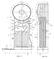
- FIGS. 13 to 16 differ from the ones described above in so far as Catching the inflowing water through a lower one Flow baffle takes place through a second flow baffle a cross flow is effected and only then a further cross flow along the bottom of the Combustion chamber peripheral wall 6 and this with increasing Increase in flow velocity.
- This embodiment has proven to be the most effective, which is why this is also preferred.
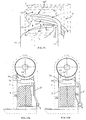
- FIGS. 16A, B A special feature is shown in FIGS. 16A, B.
- part of the relatively cold return water is branched off and fed directly to the lower cross-flow channel 24, for which purpose separate return lines 3 'are provided in (Fig. 16A) or on (Fig. 16B) housing 1, which cut out part of the return flow to a certain extent and Mix in the hot water in the cross-flow duct 24 and lower its temperature somewhat. If such a boiler is operated in the condensing mode, this is somewhat at the expense of the use of the condensing boiler. Since in the side areas 29 of the housing 1, i.e.
- small catch plates 30 can also be arranged on the side plates with access to the crossflow duct 24 or 24', respectively direct this less hot water into the cross-flow channel 24 or 24 '.
Landscapes
- Engineering & Computer Science (AREA)
- General Engineering & Computer Science (AREA)
- Chemical & Material Sciences (AREA)
- Thermal Sciences (AREA)
- Combustion & Propulsion (AREA)
- Mechanical Engineering (AREA)
- Physics & Mathematics (AREA)
- Chimneys And Flues (AREA)
- Gas Separation By Absorption (AREA)
- Treating Waste Gases (AREA)
- Adjustment Of The Magnetic Head Position Track Following On Tapes (AREA)
- Baking, Grill, Roasting (AREA)
- Incineration Of Waste (AREA)
Description
Bekannt ist auch ein Gasheizkessel einschlägiger Art bspw. nach der DE-A-43 01 804, deren topfartige Brennkammern, die mit ihrer Achse allerdings horizontal orientiert sind, mit halbkugelförmigen Gasflächenbrennern bestückt werden, führen zu einer äußerst kompakten Bauweise des ganzen Brennkammerbereiches und insofern auch des gesamten Gasheizkessels, was jedoch mit einer hohen Wärmebelastung der Brennkammerwände verbunden ist, und zwar insbesondere im Bereich der Anschlüsse der nach unten abgehenden Heizgaszugtaschen, deren Anschlußöffnungsquerschnitte die in diesem Bereich kühlbare Fläche der Brennkammerumfangswand entsprechend reduzieren. Durch diese Reduzierung der kühlbaren Brennkammerfläche gleichzeitig in Verbindung mit einer hohen Wärmebelastung und trotz der in der Regel in diesem Bereich zylindrischen Umfangswand der Brennkammer, die an sich ein Abfließen und Auflösen von Siedeblasen erwarten läßt, hat sich gezeigt, daß Siedegeräusche an derartigen Gasheizkesseln, die ansonsten an Leistung und kompakter Bauweise nichts zu wünschen übrig lassen, aufgrund der hohen Wärmebelastung nicht zu vermeiden sind.
- Fig. 1
- den Gasheizkessel in Vorderansicht;
- Fig. 2
- den Gasheizkessel gemäß Fig. 1 in Seitenansicht;
- Fig. 3
- den Gasheizkessel gemäß Fig. 1 in Draufsicht;
- Fig. 4,5
- in Vorderansicht zwei weitere Ausführungsformen des Gasheizkessels;
- Fig. 6-11
- verschiedene Ausführungsformen von Strömungsführungen im Schnitt und in Anordnung zwischen den Taschen;
- Fig. 12
- perspektivisch eine der Strömungsführungen in besonderer Ausführungsform;
- Fig. 13
- den Gasheizkessel in Vorderansicht ähnlich wie in Fig. 1 aber in anderer Ausführungsform;
- Fig. 14
- den Gasheizkessel gemäß Fig. 13 in Seitenansicht;
- Fig. 15
- perspektivisch die Strömungsleitbleche in besonderer Ausführungsform und
- Fig. 16A,B
- im Schnitt weitere besondere Ausführungsformen.
Da in den Seitenbereichen 29 des Gehäuses 1, also außerhalb der Taschenzwischenräume 7', das Wasser nicht so stark aufgeheizt wird wie in diesen, können bspw. auch kleine Fangbleche 30 an den Seitenblechen mit Zugang zum Querstromkanal 24 bzw. 24' angeordnet werden, die dieses weniger heiße Wasser in den Querstromkanal 24 bzw. 24' einlenken.
Claims (12)
- Gasheizkessel, bestehend aus einem wasserführenden Gehäuse (1) mit oberem Vor- und unterem Rücklaufanschluß (2,3) und mit im Gehäuseoberteil (1') angeordneter, mit Flächenbrenner (4) bestückter Brennkammer (5), von deren Umfangswand (6) aus zueinander im wesentlichen parallel und vertikal angeordnete Heizgaszugtaschen (7) zu einer unten am Gehäuse (1) angeordneten Abgassammelkammer (8) mit Abgasabzuganschluß (9) führen, wobei im oberen Bereich der Heizgaszugtaschen (7) und in Distanz zur Umfangswand (6) der Brennkammer (5) zwischen den Heizgaszugtaschen (7) das zwischen diesen aufströmende Wärmeträgermedium bündelnde und gegen einen Teilbereich der Umfangswand (6) richtende Strömungsführungen (10) angeordnet sind,
dadurch gekennzeichnet,
daß der Rücklaufanschluß (3) in Form eines seitlich neben dem Taschenpaket (P) in das Gehäuse (1) einragenden Rohres (3') ausgebildet und dieses mit in die Taschenzwischenräume (7') gerichteten Ausströmöffnungen (11) versehen ist. - Gasheizkessel nach Anspruch 1,
dadurch gekennzeichnet,
daß die Strömungsführungen (10) trichterförmig angeordnet und gegen den mittigen Bereich der Umfangswand (6) der Brennkammer (5) gerichtete Ausströmöffnungen (A) begrenzen. - Gasheizkessel nach Anspruch 1 oder 2,
dadurch gekennzeichnet,
daß die Strömungsführungen (10) in Form von einem in bezug auf die Breite (B) der Heizgaszugtaschen (7) schmaleren Aufströmschacht (12) begrenzenden Wänden (13) zwischen den Heizgaszugtaschen (7) angeordnet sind, wobei der eine Teil der Wände (13) als Strömungsfang (13') über dem Rücklaufanschluß (3) angeordnet ist. - Gasheizkessel nach einem der Ansprüche 1 oder 2,
dadurch gekennzeichnet,
daß die trichterförmig angeordneten Strömungsführungen (lo) als Teile oder Anschlußteile von die beiden offenen Seiten (S) des Taschenpaketes (P) verblendenden Wänden (14) ausgebildet sind, wobei der eine Teil der Wände (14) als Strömungsfang (13') über dem Rücklaufanschlag (3) angeordnet ist. - Gasheizkessel nach Anspruch 1 oder 2,
dadurch gekennzeichnet,
daß von den die Strömungsführungen (10) bildenden Wänden (W) die rücklaufseitigen Wände (10') in die Taschenzwischenräume (7') abgewinkelt sind und mit den anderen Wänden (10") auf der rücklaufabgewandten Seite gegen die Umfangswand (6) der Brennkammer (5) gerichtete Ausströmöffnungen (A) begrenzen. - Gasheizkessel nach Anspruch 1,
dadurch gekennzeichnet,
daß die Strömungsführungen (10) in Form von jeweils zwei im oberen Bereich der Heizgaszugtaschen (7) distanziert zueinander entgegengesetzt gerichteten und zur Umfangswand (6) im wesentlichen parallelen Strömungsleitblechen (21, 21') ausgebildet und angeordnet sind, die mit Seitenbegrenzungsblechen (22) des jeweils anderen Strömungsleitbleches (21,21') an gegenüberliegenden Rändern der Heizgaszugtaschen (7) befindliche Überströmöffnungen (23) zu von den Strömungsleitblechen (21,21') begrenzten Querstromkanälen (24,24') begrenzen, wobei der sich längs der Umfangswand (6) der Brennkammer (5) erstreckende Querstromkanal (24') mit einem kleineren Querschnitt bemessen ist als der darunter befindliche Querstromkanal (24). - Gasheizkessel nach Anspruch 7,
dadurch gekennzeichnet,
daß in den von den Strömungsleitblechen (21,21') und den Seitenbegrenzungsblechen (22) begrenzten Zwickeln (25) entgegengesetzt gewölbte Leitbleche (26) angeordnet und die darüber befindlichen Bereiche (27) der Strömungsleitbleche (21,21') und/oder die Seitenbegrenzungsbleche (22) mit einer Lochung (28) versehen sind. - Gasheizkessel nach Anspruch 7,
dadurch gekennzeichnet,
daß die Strömungsleitbleche (21,21'), von den Seitenbegrenzungsblechen (22) ausgehend, in ihren Ansatzbereichen ansteigend gewölbt ausgebildet sind. - Gasheizkessel nach einem der Ansprüche 6 bis 8,
dadurch gekennzeichnet,
daß die Überströmöffnungen (23) in den Taschenzwischenräumen (7') abwechselnd auf der jeweils anderen Seite angeordnet sind. - Gasheizkessel nach einem der Ansprüche 6 bis 9,
dadurch gekennzeichnet,
daß im wasserführenden Innenraum (29) oder außerhalb des Gehäuses (1) zum unteren Querstromkanal (24) führende, in diesen einmündende und vom Rücklaufanschluß (3) ausgehende Rücklaufleitungen (3') angeordnet sind. - Gasheizkessel nach einem der Ansprüche 6 bis 10,
dadurch gekennzeichnet,
daß an den Seitenbegrenzungsblechen (22) in die Seitenbereiche (29) des Gehäuses (1) ausgebogene Fangbleche (30) mit Zugang mindestens zum Querstromkanal (24) angeordnet sind. - Gasheizkessel nach einem der Ansprüche 1 bis 11,
dadurch gekennzeichnet,
daß die Strömungsführungen (10) oder die Strömungsleitbleche (21,21') in Form von auf der einen und/oder anderen Seitenflanke (F) der Heizgaszugtaschen (7) angeordneten Blechstreifen (15) oder Profilen (16) aus wasser- und wärmebeständigem Kunststoff, aus in sich federnden Blechprofilen (17) oder aus in die Zwischenräume (7') der Heizgaszugtaschen (7) weisenden Stegausprägungen (19) gebildet sind.
Applications Claiming Priority (4)
| Application Number | Priority Date | Filing Date | Title |
|---|---|---|---|
| DE4435745 | 1994-10-06 | ||
| DE19944435745 DE4435745C1 (de) | 1994-10-06 | 1994-10-06 | Gasheizkessel |
| DE29503697U DE29503697U1 (de) | 1995-03-04 | 1995-03-04 | Gasheizkessel |
| DE29503697U | 1995-03-04 |
Publications (2)
| Publication Number | Publication Date |
|---|---|
| EP0706016A1 EP0706016A1 (de) | 1996-04-10 |
| EP0706016B1 true EP0706016B1 (de) | 2001-01-10 |
Family
ID=25940805
Family Applications (1)
| Application Number | Title | Priority Date | Filing Date |
|---|---|---|---|
| EP95114855A Expired - Lifetime EP0706016B1 (de) | 1994-10-06 | 1995-09-21 | Gasheizkessel |
Country Status (3)
| Country | Link |
|---|---|
| EP (1) | EP0706016B1 (de) |
| AT (1) | ATE198658T1 (de) |
| DE (1) | DE59508954D1 (de) |
Families Citing this family (2)
| Publication number | Priority date | Publication date | Assignee | Title |
|---|---|---|---|---|
| PL229301B1 (pl) * | 2015-09-28 | 2018-07-31 | Aic Spolka Akcyjna | Opalany podgrzewacz wody |
| EP3336427B1 (de) * | 2016-12-16 | 2019-07-03 | Ikerlan, S. Coop. | Gasbrenner |
Family Cites Families (4)
| Publication number | Priority date | Publication date | Assignee | Title |
|---|---|---|---|---|
| US2388647A (en) * | 1944-10-07 | 1945-11-06 | Howard G Sawyer | Fire-tube boiler |
| FR2472725A1 (fr) * | 1979-12-27 | 1981-07-03 | Barrault Rene Louis | Chaudiere a lame d'eau et a tubes de fumees |
| EP0271434B1 (de) * | 1986-12-06 | 1992-04-29 | Joh. Vaillant GmbH u. Co. | Stahlheizkessel |
| DE9318680U1 (de) | 1993-12-07 | 1994-02-24 | Vießmann, Hans, Dr., 35088 Battenberg | Gasheizkessel |
-
1995
- 1995-09-21 EP EP95114855A patent/EP0706016B1/de not_active Expired - Lifetime
- 1995-09-21 DE DE59508954T patent/DE59508954D1/de not_active Expired - Fee Related
- 1995-09-21 AT AT95114855T patent/ATE198658T1/de not_active IP Right Cessation
Also Published As
| Publication number | Publication date |
|---|---|
| DE59508954D1 (de) | 2001-02-15 |
| EP0706016A1 (de) | 1996-04-10 |
| ATE198658T1 (de) | 2001-01-15 |
Similar Documents
| Publication | Publication Date | Title |
|---|---|---|
| DE2634603C2 (de) | Heizungs-Kessel | |
| DE4207500C2 (de) | Heizkessel mit verringerter NO¶x¶-Emission | |
| DE19854910B4 (de) | Heizkessel | |
| DE2363611B2 (de) | Reihenbrenner für gasbetriebene Heizvorrichtungen | |
| DE4425302C2 (de) | Gußeiserner Gliederheizkessel | |
| EP0706016A1 (de) | Gasheizkessel | |
| DE69207680T2 (de) | Ofen für Holz mit Glasteil und Mittel zu seiner Reinigung | |
| DE2217596A1 (de) | Umluftheizung mit geschlossenem Heizsystem | |
| DE1679192B2 (de) | Gasbeheizter luftumwaelzofen | |
| EP0915304A2 (de) | Dreizugheizkessel | |
| DE3916142C2 (de) | Atmosphärischer Gasbrenner | |
| EP0321667A1 (de) | Heizkessel | |
| DE2107108A1 (de) | Gliederkessel mit einer im unteren Teil untergebrachten Brennkammer | |
| DE4435745C1 (de) | Gasheizkessel | |
| DE8605274U1 (de) | Gasbrenner | |
| DE4022730A1 (de) | Heizgaszugtasche | |
| DE19505235B4 (de) | Brennwertkessel | |
| DE29503697U1 (de) | Gasheizkessel | |
| DE69404723T2 (de) | Rauchabzugsgerät insbesondere für Schornsteine und Kamine | |
| DE20021089U1 (de) | Kassettenofen | |
| EP0392150B1 (de) | Backofen mit Heizgasumwälzheizung | |
| DE2743959C2 (de) | ||
| EP1288586B1 (de) | Gusseisener Gliederheizkessel | |
| DE69918129T2 (de) | Kessel | |
| DE3039866A1 (de) | Bausatz fuer feuerungen |
Legal Events
| Date | Code | Title | Description |
|---|---|---|---|
| PUAI | Public reference made under article 153(3) epc to a published international application that has entered the european phase |
Free format text: ORIGINAL CODE: 0009012 |
|
| AK | Designated contracting states |
Kind code of ref document: A1 Designated state(s): AT BE DE ES FR IT NL |
|
| 17P | Request for examination filed |
Effective date: 19961002 |
|
| 17Q | First examination report despatched |
Effective date: 19990323 |
|
| GRAG | Despatch of communication of intention to grant |
Free format text: ORIGINAL CODE: EPIDOS AGRA |
|
| GRAG | Despatch of communication of intention to grant |
Free format text: ORIGINAL CODE: EPIDOS AGRA |
|
| GRAH | Despatch of communication of intention to grant a patent |
Free format text: ORIGINAL CODE: EPIDOS IGRA |
|
| GRAH | Despatch of communication of intention to grant a patent |
Free format text: ORIGINAL CODE: EPIDOS IGRA |
|
| GRAA | (expected) grant |
Free format text: ORIGINAL CODE: 0009210 |
|
| AK | Designated contracting states |
Kind code of ref document: B1 Designated state(s): AT BE DE ES FR IT NL |
|
| PG25 | Lapsed in a contracting state [announced via postgrant information from national office to epo] |
Ref country code: NL Free format text: LAPSE BECAUSE OF FAILURE TO SUBMIT A TRANSLATION OF THE DESCRIPTION OR TO PAY THE FEE WITHIN THE PRESCRIBED TIME-LIMIT Effective date: 20010110 Ref country code: IT Free format text: LAPSE BECAUSE OF FAILURE TO SUBMIT A TRANSLATION OF THE DESCRIPTION OR TO PAY THE FEE WITHIN THE PRESCRIBED TIME-LIMIT;WARNING: LAPSES OF ITALIAN PATENTS WITH EFFECTIVE DATE BEFORE 2007 MAY HAVE OCCURRED AT ANY TIME BEFORE 2007. THE CORRECT EFFECTIVE DATE MAY BE DIFFERENT FROM THE ONE RECORDED. Effective date: 20010110 Ref country code: ES Free format text: THE PATENT HAS BEEN ANNULLED BY A DECISION OF A NATIONAL AUTHORITY Effective date: 20010110 |
|
| REF | Corresponds to: |
Ref document number: 198658 Country of ref document: AT Date of ref document: 20010115 Kind code of ref document: T |
|
| REF | Corresponds to: |
Ref document number: 59508954 Country of ref document: DE Date of ref document: 20010215 |
|
| ET | Fr: translation filed | ||
| NLV1 | Nl: lapsed or annulled due to failure to fulfill the requirements of art. 29p and 29m of the patents act | ||
| PG25 | Lapsed in a contracting state [announced via postgrant information from national office to epo] |
Ref country code: AT Free format text: LAPSE BECAUSE OF NON-PAYMENT OF DUE FEES Effective date: 20010921 |
|
| PG25 | Lapsed in a contracting state [announced via postgrant information from national office to epo] |
Ref country code: BE Free format text: LAPSE BECAUSE OF NON-PAYMENT OF DUE FEES Effective date: 20010930 |
|
| PLBE | No opposition filed within time limit |
Free format text: ORIGINAL CODE: 0009261 |
|
| STAA | Information on the status of an ep patent application or granted ep patent |
Free format text: STATUS: NO OPPOSITION FILED WITHIN TIME LIMIT |
|
| 26N | No opposition filed | ||
| BERE | Be: lapsed |
Owner name: VIESSMANN WERKE G.M.B.H. & CO. Effective date: 20010930 |
|
| PG25 | Lapsed in a contracting state [announced via postgrant information from national office to epo] |
Ref country code: DE Free format text: LAPSE BECAUSE OF NON-PAYMENT OF DUE FEES Effective date: 20020501 |
|
| PG25 | Lapsed in a contracting state [announced via postgrant information from national office to epo] |
Ref country code: FR Free format text: LAPSE BECAUSE OF NON-PAYMENT OF DUE FEES Effective date: 20020531 |
|
| REG | Reference to a national code |
Ref country code: FR Ref legal event code: ST |