EP0706014B1 - Hitzeschutzschild für Wärmetauscher - Google Patents
Hitzeschutzschild für Wärmetauscher Download PDFInfo
- Publication number
- EP0706014B1 EP0706014B1 EP95111715A EP95111715A EP0706014B1 EP 0706014 B1 EP0706014 B1 EP 0706014B1 EP 95111715 A EP95111715 A EP 95111715A EP 95111715 A EP95111715 A EP 95111715A EP 0706014 B1 EP0706014 B1 EP 0706014B1
- Authority
- EP
- European Patent Office
- Prior art keywords
- heat
- protection shield
- heat protection
- pipe
- heat exchanger
- Prior art date
- Legal status (The legal status is an assumption and is not a legal conclusion. Google has not performed a legal analysis and makes no representation as to the accuracy of the status listed.)
- Expired - Lifetime
Links
- 238000002485 combustion reaction Methods 0.000 abstract description 3
- 238000010438 heat treatment Methods 0.000 abstract 1
- 239000007789 gas Substances 0.000 description 4
- 230000007704 transition Effects 0.000 description 2
- 241001156002 Anthonomus pomorum Species 0.000 description 1
- 230000015572 biosynthetic process Effects 0.000 description 1
- 239000000567 combustion gas Substances 0.000 description 1
- 238000001816 cooling Methods 0.000 description 1
- 238000005336 cracking Methods 0.000 description 1
- 239000011810 insulating material Substances 0.000 description 1
- 239000011214 refractory ceramic Substances 0.000 description 1
- 239000011819 refractory material Substances 0.000 description 1
- 239000011343 solid material Substances 0.000 description 1
- 238000003786 synthesis reaction Methods 0.000 description 1
- 230000008646 thermal stress Effects 0.000 description 1
- 238000003466 welding Methods 0.000 description 1
Images
Classifications
-
- F—MECHANICAL ENGINEERING; LIGHTING; HEATING; WEAPONS; BLASTING
- F24—HEATING; RANGES; VENTILATING
- F24C—DOMESTIC STOVES OR RANGES ; DETAILS OF DOMESTIC STOVES OR RANGES, OF GENERAL APPLICATION
- F24C15/00—Details
- F24C15/32—Arrangements of ducts for hot gases, e.g. in or around baking ovens
- F24C15/322—Arrangements of ducts for hot gases, e.g. in or around baking ovens with forced circulation
-
- F—MECHANICAL ENGINEERING; LIGHTING; HEATING; WEAPONS; BLASTING
- F24—HEATING; RANGES; VENTILATING
- F24C—DOMESTIC STOVES OR RANGES ; DETAILS OF DOMESTIC STOVES OR RANGES, OF GENERAL APPLICATION
- F24C15/00—Details
Definitions
- the invention relates to a heat shield made of solid material for heat exchangers with at least one burner chamber into which the open ends of heat exchanger tubes open out, openings in the heat protection shield at the Places are provided at which the heat exchanger tubes in the burner chamber open out and within the heat shield separating cuts or dividing lines are provided, the areas around the respective openings at least partially separate from each other.
- Heat shields are used, for example, in gas-heated burner chambers Cookers used.
- the structure of such a stove is for example in EP-A-551 807.
- the kitchen stove described there has an oven space through which the heat exchanger tubes pass. These heat exchanger tubes open ends in one below the furnace space arranged burner chamber. Gas burners are arranged in the burner chamber, whose hot combustion gases are passed through the heat exchanger tubes become.
- the object of the present invention is to provide heat shields for heat exchangers the genus specified at the outset, in which heat-related Tensions can largely be reduced.
- this object is achieved with a generic heat protection shield made of refractory material, such as refractory ceramic, through the Features of the characterizing part of claim 1 solved. So that's it Heat shield not in contact with the walls of the combustion chamber, and connecting pipes extend at the edge of the openings of the heat protection shield, a in the end region of the connecting pipes and / or the heat exchanger pipes Socket pipe is arranged. As a result, heat-related tensions in the Heat protection shields directly impacted by the burner flames and in Transition area between connection and heat exchanger pipe more easily dismantled.
- the connection pipes are basically the same to the respective in the assembled state Heat exchanger tubes aligned that the longitudinal axes of the connecting tubes as well of the respective heat exchanger tubes match. The connection can to the respective heat exchanger tubes in different ways.
- the heat shield separating cuts may be provided between the individual openings in such a way that the heat-related deformations of the heat shield are canceled or be reduced.
- the separating cuts can run around the respective entire opening, so that the form separate plates around the opening of the heat protection shield.
- the non-interconnected plates of the heat protection shield can according to a preferred embodiment of the invention hung separately from each other be.
- the individual panels can form one level when assembled.
- the individual plates can be attached to the respective heat exchanger tubes their openings belong to be hung.
- the individual plates can also be used be suspended from the edges of the respective connecting pipes. According to a preferred
- the individual plates are attached to the respective heat exchanger tubes are hung, tapered so that they are a lampshade protrude straight into the burner chamber.
- the heat shield can consist of two superimposed shields, but they stand alone have the features of the invention.
- the connecting pipe in installed position inserted into the associated heat exchanger tube be, the connecting pipe with its outer wall on the inner wall of the heat exchanger tube, but its longitudinal displaceability remains guaranteed in the heat exchanger tube.
- the connecting pipe and the end of the associated heat exchanger pipe can also have the same diameter and separate from each other and with each other be arranged in alignment, both through the sleeve pipe according to the invention are surrounded, which thus forms the connection between the two tubes.
- Either the connecting pipe or the end of the associated heat exchanger pipe or both can also be longitudinally displaceable in the socket pipe be stored.
- the connecting pipe can be assembled State in the respectively assigned heat exchanger tube to form a Annular gap between the outer surface of the connecting pipe and the inner surface of the heat exchanger tube.
- Another alternative embodiment may consist in that the connecting pipe has a larger diameter than the heat exchanger tube and thus lies outside the end of the respectively assigned heat exchanger tube. Also an annular gap is then formed here, which, however, is between the outer circumference of the heat exchanger tube and the inner circumference of the connecting tube extends.
- the heat protection shield consists of two shields lying on top of each other, it is possible that the separating cuts or lines of these two superimposed Layers are not congruent, but cross each other.
- the connecting pipes can be above the heat shield as well as below the heat shield, in relation to the position of the Brenners, start.
- the heat shield according to the invention can not only in kitchen stoves, but also generally in burner chambers of boilers or, for example, in gas-heated ones Find hotplates application.
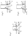
- the heat shield 20 also forms the cover the burner chamber.
- the heat shield could also be used in the same way be moved into the burner chamber.
- a connecting pipe 18 is on the plate 26 of the heat shield 20 attached.
- This connecting tube 18 is coaxial with one Heat exchanger tube 32 aligned, with its free end approximately with that Floor 34 of the furnace space closes.
- the opening of the furnace floor 34 is bent over at the edge, as is shown in more detail in FIG. 1.
- a crack Between two coaxially arranged pipe sections which have the same diameter, is left a crack. This is from a sleeve pipe 36, which is bent on the Edge of the furnace floor 34 is welded, bridged.
- the connecting pipe has an outer diameter of approximately corresponds to the inside diameter of the heat exchanger tube.
- the connecting pipe can be inserted into the heat exchanger pipe, whereby the respective diameters of the pipes can be coordinated with one another, that the connecting pipe within the heat exchanger pipe, for example thermal expansion, can expand.
- the outer diameter of the Connection tube has a smaller diameter than the inner diameter of the heat exchanger tube. In this case there remains after inserting the connecting pipe into the heat exchanger tube between the outside diameter of the Connection pipe and the heat exchanger pipe an annular gap.
- FIG. 2 largely corresponds to that according to the Fig. 1.
- a sleeve pipe 36 is also arranged here. However, here is the diameter of the connecting tube 18 chosen larger than the outer diameter of the Heat exchanger tube 32 or the sleeve tube 36 surrounding this end. The difference in diameter is chosen so that an annular gap between the Outside diameter of the sleeve pipe 36 and the inside diameter of the connecting pipe 18 remains, as shown in Fig. 2.
- FIG. 3 largely corresponds to that according to FIG. 2.
- the heat shield made of two shields lying on top of each other educated.
- the connecting tubes 18 form with the heat shield 20 an integral unit.
Landscapes
- Engineering & Computer Science (AREA)
- Chemical & Material Sciences (AREA)
- Combustion & Propulsion (AREA)
- Mechanical Engineering (AREA)
- General Engineering & Computer Science (AREA)
- Heat-Exchange Devices With Radiators And Conduit Assemblies (AREA)
- Air Filters, Heat-Exchange Apparatuses, And Housings Of Air-Conditioning Units (AREA)
- Details Of Fluid Heaters (AREA)
Applications Claiming Priority (2)
| Application Number | Priority Date | Filing Date | Title |
|---|---|---|---|
| DE9416203U DE9416203U1 (de) | 1994-10-07 | 1994-10-07 | Hitzeschutzschild für Wärmetauscher |
| DE9416203U | 1994-10-07 |
Publications (2)
| Publication Number | Publication Date |
|---|---|
| EP0706014A1 EP0706014A1 (de) | 1996-04-10 |
| EP0706014B1 true EP0706014B1 (de) | 1999-10-20 |
Family
ID=6914635
Family Applications (1)
| Application Number | Title | Priority Date | Filing Date |
|---|---|---|---|
| EP95111715A Expired - Lifetime EP0706014B1 (de) | 1994-10-07 | 1995-07-25 | Hitzeschutzschild für Wärmetauscher |
Country Status (6)
| Country | Link |
|---|---|
| EP (1) | EP0706014B1 (da) |
| AT (1) | ATE185890T1 (da) |
| DE (2) | DE9416203U1 (da) |
| DK (1) | DK0706014T3 (da) |
| ES (1) | ES2138689T3 (da) |
| GR (1) | GR3032448T3 (da) |
Families Citing this family (1)
| Publication number | Priority date | Publication date | Assignee | Title |
|---|---|---|---|---|
| US9372005B2 (en) | 2012-11-30 | 2016-06-21 | Alto-Shaam, Inc. | Heat exchanger for oven |
Family Cites Families (6)
| Publication number | Priority date | Publication date | Assignee | Title |
|---|---|---|---|---|
| US3707186A (en) * | 1971-01-18 | 1972-12-26 | Foster Wheeler Corp | Cooling tube ferrule |
| DD239465A1 (de) * | 1985-07-18 | 1986-09-24 | Kali Veb K | Vorrichtung zur verschleissminderung suspensionsdurchstroemter rohrbuendelwaermeaustauscher |
| FR2661244B1 (fr) * | 1990-04-19 | 1994-08-05 | Olifan Vibracim Sa | Embout de protection pour tube de chaudiere et son procede de fabrication. |
| IT229213Y1 (it) | 1992-01-08 | 1998-07-02 | Lainox Srl | Perfezionamento della camera di combustione particolarmente nei forni a convenzione forzata per la cottura di vivande |
| EP0567674B1 (de) * | 1992-04-29 | 1994-02-23 | Deutsche Babcock-Borsig Aktiengesellschaft | Wärmetauscher zum Kühlen von in einer Kohlevergasungsanlage erzeugtem Synthesegas |
| DE4239689A1 (de) * | 1992-11-26 | 1994-06-01 | Wiesheu Gmbh | Wärmetauscher mit Flammbeheizung |
-
1994
- 1994-10-07 DE DE9416203U patent/DE9416203U1/de not_active Expired - Lifetime
-
1995
- 1995-07-25 ES ES95111715T patent/ES2138689T3/es not_active Expired - Lifetime
- 1995-07-25 AT AT95111715T patent/ATE185890T1/de not_active IP Right Cessation
- 1995-07-25 DK DK95111715T patent/DK0706014T3/da active
- 1995-07-25 DE DE59507088T patent/DE59507088D1/de not_active Expired - Fee Related
- 1995-07-25 EP EP95111715A patent/EP0706014B1/de not_active Expired - Lifetime
-
2000
- 2000-01-20 GR GR20000400143T patent/GR3032448T3/el not_active IP Right Cessation
Also Published As
| Publication number | Publication date |
|---|---|
| ES2138689T3 (es) | 2000-01-16 |
| DE9416203U1 (de) | 1994-12-01 |
| ATE185890T1 (de) | 1999-11-15 |
| GR3032448T3 (en) | 2000-05-31 |
| DK0706014T3 (da) | 2000-01-03 |
| EP0706014A1 (de) | 1996-04-10 |
| DE59507088D1 (de) | 1999-11-25 |
Similar Documents
| Publication | Publication Date | Title |
|---|---|---|
| DE2660373B1 (de) | Fluiddurchstroemtes Kuehlelement | |
| DE1751586A1 (de) | Mit Zapfen versehene Waermeaustauscherrohre | |
| DE4207048C1 (en) | Double wall exhaust pipe for IC engine - has two types of tube sections, with different profiles, with c-profile sections supported on stop edges of inner wall | |
| EP0706014B1 (de) | Hitzeschutzschild für Wärmetauscher | |
| DE2110197A1 (de) | Ofen zum Erhitzen von Flüssigkeiten oder Gasen | |
| EP2573480B1 (de) | Vorrichtung zum Aufheizen eines Wärmeträgers für insbesondere Wäschereimaschinen | |
| EP0599103B1 (de) | Wärmetauscher mit Flammbeheizung und Verfahren zu dessen Herstellung | |
| DE1168929B (de) | Rohrfoermiges Waermetauscherelement | |
| DE69300224T2 (de) | Kocher zum Garen von Speisen mit erzwungener Konvektion. | |
| DE3124263A1 (de) | Auskleidung fuer einen im querscchnitt zumindest angenaehert runden feuerungsraum | |
| DE10041472C1 (de) | Gasstrahlungsbrenner | |
| DE69203410T2 (de) | Isolierrohr für eine Kaminleitung. | |
| DE10015343C2 (de) | Abhitzkessel mit in einer Rohrplatte verschweißten Heizflächenrohren | |
| DE3128601A1 (de) | Roehrenofen | |
| DE19745768C2 (de) | Gargerät, insbesondere ein mittels Lochbrennern gasbeheiztes Grillgerät | |
| DE3715540C2 (da) | ||
| DE9416205U1 (de) | Verbindung von Gaswärmetauscherrohren mit einem Lochboden | |
| DE2149840C3 (de) | Warmwasser-Heizkessel für eine Sammelheizungsanlage | |
| DE2115522C3 (de) | Durchlauferhitzer mit einem Brenner | |
| DE2025472C3 (de) | Heizungskessel | |
| EP0292580A1 (de) | Heizkessel | |
| CH425140A (de) | Gliederheizkessel für flüssige und gasförmige Brennstoffe | |
| DE69200149T2 (de) | Gasbetriebener Wasserrohrkessel. | |
| DE7809548U1 (de) | Gasbrenner | |
| DE1907413A1 (de) | Warmwasserheizung |
Legal Events
| Date | Code | Title | Description |
|---|---|---|---|
| PUAI | Public reference made under article 153(3) epc to a published international application that has entered the european phase |
Free format text: ORIGINAL CODE: 0009012 |
|
| AK | Designated contracting states |
Kind code of ref document: A1 Designated state(s): AT BE CH DE DK ES FR GB GR IE IT LI LU MC NL PT SE |
|
| 17P | Request for examination filed |
Effective date: 19960306 |
|
| 17Q | First examination report despatched |
Effective date: 19970502 |
|
| GRAG | Despatch of communication of intention to grant |
Free format text: ORIGINAL CODE: EPIDOS AGRA |
|
| GRAG | Despatch of communication of intention to grant |
Free format text: ORIGINAL CODE: EPIDOS AGRA |
|
| GRAH | Despatch of communication of intention to grant a patent |
Free format text: ORIGINAL CODE: EPIDOS IGRA |
|
| GRAH | Despatch of communication of intention to grant a patent |
Free format text: ORIGINAL CODE: EPIDOS IGRA |
|
| RAP1 | Party data changed (applicant data changed or rights of an application transferred) |
Owner name: ANGELO PO GRANDI CUCINE S.P.A. |
|
| GRAA | (expected) grant |
Free format text: ORIGINAL CODE: 0009210 |
|
| AK | Designated contracting states |
Kind code of ref document: B1 Designated state(s): AT BE CH DE DK ES FR GB GR IE IT LI LU MC NL PT SE |
|
| REF | Corresponds to: |
Ref document number: 185890 Country of ref document: AT Date of ref document: 19991115 Kind code of ref document: T |
|
| REG | Reference to a national code |
Ref country code: CH Ref legal event code: EP |
|
| REG | Reference to a national code |
Ref country code: CH Ref legal event code: NV Representative=s name: BOVARD AG PATENTANWAELTE |
|
| REF | Corresponds to: |
Ref document number: 59507088 Country of ref document: DE Date of ref document: 19991125 |
|
| GBT | Gb: translation of ep patent filed (gb section 77(6)(a)/1977) |
Effective date: 19991112 |
|
| REG | Reference to a national code |
Ref country code: DK Ref legal event code: T3 |
|
| ITF | It: translation for a ep patent filed | ||
| REG | Reference to a national code |
Ref country code: ES Ref legal event code: FG2A Ref document number: 2138689 Country of ref document: ES Kind code of ref document: T3 |
|
| REG | Reference to a national code |
Ref country code: IE Ref legal event code: FG4D Free format text: GERMAN |
|
| REG | Reference to a national code |
Ref country code: PT Ref legal event code: SC4A Free format text: AVAILABILITY OF NATIONAL TRANSLATION Effective date: 19991022 |
|
| ET | Fr: translation filed | ||
| PGFP | Annual fee paid to national office [announced via postgrant information from national office to epo] |
Ref country code: MC Payment date: 20000620 Year of fee payment: 6 |
|
| PGFP | Annual fee paid to national office [announced via postgrant information from national office to epo] |
Ref country code: GR Payment date: 20000630 Year of fee payment: 6 |
|
| PGFP | Annual fee paid to national office [announced via postgrant information from national office to epo] |
Ref country code: PT Payment date: 20000706 Year of fee payment: 6 |
|
| PGFP | Annual fee paid to national office [announced via postgrant information from national office to epo] |
Ref country code: NL Payment date: 20000718 Year of fee payment: 6 Ref country code: LU Payment date: 20000718 Year of fee payment: 6 Ref country code: BE Payment date: 20000718 Year of fee payment: 6 Ref country code: AT Payment date: 20000718 Year of fee payment: 6 |
|
| PGFP | Annual fee paid to national office [announced via postgrant information from national office to epo] |
Ref country code: SE Payment date: 20000720 Year of fee payment: 6 Ref country code: DK Payment date: 20000720 Year of fee payment: 6 |
|
| PGFP | Annual fee paid to national office [announced via postgrant information from national office to epo] |
Ref country code: IE Payment date: 20000727 Year of fee payment: 6 |
|
| PGFP | Annual fee paid to national office [announced via postgrant information from national office to epo] |
Ref country code: CH Payment date: 20000802 Year of fee payment: 6 |
|
| PLBE | No opposition filed within time limit |
Free format text: ORIGINAL CODE: 0009261 |
|
| STAA | Information on the status of an ep patent application or granted ep patent |
Free format text: STATUS: NO OPPOSITION FILED WITHIN TIME LIMIT |
|
| 26N | No opposition filed | ||
| PG25 | Lapsed in a contracting state [announced via postgrant information from national office to epo] |
Ref country code: LU Free format text: LAPSE BECAUSE OF NON-PAYMENT OF DUE FEES Effective date: 20010725 Ref country code: IE Free format text: LAPSE BECAUSE OF NON-PAYMENT OF DUE FEES Effective date: 20010725 Ref country code: DK Free format text: LAPSE BECAUSE OF NON-PAYMENT OF DUE FEES Effective date: 20010725 Ref country code: AT Free format text: LAPSE BECAUSE OF NON-PAYMENT OF DUE FEES Effective date: 20010725 |
|
| PG25 | Lapsed in a contracting state [announced via postgrant information from national office to epo] |
Ref country code: SE Free format text: LAPSE BECAUSE OF NON-PAYMENT OF DUE FEES Effective date: 20010726 |
|
| PG25 | Lapsed in a contracting state [announced via postgrant information from national office to epo] |
Ref country code: LI Free format text: LAPSE BECAUSE OF NON-PAYMENT OF DUE FEES Effective date: 20010731 Ref country code: GR Free format text: LAPSE BECAUSE OF NON-PAYMENT OF DUE FEES Effective date: 20010731 Ref country code: CH Free format text: LAPSE BECAUSE OF NON-PAYMENT OF DUE FEES Effective date: 20010731 Ref country code: BE Free format text: LAPSE BECAUSE OF NON-PAYMENT OF DUE FEES Effective date: 20010731 |
|
| REG | Reference to a national code |
Ref country code: GB Ref legal event code: IF02 |
|
| BERE | Be: lapsed |
Owner name: ANGELO PO GRANDI CUCINE S.P.A. Effective date: 20010731 |
|
| PG25 | Lapsed in a contracting state [announced via postgrant information from national office to epo] |
Ref country code: PT Free format text: LAPSE BECAUSE OF NON-PAYMENT OF DUE FEES Effective date: 20020131 |
|
| PG25 | Lapsed in a contracting state [announced via postgrant information from national office to epo] |
Ref country code: NL Free format text: LAPSE BECAUSE OF NON-PAYMENT OF DUE FEES Effective date: 20020201 Ref country code: MC Free format text: LAPSE BECAUSE OF NON-PAYMENT OF DUE FEES Effective date: 20020201 |
|
| EUG | Se: european patent has lapsed |
Ref document number: 95111715.9 |
|
| REG | Reference to a national code |
Ref country code: CH Ref legal event code: PL |
|
| REG | Reference to a national code |
Ref country code: DK Ref legal event code: EBP |
|
| NLV4 | Nl: lapsed or anulled due to non-payment of the annual fee |
Effective date: 20020201 |
|
| REG | Reference to a national code |
Ref country code: IE Ref legal event code: MM4A |
|
| REG | Reference to a national code |
Ref country code: PT Ref legal event code: MM4A Free format text: LAPSE DUE TO NON-PAYMENT OF FEES Effective date: 20020131 |
|
| PGFP | Annual fee paid to national office [announced via postgrant information from national office to epo] |
Ref country code: ES Payment date: 20070705 Year of fee payment: 13 |
|
| PGFP | Annual fee paid to national office [announced via postgrant information from national office to epo] |
Ref country code: GB Payment date: 20070625 Year of fee payment: 13 |
|
| PGFP | Annual fee paid to national office [announced via postgrant information from national office to epo] |
Ref country code: FR Payment date: 20070718 Year of fee payment: 13 |
|
| PGFP | Annual fee paid to national office [announced via postgrant information from national office to epo] |
Ref country code: DE Payment date: 20080730 Year of fee payment: 14 |
|
| PGFP | Annual fee paid to national office [announced via postgrant information from national office to epo] |
Ref country code: IT Payment date: 20080724 Year of fee payment: 14 |
|
| GBPC | Gb: european patent ceased through non-payment of renewal fee |
Effective date: 20080725 |
|
| REG | Reference to a national code |
Ref country code: FR Ref legal event code: ST Effective date: 20090331 |
|
| PG25 | Lapsed in a contracting state [announced via postgrant information from national office to epo] |
Ref country code: GB Free format text: LAPSE BECAUSE OF NON-PAYMENT OF DUE FEES Effective date: 20080725 |
|
| PG25 | Lapsed in a contracting state [announced via postgrant information from national office to epo] |
Ref country code: FR Free format text: LAPSE BECAUSE OF NON-PAYMENT OF DUE FEES Effective date: 20080731 |
|
| REG | Reference to a national code |
Ref country code: ES Ref legal event code: FD2A Effective date: 20080726 |
|
| PG25 | Lapsed in a contracting state [announced via postgrant information from national office to epo] |
Ref country code: ES Free format text: LAPSE BECAUSE OF NON-PAYMENT OF DUE FEES Effective date: 20080726 |
|
| PG25 | Lapsed in a contracting state [announced via postgrant information from national office to epo] |
Ref country code: DE Free format text: LAPSE BECAUSE OF NON-PAYMENT OF DUE FEES Effective date: 20100202 |
|
| PG25 | Lapsed in a contracting state [announced via postgrant information from national office to epo] |
Ref country code: IT Free format text: LAPSE BECAUSE OF NON-PAYMENT OF DUE FEES Effective date: 20090725 |