EP0705764A2 - Récipient en forme de caisse - Google Patents
Récipient en forme de caisse Download PDFInfo
- Publication number
- EP0705764A2 EP0705764A2 EP95112558A EP95112558A EP0705764A2 EP 0705764 A2 EP0705764 A2 EP 0705764A2 EP 95112558 A EP95112558 A EP 95112558A EP 95112558 A EP95112558 A EP 95112558A EP 0705764 A2 EP0705764 A2 EP 0705764A2
- Authority
- EP
- European Patent Office
- Prior art keywords
- side walls
- container
- side wall
- recesses
- container according
- Prior art date
- Legal status (The legal status is an assumption and is not a legal conclusion. Google has not performed a legal analysis and makes no representation as to the accuracy of the status listed.)
- Granted
Links
Images


Classifications
-
- B—PERFORMING OPERATIONS; TRANSPORTING
- B65—CONVEYING; PACKING; STORING; HANDLING THIN OR FILAMENTARY MATERIAL
- B65D—CONTAINERS FOR STORAGE OR TRANSPORT OF ARTICLES OR MATERIALS, e.g. BAGS, BARRELS, BOTTLES, BOXES, CANS, CARTONS, CRATES, DRUMS, JARS, TANKS, HOPPERS, FORWARDING CONTAINERS; ACCESSORIES, CLOSURES, OR FITTINGS THEREFOR; PACKAGING ELEMENTS; PACKAGES
- B65D11/00—Containers having bodies formed by interconnecting or uniting two or more rigid, or substantially rigid, components made wholly or mainly of plastics material
- B65D11/18—Containers having bodies formed by interconnecting or uniting two or more rigid, or substantially rigid, components made wholly or mainly of plastics material collapsible, i.e. with walls hinged together or detachably connected
- B65D11/1833—Containers having bodies formed by interconnecting or uniting two or more rigid, or substantially rigid, components made wholly or mainly of plastics material collapsible, i.e. with walls hinged together or detachably connected whereby all side walls are hingedly connected to the base panel
-
- B—PERFORMING OPERATIONS; TRANSPORTING
- B65—CONVEYING; PACKING; STORING; HANDLING THIN OR FILAMENTARY MATERIAL
- B65D—CONTAINERS FOR STORAGE OR TRANSPORT OF ARTICLES OR MATERIALS, e.g. BAGS, BARRELS, BOTTLES, BOXES, CANS, CARTONS, CRATES, DRUMS, JARS, TANKS, HOPPERS, FORWARDING CONTAINERS; ACCESSORIES, CLOSURES, OR FITTINGS THEREFOR; PACKAGING ELEMENTS; PACKAGES
- B65D1/00—Containers having bodies formed in one piece, e.g. by casting metallic material, by moulding plastics, by blowing vitreous material, by throwing ceramic material, by moulding pulped fibrous material, by deep-drawing operations performed on sheet material
- B65D1/22—Boxes or like containers with side walls of substantial depth for enclosing contents
- B65D1/225—Collapsible boxes
-
- B—PERFORMING OPERATIONS; TRANSPORTING
- B65—CONVEYING; PACKING; STORING; HANDLING THIN OR FILAMENTARY MATERIAL
- B65D—CONTAINERS FOR STORAGE OR TRANSPORT OF ARTICLES OR MATERIALS, e.g. BAGS, BARRELS, BOTTLES, BOXES, CANS, CARTONS, CRATES, DRUMS, JARS, TANKS, HOPPERS, FORWARDING CONTAINERS; ACCESSORIES, CLOSURES, OR FITTINGS THEREFOR; PACKAGING ELEMENTS; PACKAGES
- B65D21/00—Nestable, stackable or joinable containers; Containers of variable capacity
- B65D21/02—Containers specially shaped, or provided with fittings or attachments, to facilitate nesting, stacking, or joining together
- B65D21/0209—Containers specially shaped, or provided with fittings or attachments, to facilitate nesting, stacking, or joining together stackable or joined together one-upon-the-other in the upright or upside-down position
- B65D21/0213—Containers presenting a continuous stacking profile along the upper or lower edge of at least two opposite side walls
-
- B—PERFORMING OPERATIONS; TRANSPORTING
- B65—CONVEYING; PACKING; STORING; HANDLING THIN OR FILAMENTARY MATERIAL
- B65D—CONTAINERS FOR STORAGE OR TRANSPORT OF ARTICLES OR MATERIALS, e.g. BAGS, BARRELS, BOTTLES, BOXES, CANS, CARTONS, CRATES, DRUMS, JARS, TANKS, HOPPERS, FORWARDING CONTAINERS; ACCESSORIES, CLOSURES, OR FITTINGS THEREFOR; PACKAGING ELEMENTS; PACKAGES
- B65D25/00—Details of other kinds or types of rigid or semi-rigid containers
- B65D25/20—External fittings
- B65D25/205—Means for the attachment of labels, cards, coupons or the like
Definitions
- the invention relates to a box-shaped container according to the preamble of claim 1.
- cardboard packaging is a significant problem because it can generally only be used once and then has to be disposed of.
- cardboard boxes are often constructed from cardboard blanks of a special type by folding them, so that in principle the empty boxes can also be folded back into a position where they require little space, but due to the complexity of the cut and often also due to additional fasteners such as clips and the like, such a merging is not realized in practice, so that mostly the empty cardboard packaging and cardboard boxes during transport to the disposal station are considerable Requires space and thus a considerable transport volume.
- the object of the invention is to provide a container, in particular for the application described above, which requires only a small volume in the return transport position (empties), can be easily converted into its transport position by opening, the operation being very simple and reliable even for the layperson should be and also a very stable bond of the opened container should be achievable.
- the container has four side walls which can be folded inwards against the floor, so that it can be transferred from an erected transport position into an empty transport return position which takes up only a small transport volume.
- the adjacent side walls In the upright position, the adjacent side walls can be locked with one another in the region of an engagement to form a shear-stable side wall assembly.
- the side walls can be thinned in the direction of achieving a maximum display function with maximized viewing openings with corresponding weight minimization of the containers.
- the side walls are expediently locked via latching hooks which cooperate with a closing element on the other side wall. It is particularly preferred here if inclined surfaces are formed on the closing element. If the inclined surfaces are guided behind the locking hooks, which overlap the locking element in the upright position of the side walls, the adjacent side walls are braced and thus a force-fitting, very stable bond that can also be easily released if necessary.
- the display openings it is not only possible to have a good view of the goods transported in the container, but the goods can also be easily removed, whereby it is often sufficient to place the container as a whole on the shelf together with the goods, from where the Buyers can remove the goods directly from the container. Provisions have also been made on the container to be able to insert cardboard inserts.
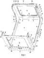
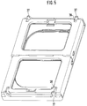
- the box shown in the figures includes two opposite longitudinal side walls 1 and 2 and two opposite narrow side walls 3 and 4 according to FIG. 1 in a rectangular plan.
- the side walls 1 to 4 are all articulated to the bottom 5 of the box, with hinges as joints or Find film hinges and the like.
- the hinged joints for the side walls 1 to 4 are preferably formed on the inner region, ie on the inner surface, as indicated schematically by 6 in FIG. 1. This means that the side walls 1 to 4 can be folded inwards towards the floor 5 in accordance with the arrow directions shown in FIG. 11.
- the joints 6 are at different levels with respect to the base 5, which is different high intermediate links 7 is reached.
- intermediate elements 7 are preferably formed in one piece with the base 5 and extend upwards on the peripheral edge of the base with respect to the base surface.
- the intermediate member 7 is the shortest and has approximately the thickness of the longitudinal side wall 1.
- the next higher intermediate member 7 is that of the longitudinal side wall 2 and subsequently that of the longitudinal side wall 4 and then 3. Accordingly, in the folded position, the longitudinal side wall 2 comes to lie on the longitudinal side wall 1, whereupon the side wall 4 and then the side wall 3 are opened.
- the gradations of the intermediate links each correspond to the thickness of the corresponding side walls, so that a perfect folding of the side walls is made possible.
- the side walls 1 and 2 are designed in the embodiment shown so that the one hand optimal display function can unfold by having a maximized opening, and on the other hand can be used as receptacles for labels, cardboard inserts and the like to be inserted. Corresponding display openings are also provided in the side walls 3 and 4, with labels and / or cardboard inserts also being attachable in these openings.
- the longitudinal side walls 1 and 2 have an appearance which is leaned onto a U-shaped frame in order to maximize a display opening, the frame being formed from two vertical web-like legs 8 and a web-like bottom bar 9 connecting the two legs 8 in the region of the floor is.
- the longitudinal side walls are involved around substantially rectangular recesses as display openings with rounded edges at 10, the different radius of curvature for these curves 10 for the long side wall 1 and the long side wall 2 only representing two different embodiments.
- the display openings 12 in the narrow side walls 3 and 4 are of rectangular cross section in the exemplary embodiment shown, vertical legs 13 also being realized here, which are connected by a strip 14 near the floor.
- the narrow side walls 3 and 4 also have a horizontal cross strut 15 forming the upper box edge, which forms a handle for the transport of the containers.
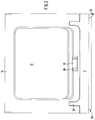
- clamping projections 17 are preferably provided in the central region of the side walls and in the bottom bar, which can be seen quite clearly from FIGS. 1, 2, 3 and 5. These clamping projections 17 have an inclined insertion ramp 18 so that the cardboard insert can be easily inserted into the groove 16. If the cardboard insert is pulled over the clamping projection 17, the cardboard insert is braced against the edges 19 of the opposite groove wall and thus held non-positively within the corresponding side wall.
- the groove depth is sufficient for a secure reception of the cardboard insert, the groove depth preferably being greater in the area of the floor strut 9 than in the vertical leg areas.
- Corresponding grooves and clamping projections are also provided in the side walls 3 and 4, here in the illustrated embodiment running all around the rectangular display opening 12.
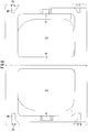
- each of the narrow side walls 3 and 4 is U-shaped in plan view, in that side wall sections extend in the manner of tongues 20 over the corner region.
- These tongue-shaped side wall sections which extend into the plane of the longitudinal side walls, overlap the legs 8 of the longitudinal side walls 1 and 2 from the outside in the upright position of the side walls.
- 8 recesses at 21 are provided in the legs, which are essentially complementary to the side wall sections 20 and accommodate these side wall sections 20 such that the outer surface of the side wall sections 20 and the outer surface 22 of the Seal longitudinal side wall 1 flush with one another, i.e. in alignment.
- the leg 8 of the side walls 1 and 2 extends to the inner surface of the side walls 4 and 3, respectively.
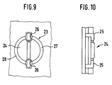
- this locking mechanism comprises a rotary knob 24 which is received in recesses 23 at the upper box edge of the side wall sections 20 and can be seen in more detail in FIG. 9 and which can be rotated in the recess 23 and cooperates with latching hooks 25 which are integrally formed on the vertical legs.
- a rotary knob 24 which is received in recesses 23 at the upper box edge of the side wall sections 20 and can be seen in more detail in FIG. 9 and which can be rotated in the recess 23 and cooperates with latching hooks 25 which are integrally formed on the vertical legs.
- latching hooks 25 which are integrally formed on the vertical legs.
- Each rotary handle 24 has ramp-like inclined surfaces 27 and 28 which extend over part of the circumference of the rotary knob and increase in thickness.
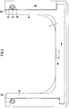
- a stacking groove 30 is formed, which is formed all the way round in the exemplary embodiment shown.
- a box of the upper stacking position with this stacked stack edge inserted from above into the box below it up to the stop surface 31, for which purpose a recess 32 in the upper box edge both in the area of the narrow side walls 1 and 2 and in the area of the legs 8 the longitudinal side walls 1 and 2 is provided.
- a tongue-shaped projection 33 remains on the outside, on which the box of the upper stack layer with the stop surface 31 rests.
- two recesses 34 are provided on the end face, which serve as stacking aids for different types of boxes, so that they have corresponding projections that are compatible with the recesses 34.
- the side walls which can be folded inwards, are designed overall so that the individual elements interlock in the folded position. So that the longitudinal side walls 1 and 2 are folded inwards and the hinges, as indicated at 6 in FIG. 1, are formed on the inner surface, after the longitudinal side walls 1 and 2 have been folded in, there is a support shoulder in the region of the floor or the intermediate links, the width of which corresponds to the thickness of the longitudinal side walls 1 and 2.
- the intermediate wall sections 20 fold into this edge-side recess which has become free after the longitudinal side walls 1 and 2 have been folded in, so that, despite these side wall sections 20, a structure of low height results when folded.
- the stops 37 In the area of the narrow side walls arranged on the floor pin-like stops 37 or support columns cooperate with corresponding recesses 38 in the narrow side walls in an upright position, the stops 37 preventing the side walls 3 and 4 from swinging outwards when erecting and overall stabilizing the box in bring the upright position with regard to a particularly shear-resistant side wall composite.
- the pin-like stops 37 which in the folded position, as shown in FIG. 8, serve slightly survive, also as stacking aids when stacking the folded boxes.
- Fig. 11 finally shows a further embodiment for the jamming of the cardboard inserts, in that two adjacent clamping projections are provided approximately in the middle of each box side wall, between which an opposite tongue 39 is present, so that the inserted cardboard insert due to the projecting into the groove 17 against the tongue 39 and is jammed against the edge regions 19.
Landscapes
- Engineering & Computer Science (AREA)
- Mechanical Engineering (AREA)
- Ceramic Engineering (AREA)
- Cartons (AREA)
- Defrosting Systems (AREA)
- Control And Other Processes For Unpacking Of Materials (AREA)
- Packging For Living Organisms, Food Or Medicinal Products That Are Sensitive To Environmental Conditiond (AREA)
Priority Applications (1)
| Application Number | Priority Date | Filing Date | Title |
|---|---|---|---|
| EP97120567A EP0835816A3 (fr) | 1994-10-07 | 1995-08-09 | Récipient en forme de caisse |
Applications Claiming Priority (4)
| Application Number | Priority Date | Filing Date | Title |
|---|---|---|---|
| CH3023/94 | 1994-10-07 | ||
| CH302394 | 1994-10-07 | ||
| DE4446322A DE4446322A1 (de) | 1994-10-07 | 1994-12-23 | Kastenförmiger Behälter |
| DE4446322 | 1994-12-23 |
Related Child Applications (1)
| Application Number | Title | Priority Date | Filing Date |
|---|---|---|---|
| EP97120567A Division EP0835816A3 (fr) | 1994-10-07 | 1995-08-09 | Récipient en forme de caisse |
Publications (3)
| Publication Number | Publication Date |
|---|---|
| EP0705764A2 true EP0705764A2 (fr) | 1996-04-10 |
| EP0705764A3 EP0705764A3 (fr) | 1996-07-31 |
| EP0705764B1 EP0705764B1 (fr) | 1999-02-10 |
Family
ID=25691965
Family Applications (1)
| Application Number | Title | Priority Date | Filing Date |
|---|---|---|---|
| EP95112558A Expired - Lifetime EP0705764B1 (fr) | 1994-10-07 | 1995-08-09 | Récipient en forme de caisse |
Country Status (3)
| Country | Link |
|---|---|
| EP (1) | EP0705764B1 (fr) |
| AT (1) | ATE176647T1 (fr) |
| DK (1) | DK0705764T3 (fr) |
Cited By (9)
| Publication number | Priority date | Publication date | Assignee | Title |
|---|---|---|---|---|
| EP0786412A1 (fr) * | 1996-01-26 | 1997-07-30 | bekuplast Kunststoffverarbeitungs-GmbH | Récipient de stockage ou de transport |
| WO1998056668A1 (fr) * | 1997-06-11 | 1998-12-17 | Mckechnie Uk Limited | Contenant empilable et emboitable |
| US6863180B2 (en) | 2002-02-15 | 2005-03-08 | Rehrig Pacific Company | Collapsible container |
| US7017766B2 (en) | 2003-03-10 | 2006-03-28 | Rehrig Pacific Company | Collapsible container with side wall latching capability |
| US7048134B1 (en) | 2000-07-18 | 2006-05-23 | Rehrig Pacific Company | Container |
| US7059489B2 (en) | 2002-10-11 | 2006-06-13 | Rehrig Pacific Company | Portable storage device |
| US7104414B2 (en) | 2002-01-12 | 2006-09-12 | Rehrig Pacific Company | Collapsible container |
| US7195127B2 (en) | 2003-05-13 | 2007-03-27 | Rehrig Pacific Company | Collapsible container |
| US10167110B2 (en) | 2010-05-27 | 2019-01-01 | Rehrig Pacific Company | Dual height collapsible container |
Families Citing this family (2)
| Publication number | Priority date | Publication date | Assignee | Title |
|---|---|---|---|---|
| US7357269B2 (en) | 2005-11-01 | 2008-04-15 | Rehrig Pacific Company | Container |
| US7717283B2 (en) | 2007-11-06 | 2010-05-18 | Rehrig Pacific Company | Collapsible container |
Family Cites Families (12)
| Publication number | Priority date | Publication date | Assignee | Title |
|---|---|---|---|---|
| FR1592818A (fr) * | 1968-11-22 | 1970-05-19 | ||
| BE754181A (fr) * | 1969-08-06 | 1970-12-31 | Krauss Maffei Ag | Dispositif de verrouillage pour container |
| NL154463B (nl) * | 1971-01-07 | 1977-09-15 | Wiva Nv | Vierwandige bak. |
| US3889837A (en) * | 1974-01-24 | 1975-06-17 | Pretty Products Inc | Dish drainer having integrally hinged sidewalls |
| FR2268700A1 (en) * | 1974-04-26 | 1975-11-21 | Bardy Jean | Re-usable moulded plastic vegetable tray - has sides attached to base by thin hinge pieces so tray can be returned flat |
| CA1225941A (fr) * | 1985-01-22 | 1987-08-25 | Larry R. Hughes | Contenant d'expedition pliant |
| NL8802952A (nl) * | 1988-11-30 | 1990-06-18 | Dynoplast Bv | Stapelbare bak. |
| US4917255A (en) * | 1989-02-24 | 1990-04-17 | J.I.T. Corporation | Collapsible container |
| DE4002467C1 (en) * | 1990-01-29 | 1991-05-29 | Kay Uwe 4005 Meerbusch De Kaul | Connector for display frames - has abutments on members to engage behind guide faces on connector |
| GB9302293D0 (en) * | 1993-02-05 | 1993-03-24 | Quotatech Ltd | Packing system for goods |
| US5285900A (en) * | 1993-04-15 | 1994-02-15 | Swingler Sheni S | Stackable storage containers |
| DE9314569U1 (de) * | 1993-09-27 | 1994-02-24 | Schneider Ekkehard Dipl Ing | Lager- und Transportbehälter mit Deckel und einer lösbaren Seitenwand |
-
1995
- 1995-08-09 AT AT95112558T patent/ATE176647T1/de not_active IP Right Cessation
- 1995-08-09 DK DK95112558T patent/DK0705764T3/da active
- 1995-08-09 EP EP95112558A patent/EP0705764B1/fr not_active Expired - Lifetime
Non-Patent Citations (1)
| Title |
|---|
| None |
Cited By (13)
| Publication number | Priority date | Publication date | Assignee | Title |
|---|---|---|---|---|
| WO1997027115A1 (fr) * | 1996-01-26 | 1997-07-31 | Bekuplast Kunststoffverarbeitungs-Gmbh | Recipient de transport et de stockage |
| EP0786412A1 (fr) * | 1996-01-26 | 1997-07-30 | bekuplast Kunststoffverarbeitungs-GmbH | Récipient de stockage ou de transport |
| WO1998056668A1 (fr) * | 1997-06-11 | 1998-12-17 | Mckechnie Uk Limited | Contenant empilable et emboitable |
| GB2340482A (en) * | 1997-06-11 | 2000-02-23 | Mckechnie Uk Ltd | Stackable and nestable container |
| GB2340482B (en) * | 1997-06-11 | 2001-06-06 | Mckechnie Uk Ltd | Container |
| EP1241105A1 (fr) * | 1997-06-11 | 2002-09-18 | C.G. Paxton Limited | Conteneur pliable |
| US7048134B1 (en) | 2000-07-18 | 2006-05-23 | Rehrig Pacific Company | Container |
| US7104414B2 (en) | 2002-01-12 | 2006-09-12 | Rehrig Pacific Company | Collapsible container |
| US6863180B2 (en) | 2002-02-15 | 2005-03-08 | Rehrig Pacific Company | Collapsible container |
| US7059489B2 (en) | 2002-10-11 | 2006-06-13 | Rehrig Pacific Company | Portable storage device |
| US7017766B2 (en) | 2003-03-10 | 2006-03-28 | Rehrig Pacific Company | Collapsible container with side wall latching capability |
| US7195127B2 (en) | 2003-05-13 | 2007-03-27 | Rehrig Pacific Company | Collapsible container |
| US10167110B2 (en) | 2010-05-27 | 2019-01-01 | Rehrig Pacific Company | Dual height collapsible container |
Also Published As
| Publication number | Publication date |
|---|---|
| EP0705764B1 (fr) | 1999-02-10 |
| ATE176647T1 (de) | 1999-02-15 |
| DK0705764T3 (da) | 1999-09-20 |
| EP0705764A3 (fr) | 1996-07-31 |
Similar Documents
| Publication | Publication Date | Title |
|---|---|---|
| DE60105000T2 (de) | Klappbodenbehälter | |
| DE3347367C2 (fr) | ||
| EP2477902A1 (fr) | Caisse utilisable de manière flexible | |
| DE2643720C2 (de) | Stapelbarer Transportbehälter | |
| EP0705764B1 (fr) | Récipient en forme de caisse | |
| EP0508240A2 (fr) | Conteneur réutilisable | |
| EP0835816A2 (fr) | Récipient en forme de caisse | |
| DE4143023C1 (en) | Folding frame for box on pallet - has geometric folding axes of each frame wall offset to assist folding procedure | |
| EP0507909B1 (fr) | Systeme de conteneurs, en particulier systeme de conteneurs de transport et/ou d'emballage | |
| EP0524658A1 (fr) | Palette en matière plastique | |
| EP0860366A1 (fr) | Conteneur pliable | |
| DE2525169B2 (de) | Kunststoff-flaschenkasten mit verriegelungsvorrichtung | |
| EP0440844B1 (fr) | Caisses avec des moyens pour relier les unes aux autres des caisses par liaison momentanée | |
| DE4330627A1 (de) | Verpackungsbehälter | |
| DE1221958B (de) | Zusammenlegbare Kiste | |
| DE4230027A1 (de) | Mehrweg-Transportbehälter | |
| EP0698558A2 (fr) | Récipient de transport empilable | |
| EP0699160B1 (fr) | Contenants empilables et emboitables | |
| DE3922635C2 (fr) | ||
| DE2405875A1 (de) | Auseinandernehmbarer kasten aus kunststoff | |
| DE3602632A1 (de) | Verriegelung zweier aneinandergrenzender kunststoffteile von geringer wandstaerke | |
| WO1994005554A1 (fr) | Recipient de transport reutilisable | |
| DE4228370A1 (de) | Tragbarer transport- und aufbewahrungsbehaelter | |
| AT522769B1 (de) | Faltkiste | |
| DE4126749A1 (de) | Behaelter aus kunststoff zur aufnahme von gegenstaenden |
Legal Events
| Date | Code | Title | Description |
|---|---|---|---|
| PUAI | Public reference made under article 153(3) epc to a published international application that has entered the european phase |
Free format text: ORIGINAL CODE: 0009012 |
|
| AK | Designated contracting states |
Kind code of ref document: A2 Designated state(s): AT BE CH DE DK ES FR IT LI NL |
|
| PUAL | Search report despatched |
Free format text: ORIGINAL CODE: 0009013 |
|
| 17P | Request for examination filed |
Effective date: 19960523 |
|
| AK | Designated contracting states |
Kind code of ref document: A3 Designated state(s): AT BE CH DE DK ES FR IT LI NL |
|
| 17Q | First examination report despatched |
Effective date: 19970523 |
|
| GRAG | Despatch of communication of intention to grant |
Free format text: ORIGINAL CODE: EPIDOS AGRA |
|
| GRAG | Despatch of communication of intention to grant |
Free format text: ORIGINAL CODE: EPIDOS AGRA |
|
| GRAG | Despatch of communication of intention to grant |
Free format text: ORIGINAL CODE: EPIDOS AGRA |
|
| GRAH | Despatch of communication of intention to grant a patent |
Free format text: ORIGINAL CODE: EPIDOS IGRA |
|
| GRAH | Despatch of communication of intention to grant a patent |
Free format text: ORIGINAL CODE: EPIDOS IGRA |
|
| GRAA | (expected) grant |
Free format text: ORIGINAL CODE: 0009210 |
|
| RAP1 | Party data changed (applicant data changed or rights of an application transferred) |
Owner name: SCHOELLER PLAST SA |
|
| AK | Designated contracting states |
Kind code of ref document: B1 Designated state(s): AT BE CH DE DK ES FR IT LI NL |
|
| PG25 | Lapsed in a contracting state [announced via postgrant information from national office to epo] |
Ref country code: IT Free format text: LAPSE BECAUSE OF FAILURE TO SUBMIT A TRANSLATION OF THE DESCRIPTION OR TO PAY THE FEE WITHIN THE PRESCRIBED TIME-LIMIT;WARNING: LAPSES OF ITALIAN PATENTS WITH EFFECTIVE DATE BEFORE 2007 MAY HAVE OCCURRED AT ANY TIME BEFORE 2007. THE CORRECT EFFECTIVE DATE MAY BE DIFFERENT FROM THE ONE RECORDED. Effective date: 19990210 Ref country code: ES Free format text: THE PATENT HAS BEEN ANNULLED BY A DECISION OF A NATIONAL AUTHORITY Effective date: 19990210 |
|
| REF | Corresponds to: |
Ref document number: 176647 Country of ref document: AT Date of ref document: 19990215 Kind code of ref document: T |
|
| REG | Reference to a national code |
Ref country code: CH Ref legal event code: NV Representative=s name: R. A. EGLI & CO. PATENTANWAELTE Ref country code: CH Ref legal event code: EP |
|
| ET | Fr: translation filed | ||
| REF | Corresponds to: |
Ref document number: 59505078 Country of ref document: DE Date of ref document: 19990325 |
|
| PG25 | Lapsed in a contracting state [announced via postgrant information from national office to epo] |
Ref country code: AT Free format text: LAPSE BECAUSE OF NON-PAYMENT OF DUE FEES Effective date: 19990809 |
|
| PG25 | Lapsed in a contracting state [announced via postgrant information from national office to epo] |
Ref country code: DK Free format text: LAPSE BECAUSE OF NON-PAYMENT OF DUE FEES Effective date: 19990831 Ref country code: BE Free format text: LAPSE BECAUSE OF NON-PAYMENT OF DUE FEES Effective date: 19990831 |
|
| REG | Reference to a national code |
Ref country code: DK Ref legal event code: T3 |
|
| PLBE | No opposition filed within time limit |
Free format text: ORIGINAL CODE: 0009261 |
|
| STAA | Information on the status of an ep patent application or granted ep patent |
Free format text: STATUS: NO OPPOSITION FILED WITHIN TIME LIMIT |
|
| 26N | No opposition filed | ||
| BERE | Be: lapsed |
Owner name: S.A. SCHOELLER PLAST Effective date: 19990831 |
|
| PG25 | Lapsed in a contracting state [announced via postgrant information from national office to epo] |
Ref country code: NL Free format text: LAPSE BECAUSE OF NON-PAYMENT OF DUE FEES Effective date: 20000301 |
|
| PG25 | Lapsed in a contracting state [announced via postgrant information from national office to epo] |
Ref country code: FR Free format text: LAPSE BECAUSE OF NON-PAYMENT OF DUE FEES Effective date: 20000428 |
|
| REG | Reference to a national code |
Ref country code: DK Ref legal event code: EBP |
|
| NLV4 | Nl: lapsed or anulled due to non-payment of the annual fee |
Effective date: 20000301 |
|
| PG25 | Lapsed in a contracting state [announced via postgrant information from national office to epo] |
Ref country code: DE Free format text: LAPSE BECAUSE OF NON-PAYMENT OF DUE FEES Effective date: 20000601 |
|
| REG | Reference to a national code |
Ref country code: FR Ref legal event code: ST |
|
| PGFP | Annual fee paid to national office [announced via postgrant information from national office to epo] |
Ref country code: CH Payment date: 20010824 Year of fee payment: 7 |
|
| PG25 | Lapsed in a contracting state [announced via postgrant information from national office to epo] |
Ref country code: LI Free format text: LAPSE BECAUSE OF NON-PAYMENT OF DUE FEES Effective date: 20020831 Ref country code: CH Free format text: LAPSE BECAUSE OF NON-PAYMENT OF DUE FEES Effective date: 20020831 |
|
| REG | Reference to a national code |
Ref country code: CH Ref legal event code: PL |