EP0705730B1 - Headlight with dipped and distance light for vehicle - Google Patents
Headlight with dipped and distance light for vehicle Download PDFInfo
- Publication number
- EP0705730B1 EP0705730B1 EP95114689A EP95114689A EP0705730B1 EP 0705730 B1 EP0705730 B1 EP 0705730B1 EP 95114689 A EP95114689 A EP 95114689A EP 95114689 A EP95114689 A EP 95114689A EP 0705730 B1 EP0705730 B1 EP 0705730B1
- Authority
- EP
- European Patent Office
- Prior art keywords
- light source
- reflector
- headlight according
- headlight
- cap
- Prior art date
- Legal status (The legal status is an assumption and is not a legal conclusion. Google has not performed a legal analysis and makes no representation as to the accuracy of the status listed.)
- Expired - Lifetime
Links
Images


Classifications
-
- B—PERFORMING OPERATIONS; TRANSPORTING
- B60—VEHICLES IN GENERAL
- B60Q—ARRANGEMENT OF SIGNALLING OR LIGHTING DEVICES, THE MOUNTING OR SUPPORTING THEREOF OR CIRCUITS THEREFOR, FOR VEHICLES IN GENERAL
- B60Q1/00—Arrangement of optical signalling or lighting devices, the mounting or supporting thereof or circuits therefor
- B60Q1/02—Arrangement of optical signalling or lighting devices, the mounting or supporting thereof or circuits therefor the devices being primarily intended to illuminate the way ahead or to illuminate other areas of way or environments
- B60Q1/04—Arrangement of optical signalling or lighting devices, the mounting or supporting thereof or circuits therefor the devices being primarily intended to illuminate the way ahead or to illuminate other areas of way or environments the devices being headlights
- B60Q1/14—Arrangement of optical signalling or lighting devices, the mounting or supporting thereof or circuits therefor the devices being primarily intended to illuminate the way ahead or to illuminate other areas of way or environments the devices being headlights having dimming means
- B60Q1/1415—Dimming circuits
-
- F—MECHANICAL ENGINEERING; LIGHTING; HEATING; WEAPONS; BLASTING
- F21—LIGHTING
- F21S—NON-PORTABLE LIGHTING DEVICES; SYSTEMS THEREOF; VEHICLE LIGHTING DEVICES SPECIALLY ADAPTED FOR VEHICLE EXTERIORS
- F21S41/00—Illuminating devices specially adapted for vehicle exteriors, e.g. headlamps
- F21S41/60—Illuminating devices specially adapted for vehicle exteriors, e.g. headlamps characterised by a variable light distribution
- F21S41/65—Illuminating devices specially adapted for vehicle exteriors, e.g. headlamps characterised by a variable light distribution by acting on light sources
- F21S41/657—Illuminating devices specially adapted for vehicle exteriors, e.g. headlamps characterised by a variable light distribution by acting on light sources by moving light sources
-
- F—MECHANICAL ENGINEERING; LIGHTING; HEATING; WEAPONS; BLASTING
- F21—LIGHTING
- F21S—NON-PORTABLE LIGHTING DEVICES; SYSTEMS THEREOF; VEHICLE LIGHTING DEVICES SPECIALLY ADAPTED FOR VEHICLE EXTERIORS
- F21S41/00—Illuminating devices specially adapted for vehicle exteriors, e.g. headlamps
- F21S41/60—Illuminating devices specially adapted for vehicle exteriors, e.g. headlamps characterised by a variable light distribution
- F21S41/68—Illuminating devices specially adapted for vehicle exteriors, e.g. headlamps characterised by a variable light distribution by acting on screens
- F21S41/683—Illuminating devices specially adapted for vehicle exteriors, e.g. headlamps characterised by a variable light distribution by acting on screens by moving screens
- F21S41/692—Shields, i.e. screens not creating an image meant to be projected
-
- F—MECHANICAL ENGINEERING; LIGHTING; HEATING; WEAPONS; BLASTING
- F21—LIGHTING
- F21S—NON-PORTABLE LIGHTING DEVICES; SYSTEMS THEREOF; VEHICLE LIGHTING DEVICES SPECIALLY ADAPTED FOR VEHICLE EXTERIORS
- F21S41/00—Illuminating devices specially adapted for vehicle exteriors, e.g. headlamps
- F21S41/10—Illuminating devices specially adapted for vehicle exteriors, e.g. headlamps characterised by the light source
- F21S41/14—Illuminating devices specially adapted for vehicle exteriors, e.g. headlamps characterised by the light source characterised by the type of light source
- F21S41/17—Discharge light sources
Landscapes
- Engineering & Computer Science (AREA)
- General Engineering & Computer Science (AREA)
- Mechanical Engineering (AREA)
- Non-Portable Lighting Devices Or Systems Thereof (AREA)
- Lighting Device Outwards From Vehicle And Optical Signal (AREA)
Description
Die Erfindung geht aus von einem Scheinwerfer für Abblendlicht und Fernlicht für Fahrzeuge nach der Gattung des Anspruchs 1.The invention is based on a headlight for low beam and high beam for vehicles according to the preamble of claim 1.
Ein solcher Scheinwerfer ist durch die EP-A-0595267 bekannt. Dieser Scheinwerfer weist einen Reflektor und eine Lichtquelle in Form einer Gasentladungslampe auf. Die Lichtquelle ist durch ein Stellelement zwischen einer Stellung für Abblendlicht und einer Stellung für Fernlicht in Richtung der optischen Achse des Reflektors und zusätzlich auch vertikal zur optischen Achse bewegbar. Beim Scheinwerfer gemäß diesem Dokument soll die Helldunkelgrenze dadurch erzeugt werden, daß durch den Reflektor von der Lichtquelle ausgesandtes Licht als ein Lichtbündel reflektiert wird, das durch die Form des Reflektors die Helldunkelgrenze aufweist. Bei Verwendung einer Gasentladungslampe als Lichtquelle, die gegenüber einer Glühlampe einen wesentlich höheren Lichtstrom aussendet, muß bei der Erzeugung des Abblendlichts besonders darauf geachtet werden, daß keine Blendung des Gegenverkehrs verursacht wird, wozu das Abblendlicht eine exakt eingestellte und deutlich ausgeprägte Helldunkelgenze aufweisen muß. Bei Verwendung einer Gasentladungslampe ist es wegen der zum Teil diffusen Lichtabgabe durch diese schwierig, eine exakt eingestellte und deutlich ausgeprägte Helldunkelgrenze des Abblendlichts zu erreichen.Such a headlight is known from EP-A-0595267. This headlight has a reflector and a light source in the form of a gas discharge lamp. The light source is through an actuator between a position for low beam and a position for high beam in the direction of the optical axis of the Reflector and also vertical to the optical axis movable. In the headlamp according to this document, the The light-dark boundary can be generated by the reflector light emitted by the light source as a bundle of light is reflected, the light-dark boundary by the shape of the reflector having. When using a gas discharge lamp as a light source that is essential compared to an incandescent lamp emits higher luminous flux when generating the low beam special care should be taken to ensure that there is no glare from the Oncoming traffic is caused, for which the low beam is an exact have set and clearly pronounced chiaroscuro got to. When using a gas discharge lamp, it is because of the Partially diffuse light emission due to this difficult, an exact set and clearly defined light / dark limit of the Low beam to reach.
Durch die EP-A-0220068 ist ein Scheinwerfer für Abblendlicht und Fernlicht für Fahrzeuge bekannt, der einen Reflektor und eine Lichtquelle in Form einer Gasentladungslampe aufweist, wobei der Reflektor zusammen mit der Lichtquelle bewegbar ist. Wie die Helldunkelgrenze des Abblendlichts erzeugt wird ist in diesem Dokument nicht angegeben.By EP-A-0220068 is a headlight for low beam and High beam known for vehicles, the one reflector and one Has light source in the form of a gas discharge lamp, the Reflector can be moved together with the light source. As the Low-light limit of the low beam is generated in this Document not specified.
Der erfindungsgemäße Scheinwerfer mit den Merkmalen gemäß Anspruch 1 hat demgegenüber den Vorteil, daß durch die Abschirmvorrichtung sichergestellt ist, daß die Helldunkelgrenze des Abblendlichts die erforderliche Lage einnimmt und deutlich ausgeprägt ist, so daß sichergestellt ist, daß keine Blendung des Gegenverkehrs auftritt.The headlight according to the invention with the features according to Claim 1 has the advantage that the Shielding device ensures that the light-dark boundary of the low beam takes the required position and clearly is pronounced so that it is ensured that there is no glare oncoming traffic occurs.
In den abhängigen Ansprüchen sind vorteilhafte Ausgestaltungen und Weiterbildungen des erfindungsgemäßen Scheinwerfers angegeben. Advantageous embodiments are in the dependent claims and developments of the headlamp according to the invention specified.
Eine einfache Bildung der Abschirmvorrichtung
ist durch die Ausbildung gemäß Anspruch 2 erreicht.
Durch die Ausbildung gemäß Anspruch 8 ist sichergestellt,
daß sich die Lichtquelle in exakt festgelegten Stellungen
für die Erzeugung des Abblendlichts und/oder des
Fernlichts befindet. Das elastisch verformbare Zwischenglied
gemäß Anspruch 9 stellt einerseits unabhängig von Fertigungstoleranzen
die Anlage an den Anschlägen sicher und gewährleistet
außerdem die Anlage an den Anschlägen auch bei
eventuell auftretenden Erschütterungen. In den Ansprüchen 12
und 16 sind einfach aufgebaute und nur kleine Verstellwege
zwischen den Stellungen für Abblendlicht und Fernlicht erfordernde
Abschirmvorrichtungen angegeben.A simple formation of the shielding device
is achieved by the training according to claim 2.
The training according to claim 8 ensures
that the light source is in precisely defined positions
for the generation of the low beam and / or the
High beam. The elastically deformable intermediate link
according to claim 9, on the one hand, is independent of manufacturing tolerances
the system at the stops safe and guaranteed
also the attachment to the attacks
possible vibrations. In
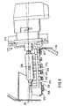
Mehrere Ausführungsbeispiele der Erfindung sind in der Zeichnung dargestellt und in der nachfolgenden Beschreibung näher erläutert. Es zeigen Figur 1 einen Scheinwerfer für Abblendlicht und Fernlicht für Fahrzeuge in einem vertikalen Längsschnitt mit einem Stellelement zur Bewegung der Lichtquelle nach einem ersten Ausführungsbeispiel, Figur 2 einen vor dem Scheinwerfer angeordneten Meßschirm, der durch das vom Reflektor in der Betriebsstellung Abblendlicht ausgesandte Lichtbündel beleuchtet wird, Figur 3 den Meßschirm bei der Beleuchtung durch das vom Reflektor in der Betriebsstellung Fernlicht ausgesandte Lichtbündel, Figur 4 den Meßschirm bei der Beleuchtung durch das aus dem Scheinwerfer nach Durchtritt durch eine Streuscheibe austretende Lichtbündel in der Betriebsstellung Abblendlicht, Figur 5 den Meßschirm bei der Beleuchtung durch das aus dem Scheinwerfer nach Durchtritt durch die Streuscheibe austretende Lichtbündel in der Betriebsstellung Fernlicht, Figur 6 einen Ausschnitt des Scheinwerfers mit einer Variante des Stellelements zur Bewegung der Lichtquelle und Figur 7 einen Ausschnitt des Scheinwerfers mit einem zweiten Ausführungsbeispiel des Stellelements zur Bewegung der Lichtquelle, Figur 8 einen Ausschnitt des Scheinwerfers gemäß einem dritten Ausführungsbeispiel mit einer modifizierten Abschirmvorrichtung in einer Stellung für Abblendlicht, Figur 9 den Scheinwerfer von Figur 8 mit der Abschirmvorrichtung in einer Stellung für Fernlicht, Figur 10 einen Ausschnitt des Scheinwerfers gemäß einem vierten Ausführungsbeispiel mit einer modifizierten Abschirmvorrichtung in einer Stellung für Abblendlicht in der Ansicht entgegen Lichtaustrittsrichtung und Figur 11 den Scheinwerfer von Figur 10 mit der Abschirmvorrichtung in einer Stellung für Fernlicht.Several embodiments of the invention are in the Drawing shown and in the description below explained in more detail. FIG. 1 shows a headlight for Low beam and high beam for vehicles in a vertical Longitudinal section with an actuator for moving the light source according to a first embodiment, Figure 2 a in front of the headlight arranged measuring screen, which by the Low beam emitted by the reflector in the operating position 3 is the measuring screen when lighting by the reflector in the operating position Beam emitted light beam, Figure 4 the measuring screen when lighting through that from the headlight bundles of light emerging after passing through a diffusing screen in the low beam operating position, FIG Measuring screen for the lighting from the headlights bundles of light emerging after passing through the lens in the high beam operating position, FIG. 6 shows a detail of the headlamp with a variant of the control element for moving the light source and Figure 7 shows a section of the headlight with a second embodiment of the actuator for moving the light source, figure 8 shows a detail of the headlight according to a third Embodiment with a modified shielding device in a position for low beam, Figure 9 the headlight of Figure 8 with the shielding device in one Position for high beam, Figure 10 shows a section of the Headlamp according to a fourth embodiment a modified shielding device in one position for low beam in the view opposite the light exit direction and FIG. 11 the headlight from FIG. 10 with the shielding device in a high beam position.
Ein in Figur 1 dargestellter Scheinwerfer für Abblendlicht
und Fernlicht für Fahrzeuge, insbesondere Kraftfahrzeuge,
weist einen Reflektor 10 und eine Lichtquelle 12 auf. Der
Reflektor 10 ist in einer Halterung oder einem Gehäuse 14
verstellbar angeordnet. Die Lichtaustrittsöffnung des Gehäuses
14 ist mit einer lichtdurchlässigen Scheibe 16 aus
Kunststoff oder Glas abgedeckt, die als glatte Scheibe ausgebildet
sein kann oder optisch wirksame Elemente aufweisen
kann, durch die das hindurchtretende Licht abgelenkt wird.
Der Reflektor 10 kann aus Kunststoff oder Metall bestehen
und weist in seinem Scheitelbereich eine Öffnung 18 auf,
durch die die Lichtquelle 12 von der Rückseite her in den
Reflektor 10 hineinragt. Die Lichtquelle 12
ist eine Gasentladungslampe und weist einen
Leuchtkörper 20 auf, der
der Lichtbogen ist und der von einer zumindest bereichsweise
lichtdurchlässigen Umhüllung 21 aus Glas umschlossen ist.A headlight for low beam shown in Figure 1
and high beam for vehicles, especially motor vehicles,
has a
Die Lichtquelle 12 ist in einem Lampenträger 22 eingesetzt,
der einen dem Sockel 13 der Lichtquelle 12 angepaßten Aufnahmeabschnitt
24 aufweist und der von der Rückseite des Reflektors
10 her an die Öffnung 18 angesetzt ist. Der Lampenträger
22 kann aus Metall, Kunststoff oder Keramik bestehen.
Die Lichtquelle 12 ist in bekannter Weise mittels eines am
Lampenträger 22 angeordneten elastischen Befestigungselements
26 im Lampenträger 22 gehalten, das beispielsweise als
ein Befestigungsbügel aus Draht ausgebildet sein kann. Auf
der Rückseite des Reflektors 10 sind oberhalb von dessen
Öffnung 18 mit horizontalem Abstand zueinander zwei Träger
26 angeordnet, von denen in Figur 1 nur einer erkennbar ist,
die einstückig mit dem Reflektor 10 ausgebildet sein können
oder als separate Teile am Reflektor 10 befestigt sein können.
Der Lampenträger 22 ist in seinem oberen Randbereich an
den Trägern 26 um eine sich horizontal und senkrecht zur optischen
Achse 11 des Reflektors 10 erstreckende Achse 30
schwenkbar gelagert. An seinem der Schwenkachse 30 gegenüberliegenden
unteren Randbereich weist der Lampenträger 22
eine Nase 32 auf. Auf der Rückseite des Reflektors 10 ist
unterhalb der Öffnung 18 eine Konsole 34 angeordnet, die
einstückig mit dem Reflektor 10 ausgebildet ist, jedoch auch
als separates Teil am Reflektor 10 befestigt sein kann. Die
Konsole 34 weist eine in Richtung der optischen Achse 11 des
Reflektors 10 langgestreckte Ausnehmung 36 auf, in die die
Nase 32 des Lampenträgers 22 eingreift und in der Ausnehmung
36 entlang deren Längserstreckung bewegbar ist. Die Ausnehmung
36 weist zum Reflektor 10 hin einen vorderen Rand 37
und vom Reflektor 10 weg einen hinteren Rand 38 auf. An der
Nase 32 des Lampenträgers 22 ist ein elastisch verformbares
Zwischenglied 40 befestigt, das beispielsweise als eine
Blattfeder ausgebildet sein kann, die in einem Schlitz 42 in
der Nase 32 befestigt ist. Am freien Ende des Zwischenglieds
40 greift ein Stellelement 42 an, das nachfolgend noch näher
beschrieben wird und durch das eine Schwenkbewegung des Lampenträgers
22 um die Achse 30 bewirkt werden kann. The
Die Umhüllung 21 der Lichtquelle 12 ist etwa rohrförmig ausgebildet
und auf dieser sind seitlich sich etwa parallel zur
optischen Achse 11 des Reflektors 10 erstreckende Streifen
44 aus einer lichtundurchlässigen Beschichtung angeordnet.
Der zwischen den Streifen 44 angeordnete obere und untere
Umfangsbereich der Umhüllung 21 ist nicht von der Beschichtung
bedeckt und lichtdurchlässig. Zusätzlich zu den Streifen
44 kann auch das in Lichtaustrittsrichtung 46 weisende
Stirnende der Umhüllung 21 von der Beschichtung bedeckt
sein, um zu verhindern, daß vom Leuchtkörper 20 ausgesandtes
Licht direkt, das heißt ohne Reflexion am Reflektor 10 austritt.
Unterhalb der Lichtquelle 12 ist im Reflektor 10 eine
lichtundurchlässige Kappe 48 angeordnet, durch die vom
Leuchtkörper 20 der Lichtquelle 12 ausgesandtes, durch den
zwischen den Streifen 44 angeordneten unteren Umfangsbereich
der Umhüllung 21 austretendes Licht abgeschirmt wird, so daß
es nicht auf den Reflektor 10 treffen kann. Die Kappe 48
bildet zusammen mit den Streifen 44 auf der Umhüllung 21 eine
Abschirmvorrichtung, durch die ein Teil des vom Leuchtkörper
20 der Lichtquelle 12 ausgesandten Lichts abgeschirmt
wird. Durch die oberen Ränder der Streifen 44 wird eine
obere Helldunkelgrenze des aus dem Scheinwerfer austretenden
Lichtbündels gebildet. Die Kappe 48 ist starr mit dem Lampenträger
22 verbunden, kann jedoch auch einstückig mit diesem
ausgebildet sein, so daß sie die durch das Stellelement
42 bewirkte Bewegung des Lampenträgers 22 und der in diesem
angeordneten Lichtquelle 12 ebenfalls ausführt. Die Umhüllung
21 der Lichtquelle 12 kann auch über ihren gesamten Umfang
lichtdurchlässig ausgebildet sein, wobei dann die Kappe
48 so ausgebildet ist, daß durch deren obere Ränder die
Helldunkelgrenze des vom Reflektor 10 reflektierten Abblendlichtbündels
gebildet wird. The
In einer Stellung des Lampenträgers 22 und der in diesem angeordneten
Lichtquelle 12 mit deren Leuchtkörper 20 für Abblendlicht,
wie sie in Figur 1 mit durchgezogenen Linien
dargestellt ist, befindet sich die Nase 32 des Lampenträgers
22 durch das Stellelement 42 bewirkt in der Anlage am vorderen
Rand 37 der Ausnehmung. Der Leuchtkörper 20 der Lichtquelle
12 befindet sich dabei in einer genau festgelegten
Stellung bezüglich dem Reflektor 10, so daß das vom Leuchtkörper
20 ausgesandte Licht vom Reflektor 10 zur Bildung eines
Abblendlichtbündels reflektiert wird. Durch die Streifen
44 wird dabei die Helldunkelgrenze des Abblendlichtbündels
erzeugt.In a position of the
In den Figuren 2 bis 5 ist ein vor dem Scheinwerfer angeordneter
Meßschirm 50 dargestellt, der die Projektion einer vor
dem Scheinwerfer angeordneten Fahrbahn darstellt, die beim
realen Einsatz des Scheinwerfers entsprechend beleuchtet
würde. Der Meßschirm 50 weist eine horizontale Mittelebene
HH und eine vertikale Mittelebene VV auf. In Figur 2 ist der
Meßschirm 50 bei der Beleuchtung durch das vom Reflektor 10
bei in ihrer Abblendlichtstellung angeordneter Lichtquelle
12 reflektierte Lichtbündel ohne den Einfluß optisch wirksamer
Elemente der Abdeckscheibe 16 dargestellt. Dieses Lichtbündel
beleuchtet den Meßschirm 50 in einem Bereich, der
nach oben durch die Helldunkelgrenze 54,55 begrenzt ist. Die
Helldunkelgrenze weist auf der linken Seite des Meßschirms
50, das heißt auf der Gegenverkehrsseite bei Rechtsverkehr,
einen horizontalen Abschnitt 54 und auf der rechten Seite
des Meßschirms 50, das heißt auf der eigenen Verkehrsseite
bei Rechtsverkehr, einen zum äußeren Rand hin ansteigenden
Abschnitt 55. Die direkt unterhalb der Helldunkelgrenze 54
und 55 beleuchteten Bereiche sind mit 56 und 57 bezeichnet
und ein Bereich weiter unterhalb der Helldunkelgrenze 54,55
nahe der vertikalen Mittelebene VV des Meßschirms ist mit 58
bezeichnet. In Figur 4 ist der Meßschirm 50 bei der Beleuchtung
durch das aus dem Scheinwerfer austretende Abblendlichtbündel
nach Durchtritt durch die Abdeckscheibe 16 und
Ablenkung durch optisch wirksame Elemente der Abdeckscheibe
16 dargestellt. Durch die optisch wirksamen Elemente wird
eine Streuung des Lichtbündels bewirkt, wobei der Bereich
56' entlang dem horizontalen Abschnitt 54 der Helldunkelgrenze
gestreut ist, der Bereich 57' entlang dem ansteigenden
Abschnitt 55 der Helldunkelgrenze gestreut ist und der
Bereich 58' im wesentlichen in horizontaler Richtung gestreut
ist.In FIGS. 2 to 5, one is arranged in front of the headlight
Measuring
In Figur 1 ist der Lampenträger 22 zusammen mit der in diesem
angeordneten Lichtquelle 12 und deren Leuchtkörper 20
mit gestrichelten Linien in der Stellung für Fernlicht dargestellt.
In dieser Fernlichtstellung befindet sich die Nase
32 des Lampenträgers 22 durch das Stellelement 42 bewirkt in
der Anlage am hinteren Rand 38 der Ausnehmung. Der Leuchtkörper
20 der Lichtquelle 12 ist gegenüber der Stellung für
Abblendlicht in Richtung der optischen Achse 11 näher zum
Reflektorscheitel hin angeordnet und außerdem vertikal bezüglich
der optischen Achse 11 nach unten versetzt. Die
Kappe 48 ist in ihrer Fernlichtstellung gegenüber ihrer Abblendlichtstellung
ebenfalls in Richtung der optischen Achse
11 näher zum Reflektorscheitel hin und außerdem bezüglich
der optischen Achse 11 nach unten versetzt angeordnet. In
Figur 3 ist der Meßschirm 50 bei Beleuchtung durch das vom
Reflektor 10 bei in ihrer Fernlichtstellung angeordneter
Lichtquelle 12 reflektierte Lichtbündel dargestellt. Durch
die Bewegung der Lichtquelle 12 in Richtung der optischen
Achse 11 sind die beleuchteten Bereiche 56a und 57a gegenüber
der Darstellung in Figur 2 zur vertikalen Mittelebene
VV des Meßschirms 50 hin verschoben und der Bereich 58a ist
nach oben über die horizontale Mittelebene HH hinaus verschoben,
wobei sich alle drei Bereiche 56a, 57a und 58a
teilweise überlagern, so daß im Bereich des Schnittpunkts HV
der vertikalen Mittelebene VV mit der horizontalen Mittelebene
HH des Meßschirms 50 hohe Beleuchtungsstärkewerte vorhanden
sind. Durch die Bewegung der Lichtquelle 12 vertikal
nach unten bezüglich der optischen Achse 11 sind die beleuchteten
Bereiche 56a ,57a und 58a vertikal höher angeordnet
als bei der Darstellung in Figur 2 und reichen bis über
die horizontale Mittelebene HH hinaus. Außerdem ist die
Helldunkelgrenze wegen der Bewegung der Lichtquelle 12 und
der Kappe 48 nach oben verschoben. In Figur 5 ist der Meßschirm
50 bei der Beleuchtung durch das vom Scheinwerfer
nach Durchtritt durch die Abdeckscheibe 16 und Ablenkung
durch die optisch wirksamen Elemente dargestellt. Alle drei
Bereiche 56a' ,57a' und 58a' sind in horizontaler Richtung
gestreut und zumindest teilweise oberhalb der horizontalen
Mittelebene HH angeordnet, wobei sich wegen der Überlagerung
der Bereiche nahe dem Schnittpunkt HV dort eine Konzentration
des Lichts und hohe Beleuchtungsstärkewerte im Fernbereich
ergeben.In Figure 1, the
Beim ersten Ausführungsbeispiel des Scheinwerfers gemäß Figur
1 weist das Stellelement 42 einen Elektromotor 60 als
Antrieb auf, an dessen Welle exzentrisch zu deren Drehachse
61 als Übertragungsglied ein Hebel 62 drehbar angelenkt ist,
der mit dem Zwischenglied 40 gekoppelt ist. Der Hebel 62
weist in seinem freien Endbereich eine Öffnung 64 auf, durch
die der freie Endbereich des Zwischenglieds 40 hindurchtritt.
Die in Richtung der optischen Achse 11 weisenden Ränder
der Öffnung 64 sind zueinander hin sich verjüngend ausgebildet,
wobei deren Enden spitz zulaufend oder gerundet
sein können und in einem solchen Abstand zueinander angeordnet
sind, daß das Zwischenglied 40 mit möglichst geringem
Spiel zwischen diesen aufgenommen ist. Bei einer Betätigung
des Elektromotors 60 führt der Hebel 62 eine Bewegung in
Richtung der optischen Achse 11 aus, die über das Zwischenglied
40 auf den Lampenträger 22 und die in diesem angeordnete
Lichtquelle 12 übertragen wird, die eine Schwenkbewegung
um die Achse 30 ausführen. In Figur 1 ist der Hebel 62
mit durchgezogenen Linien in der Stellung für Abblendlicht
dargestellt, in der er sich am weitesten in Lichtaustrittsrichtung
46 bewegt befindet. Dabei befindet sich die Nase 32
des Lampenträgers 22 in der Anlage am vorderen Rand 37 der
Ausnehmung 36, wobei das Zwischenglied 40 elastisch verformt
ist, also der Hebel 62 weiter in Lichtaustrittsrichtung 46
bewegt ist als es für die Anlage der Nase 32 am Rand 37 erforderlich
wäre. Die Nase 32 des Lampenträgers 22 wird somit
unter Vorspannung in der Anlage am Rand 37 gehalten, so daß
auch bei Erschütterungen die Anlage erhalten bleibt und sich
die Lichtquelle 12 in ihrer für die vorschriftsmäßige Erzeugung
des Abblendlichts erforderlichen Stellung befindet. Außerdem
ist durch das elastisch verformbare Zwischenglied ein
Ausgleich von Maßtoleranzen des Stellelements 42 und des
Lampenträgers 22 möglich, so daß diese Teile nicht ganz exakt
aufeinander abgestimmt werden müssen. In Figur 1 ist der
Hebel 62 mit gestrichelten Linien außerdem in der Stellung
für Fernlicht dargestellt. Der Hebel 62 befindet sich dabei
am weitesten entgegen Lichtaustrittsrichtung 46 bewegt und
die Nase 32 des Lamppnträgers 22 befindet sich in der Anlage
am hinteren Rand 38 der Ausnehmung 36. Das Zwischenglied 40
ist auch in dieser Stellung elastisch verformt, so daß die
Nase 32 unter Vorspannung in der Anlage am hinteren Rand 38
gehalten wird. Der Elektromotor 60 wird vom Fahrzeuglenker
über einen Schalter zum Umschalten zwischen Abblendlicht und
Fernlicht betätigt. Der Elektromotor 60 kann an der Rückseite
des Reflektors 10 befestigt sein oder unabhängig vom
Reflektor 10 im Gehäuse 14. In the first embodiment of the headlight according to the figure
1, the
In Figur 6 ist der Scheinwerfer abschnittsweise mit einer
Variante des Stellelements 142 dargestellt. Dabei weist das
Stellelement 142 eine Hubstange 162 auf, die in einer geradlinigen
Bewegung durch einen Antrieb 160 bewegbar ist. Die
Hubstange 162 weist in ihrem Endbereich eine Öffnung 164
auf, in der das Zwischenglied 40 aufgenommen ist und die wie
die Öffnung 64 des vorstehend beschriebenen Hebels 62 ausgebildet
ist. Als Antrieb für die Hubstange 162 kann ein Elektromotor
vorgesehen werden, dessen Drehbewegung über ein Gewinde,
ein Getriebe, eine Kulissenführung oder eine Kurvenscheibe
in eine Längsbewegung der Hubstange 162 umgewandelt
wird. Außerdem kann auch ein hydraulischer oder pneumatischer
Antrieb verwendet werden, durch den die Längsbewegung
der Hubstange 162 bewirkt wird. Schließlich kann auch ein
Elektromagnet als Antrieb verwendet werden, der durch Anlegen
einer Spannung bzw. Trennen von einer Spannung eine Hubbewegung
der Hubstange bewirken kann. Der Antrieb kann an
der Rückseite des Reflektors 10 oder unabhängig von diesem
im Gehäuse 14 befestigt sein.In Figure 6, the headlight is sectionally with a
Variant of the
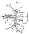
In Figur 7 ist ein zweites Ausführungsbeispiel des Scheinwerfers
dargestellt, bei dem der Scheinwerfer grundsätzlich
gleich aufgebaut ist wie vorstehend beim ersten Ausführungsbeispiel
beschrieben und zu dem nachfolgend im wesentlichen
nur die abweichenden Merkmale beschrieben werden. Die Lichtquelle
212 ist in einem Lampenträger 222 aufgenommen, der
auf der Rückseite des Reflektors 210 angeordnet ist und bezüglich
dem Reflektor 210 entlang einer geraden Linie 223 in
Richtung des in Figur 7 dargestellten Doppelpfeils bewegbar
ist, wobei die Linie 223 in dem Sinne geneigt zur optischen
Achse 211 verläuft, daß deren Abstand von der optischen
Achse 211 vertikal nach unten zum Reflektorscheitel hin zunimmt.
Am Lampenträger 222 greift ein Stellelement 242 an,
durch das die Bewegung des Lampenträgers 222 entlang der Linie
223 bewirkt wird. Das Stellelement 242 kann wie beim ersten
Ausführungsbeispiel beschrieben einen Elektromotor oder
einen Elektromagneten als Antrieb oder einen hydraulischen
oder pneumatischen Antrieb aufweisen, durch den eine Hubstange
262 in einer Längsbewegung angetrieben wird, die vorzugsweise
über ein elastisch verformbares Zwischenglied 240
am Lampenträger 222 angreift. Für den Lampenträger 222 ist
ein erster Anschlag 237 vorgesehen, an dem er in der Stellung
für Abblendlicht zur Anlage kommt, und ein zweiter Anschlag
238, an dem er in der Stellung für Fernlicht zur Anlage
kommt. Wie beim ersten Ausführungsbeispiel sind die
Stellungen für Abblendlicht und Fernlicht des Lampenträgers
222 so gewählt, daß sich der Leuchtkörper 220 der Lichtquelle
212 ausgehend von der Stellung für Abblendlicht in die
Stellung für Fernlicht in Richtung der optischen Achse 211
zum Reflektorscheitel hin und vertikal nach unten bezüglich
der optischen Achse 211 versetzt befindet. Für den Lampenträger
222 ist vorzugsweise an der Rückseite des Reflektors
210 eine Führung 234 angeordnet, in der der Lampenträger 222
zur Bewegung zwischen den beiden Stellungen geradlinig geführt
ist. Die Führung 234 kann beispielsweise durch wenigstens
eine Schiene 236 gebildet sein, in die der Lampenträger
222 mit einem Vorsprung 232 eingreift.In Figure 7 is a second embodiment of the headlamp
shown, in which the headlight basically
is constructed the same as above in the first embodiment
described and essentially below
only the different features are described. The
Die Lichtquelle 212 weist eine Umhüllung 221 auf, auf der in
deren unterem Umfangsbereich eine lichtundurchlässige Beschichtung
244 aufgebracht ist, die auch das in Lichtaustrittsrichtung
46 weisende Stirnende der Umhüllung 221 bedeckt.
Der übrige obere Umfangsbereich der Umhüllung 221 ist
lichtdurchlässig ausgebildet. Durch die oberen Ränder der
Beschichtung 244 wird wie durch die Streifen 44 beim ersten
Ausführungsbeispiel die Helldunkelgrenze des vom Reflektor
210 reflektierten Lichtbündels gebildet. Die Beschichtung
244 stellt eine Abschirmvorrichtung dar, durch die ein Teil
des vom Leuchtkörper 220 der Lichtquelle 212 ausgesandten
Lichts abgeschirmt wird, so daß es nicht auf den Reflektor
210 treffen kann. Diese Ausbildung der Lichtquelle 212,
durch die keine zusätzliche Kappe 48 wie beim ersten Ausführungsbeispiel
erforderlich ist, kann auch beim Scheinwerfer
gemäß dem ersten Ausführungsbeispiel verwendet werden. Außerdem
kann die Ausbildung der Lichtquelle 12 gemäß dem ersten
Ausführungsbeispiel auch beim Scheinwerfer gemäß dem
zweiten Ausführungsbeispiel verwendet werden, wobei dann
auch die Kappe 48 vorgesehen ist, die einstückig mit dem
Lampenträger 222 oder starr mit diesem verbunden sein kann.The
Die vom Scheinwerfer gemäß dem zweiten Ausführungsbeispiel
in der Stellung für Abblendlicht und in der Stellung für
Fernlicht ausgesandten Lichtbündel beleuchten den Meßschirm
50 in gleicher Weise wie in den Figuren 2 bis 5 dargestellt,
da die Bewegung der Lichtquelle 212 zwischen den gleichen
Stellungen erfolgt und nur das Stellelement 242 unterschiedlich
ausgebildet ist.The headlight according to the second embodiment
in the low beam position and in the
Beams of high-beam light illuminate the
In den Figuren 8 und 9 ist der Scheinwerfer gemäß einem
dritten Ausführungsbeispiel dargestellt, wobei der Scheinwerfer
grundsätzlich ebenfalls gleich aufgebaut ist wie beim
ersten Ausführungsbeispiel beschrieben und daher nachfolgend
im wesentlichen nur die abweichenden Merkmale beschrieben
werden. Der Scheinwerfer weist den Reflektor 310 sowie die
Lichtquelle 312 auf, die im Lampenträger 322 angeordnet ist.
Die Umhüllung 321 der Lichtquelle 312 ist über ihren gesamten
Umfang lichtdurchlässig ausgebildet. Am Lampenträger 322
ist eine Kappe 348 befestigt, die in den Reflektor 310 ragt
und die die Lichtquelle 312 auf ihrem unteren Umfangsbereich
umgibt. Die Kappe 348 kann im Schnitt quer zur optischen
Achse 311 beispielsweise u-förmig oder in Form eines Kreisabschnitts
ausgebildet sein. Die Kappe 348 ist lichtundurchlässig
ausgebildet und weist in Richtung der optischen Achse
311 mehrere hintereinander angeordnete schlitzartige Öffnungen
370 auf, die sich über den Umfang der Kappe 348 bis nahe
an deren obere Ränder 344 erstrecken und die durch Stege 371
voneinander getrennt sind. Innerhalb der Kappe 348 ist ein
schieberartiger Einsatz 373 angeordnet, der nahe dem inneren
Umfang der Kappe 348 angeordnet ist und relativ zu dem die
Kappe 348 in Längsrichtung bewegbar ist. Der Schieber 373
ist ebenfalls lichtundurchlässig ausgebildet und weist mehrere
in Richtung der optischen Achse 311 hintereinander angeordnete,
schlitzartige Öffnungen 374 auf, die durch Stege
375 voneinander getrennt sind. Die Kappe 348 bildet zusammen
mit dem Schieber 373 eine Abschirmvorrichtung. Am zum Reflektorscheitel
hin angeordneten Endbereich des Schiebers
373 greift in eine Ausnehmung quer zur optischen Achse 311
ein Fixierelement 377 mit einer Nase ein, so daß der Schieber
373 in einer Stellung in Richtung der optischen Achse
311 festgelegt ist. Das Fixierelement 377 ist beispielsweise
in Form einer Platte ausgebildet, die über den Rand der Öffnung
318 im Scheitelbereich des Reflektors 310 auf der Rückseite
des Reflektors 310 hinausragt und mittels einer
Schraube 378 an der Rückseite des Reflektors 310 befestigt
ist. Am Reflektor 310 ist eine Strahlenblende 380 befestigt,
durch die von der Lichtquelle 312 direkt in Lichtaustrittsrichtung
46 austretendes, nicht auf den Reflektor 310 treffendes
Licht abgeschirmt wird.In Figures 8 and 9, the headlamp is according to a
shown third embodiment, the headlight
is also basically the same as the
described first embodiment and therefore below
essentially only the different features are described
become. The headlight has the
Der Lampenträger 322 ist in seinem oberen Randbereich wie
beim ersten Ausführungsbeispiel an den Trägern 328 um die
Achse 330 schwenkbar gelagert. An seinem unteren Randbereich
weist der Lampenträger 322 eine Gewindebohrung 332 auf, in
die eine Schraube 334 eingedreht ist, die einen zur Rückseite
des Reflektors 310 weisenden Kopf 336 aufweist und an
ihrem anderen Ende einen Schlitz 338 aufweist. Das Stellelement
342 weist als Antrieb einen Elektromotor 360 auf, der
mit seiner Welle 361 senkrecht zur optischen Achse 311 und
horizontal angeordnet ist. Mit der Welle 361 ist eine Kurvenscheibe
362 drehfest verbunden, die über ihren Umfang mit
veränderlichem Abstand zur Welle 361 verläuft. Am Lampenträger
322 ist eine Zugfeder 379 eingehängt, die andererseits
am Fixierelement 377 eingehängt ist und durch die der Kopf
336 der Schraube 334 in der Anlage an der Kurvenscheibe 362
gehalten wird. Durch ein Hinein- oder Herausdrehen der
Schraube 334 ist eine Grundeinstellung der Stellung des
Lampenträgers 322 und damit der in diesem angeordneten
Lichtquelle 312 ermöglicht.The
Die Anordnung nach Figuren 8, 9, 10, 11 kann auch mit Stellelementen und Anlenksystemen der Figuren 1 und 6 getätigt werden.The arrangement according to FIGS. 8, 9, 10, 11 can also be made with adjusting elements and articulation systems of Figures 1 and 6 become.
In Figur 8 ist der Scheinwerfer in der Stellung für Abblendlicht
dargestellt, in der die Kurvenscheibe 362 sich in einer
solchen Drehstellung befindet, daß der Kopf 336 der
Schraube 334 an dem Umfangsbereich der Kurvenscheibe 362 anliegt,
der den geringsten Abstand von der Welle 361 aufweist.
Die Lichtquelle 312 ist dabei so angeordnet, daß sich
deren Leuchtkörper 320 etwa auf der optischen Achse 311 befindet.
Der Schieber 373 ist in der Kappe 348 so angeordnet,
daß dessen Stege 375 die Schlitze 370 der Kappe 348 überdecken,
so daß von der Lichtquelle 312 in deren unterem Umfangsbereich
ausgesandtes Licht nicht durch die vom Schieber
373 und der Kappe 348 gebildete Abschirmvorrichtung hindurchtreten
und auf einen unteren Bereich des Reflektors 310
treffen kann. Durch die oberen Ränder 344 der Kappe 348 wird
die obere Helldunkelgrenze des Abblendlichtbündels gebildet.In Figure 8, the headlamp is in the low beam position
shown, in which the
In Figur 9 ist der Scheinwerfer in einer Stellung für Fernlicht
dargestellt, in der sich die Kurvenscheibe 362 in einer
solchen Drehstellung befindet, daß der Kopf 336 der
Schraube 334 in einem Umfangsbereich der Kurvenscheibe 362
anliegt, der mit größerem Abstand von der Welle 361 angeordnet
ist. Der Lampenträger 322 ist dabei um die Achse 330
derart geschwenkt, daß der Leuchtkörper 320 der Lichtquelle
312 gegenüber der Stellung für Abblendlicht in Richtung der
optischen Achse 311 zum Reflektorscheitel hin und vertikal
zur optischen Achse 311 nach unten versetzt angeordnet ist.
Die Kappe 348 führt wegen ihrer starren Verbindung mit dem
Lampenträger 322 die Schwenkbewegung ebenfalls aus, während
der Schieber 373 durch das Fixierelement 377 bedingt nicht
bewegt werden kann. Es ergibt sich somit eine Bewegung der
Kappe 348 relativ zum Schieber 373, so daß die Schlitze 370
der Kappe 348 in der Stellung für Fernlicht nicht mehr von
den Stegen 375 des Schiebers 373 verdeckt werden, sondern
die Schlitze 374 des Schiebers 373 mit denen der Kappe 348
fluchten und von der Lichtquelle 312 in deren unterem Umfangsbereich
ausgesandtes Licht durch die Schlitze 370,374
hindurchtreten und auf den unteren Bereich des Reflektors
310 treffen kann. Für die Erzeugung des Fernlichts kann somit
zusätzlich auch der untere Bereich des Reflektors 310
genutzt werden.In Figure 9, the headlamp is in a high beam position
shown, in which the
Beim der vorstehend beschriebenen Ausführung des Scheinwerfers
gemäß dem dritten Ausführungsbeispiel ergibt sich die
Bewegung der durch die Kappe 348 und den Schieber 373 gebildeten
Abschirmvorrichtung zwischen ihrer Stellung für Abblendlicht
und ihrer Stellung für Fernlicht zwangsläufig mit
der Bewegung der Lichtquelle 312, so daß hierfür kein zusätzliches
Stellelement erforderlich ist. Die vom Reflektor
310 reflektierten bzw. aus dem Scheinwerfer nach Durchtritt
durch die Abdeckscheibe 16 austretenden Lichtbündel beleuchten
den Meßschirm 50 wie in den Figuren 2 bis 5 dargestellt.In the headlight version described above
according to the third embodiment, the
Movement of those formed by
In den Figuren 10 und 11 ist der Scheinwerfer gemäß einem
dritten Ausführungsbeispiel dargestellt, zu dem nachfolgend
nur die modifizierte Abschirmvorrichtung beschrieben wird.
Die Lichtquelle 412 ist im Lampenträger 422 angeordnet, der
wie bei einem der vorstehend beschriebenen Ausführungsbeispiele
ausgebildet sein kann und in einer Schwenkbewegung
oder wie bei der Ausführung gemäß Figur 7 geradlinig zwischen
der Stellung für Abblendlicht und der Stellung für
Fernlicht bewegbar ist. Als Abschirmvorrichtung, durch die
in der Stellung für Abblendlicht von der Lichtquelle 412 auf
deren unterem Umfangsbereich ausgesandtes Licht abgeschirmt
wird, so daß es nicht auf den unteren Bereich des Reflektors
410 treffen kann, dienen beim Scheinwerfer gemäß dem vierten
Ausführungsbeispiel zwei flügelartige Teile 448, die sich
entlang der optischen Achse 411 erstrecken und die in einer
die optische Achse 411 enthaltenden, etwa vertikalen Ebene
478 getrennt sind. Die Flügel 448 sind in ihrem oberen Bereich
am Reflektor 410 oder an einem am Reflektor 410 befestigten
Träger 480 um jeweils eine sich etwa parallel zur
optischen Achse 411 erstreckende Achse schwenkbar gelagert.
In ihrem oberen Bereich sind die Flügel 448 nur als schmale
Stege 481 ausgebildet, so daß sie nur wenig von der Lichtquelle
412 in ihrem oberen Umfangsbereich ausgesandtes Licht
abschirmen. In ihrem unteren Bereich 482 sind die Flügel 448
jedoch halbschalenartig geschlossen und lichtundurchlässig
ausgebildet. Auf die Oberseite der Stege 481 der Flügel 448
wirkt eine vorgespannte etwa c-förmige Feder 484, durch die
die Halbschalen 482 zueinander hin gedrückt werden. Die Feder
484 ist am Träger 480 gehalten. Am Lampenträger 422 ist
zu beiden Seiten neben der Lichtquelle 412 jeweils ein
lichtundurchlässiger Steg 444 befestigt, die sich etwa
parallel zur Längsachse der Lichtquelle 412 erstrecken. Die
Stege 444 können auch an der Lichtquelle 412 befestigt sein.In Figures 10 and 11, the headlamp is according to a
shown third embodiment, to the following
only the modified shielding device is described.
The
In Figur 10 ist die Abschirmvorrichtung in ihrer Stellung
für Abblendlicht dargestellt, in der die Flügel 448 durch
die Feder 484 bewirkt mit ihren Halbschalen 482 aneinander
anliegen und eine geschlossene Schale bilden, so daß von der
Lichtquelle 412 in ihrem unteren Umfangsbereich ausgesandtes
Licht nicht austreten und auf den unteren Bereich des Reflektors
410 treffen kann. Die oberen Ränder der Stege 444
ragen dabei über die geschlossenen unteren Bereiche der
Halbschalen 482 hinaus und bilden die Helldunkelgrenze des
Abblendlichtbündels.In Figure 10, the shielding device is in its position
shown for low beam in which the
In Figur 11 ist die Abschirmvorrichtung in ihrer Stellung
für Fernlicht dargestellt, in der die Lichtquelle 412 und
die Stege 444 bezüglich der optischen Achse 411 vertikal
nach unten versetzt angeordnet sind. Die Stege 444 kommen
dabei an den Innenseiten der Halbschalen 482 zur Anlage und
drücken diese gegen die Kraft der Feder 484 auseinander, wobei
die Flügel 448 um ihre Achsen schwenken, so daß eine
Öffnung freigegeben wird, durch die auch von der Lichtquelle
412 in ihrem unteren Umfangsbereich ausgesandtes Licht austreten
und auf den unteren Bereich des Reflektors 410 treffen
kann. Die Stege 444 sind dann im Schatten der Halbschalen
482 angeordnet.In Figure 11 the shielding device is in its position
shown for high beam, in which the
Auch beim Scheinwerfer gemäß dem vierten Ausführungsbeispiel
wird die durch die beiden Flügel 448 gebildete Abschirmvorrichtung
bei der Bewegung der Lichtquelle 412 zwischen ihrer
Stellung für Abblendlicht und ihrer Stellung für Fernlicht
zwangsläufig ebenfalls zwischen ihrer Stellung für Abblendlicht
und ihrer Stellung für Fernlicht mitbewegt, so daß
hierzu kein gesondertes Stellelement erforderlich ist. Die
vom Reflektor 410 reflektierten bzw. aus dem Scheinwerfer
nach Durchtritt durch die Abdeckscheibe 16 austretenden
Lichtbündel beleuchten den Meßschirm 50 wie in den Figuren 2
bis 5 dargestellt.Also in the headlamp according to the fourth embodiment
becomes the shielding device formed by the two
Bei den Ausführungen des Scheinwerfers gemäß den Figuren 8 bis 11 können auch die Stellelemente und/oder die Abblendsysteme gemäß den Figuren 1 und 6 verwendet werden.In the designs of the headlamp according to FIGS. 8 to 11 can also the control elements and / or the anti-dazzle systems can be used according to Figures 1 and 6.
Claims (14)
- Low/high beam headlight for vehicles, having a reflector (10; 210) and having a light source (12; 212) in the form of a gas discharge lamp, which can be moved by an actuator (42; 142; 242) relative to the reflector (10; 210) between a position for low beam and a position for high beam, in the direction of the optical axis (11;211) of the reflector (10;210) and can additionally be moved vertically in relation to the optical axis (11;211), characterized in that provision is made for a movable shielding device (44,48;244) which is assigned to the light source (12;212), by means of which, at least in the position of the light source (12;212) for low beam, part of the light emitted by the light source (12;212) is shielded and an upper light/dark boundary (54, 55) of the low beam exiting from the headlight is generated, the shielding device (44,48;244) being able to be moved by the same actuator (42;142;242) as the light source (12;212).
- Headlight according to Claim 1, characterized in that the light source (12;212) has an at least partially translucent covering (21;221) on which there is partially applied an opaque coating (44;244) which at least partially forms the shielding device.
- Headlight according to Claim 2, characterized in that additionally an opaque cap 948) is provided which, together with the coating (44), forms the shielding device.
- Headlight according to one of the preceding claims, characterized in that the light source (12;212) is arranged rigidly in a lamp carrier (22;222) and in that the lamp carrier (22;222) can be moved by the actuator (42;142;242) engaging on the latter.
- Headlight according to Claim 3 and 4, characterized in that the cap (48) is rigidly connected to the lamp carrier (22).
- Headlight according to Claim 4 or 5, characterized in that the lamp carrier (22) is supported so as to be able to pivot about an axis (30) extending approximately horizontally and in that the actuator (42) engages on the lamp carrier (22) eccentrically in relation to this axis (30).
- Headlight according to Claim 4 or 5, characterized in that the lamp carrier (222) can be moved in a straight line between the position for low beam and the position for high beam.
- Headlight according to one of Claims 4 to 7, characterized in that the lamp carrier (22;222) is brought by the actuator (42;242), in the position for low beam, into contact with a fixed stop (37;237) and/or, in the position for high beam, into contact with a further fixed stop (38;238).
- Headlight according to Claim 8, characterized in that there is arranged between the lamp carrier (22;222) and the actuator (42;142;242) an elastically deformable intermediate element (40;240) which, in at least one position of the lamp carrier (22;222), is deformed in such a way that the lamp carrier (22;222) is held under pretension in contact with one of the stops (37;237;38;238).
- Headlight according to one of Claims 4 to 9, characterized in that the actuator (42;142;242) has an electric motor (60;160;260) as drive.
- Headlight according to Claim 10, characterized in that the electric motor (42) is coupled to the lamp carrier (22) via a transmission element (62) articulated eccentrically to the shaft (61) of the electric motor.
- Headlight according to Claim 1, characterized in that the shielding device has an opaque cap (348) which can be moved together with the light source (312), which has at least one opening (370) and a further opaque part (373) which is fixed in relation to the reflector (310), by means of which part, in the position for low beam, the opening (370) of the cap (348) is covered, and in that the cap (348), in the position for high beam, is arranged in such a way that its opening (370) is exposed.
- Headlight according to Claim 1, characterized in that the screening device has two pivotable, wing-like parts (448) which, in their position for low beam, adjoin each other to form a continuous cap, so that light emitted by the light source (412) towards a partial region of the reflector (410) is shielded, and in that at least one part (444) which can be moved together with the light source (412) is provided, by means of which the wing-like parts (448) can be moved away from each other, during the movement of the light source (412) into its position for high beam, to expose an opening through which light emitted by the light source (412) can impinge on the partial region of the reflector (410).
- Headlight according to Claim 13, characterized in that a resilient element (484) is provided, by means of which the wing-like parts (448) are loaded towards each other to form the cap.
Applications Claiming Priority (2)
| Application Number | Priority Date | Filing Date | Title |
|---|---|---|---|
| DE4435507A DE4435507A1 (en) | 1994-10-04 | 1994-10-04 | Low beam and high beam headlights for vehicles |
| DE4435507 | 1994-10-04 |
Publications (3)
| Publication Number | Publication Date |
|---|---|
| EP0705730A2 EP0705730A2 (en) | 1996-04-10 |
| EP0705730A3 EP0705730A3 (en) | 1996-10-02 |
| EP0705730B1 true EP0705730B1 (en) | 2000-06-07 |
Family
ID=6529959
Family Applications (1)
| Application Number | Title | Priority Date | Filing Date |
|---|---|---|---|
| EP95114689A Expired - Lifetime EP0705730B1 (en) | 1994-10-04 | 1995-09-19 | Headlight with dipped and distance light for vehicle |
Country Status (4)
| Country | Link |
|---|---|
| US (1) | US5769525A (en) |
| EP (1) | EP0705730B1 (en) |
| JP (1) | JP3919244B2 (en) |
| DE (2) | DE4435507A1 (en) |
Families Citing this family (54)
| Publication number | Priority date | Publication date | Assignee | Title |
|---|---|---|---|---|
| JPH1092208A (en) * | 1996-09-20 | 1998-04-10 | Stanley Electric Co Ltd | Headlight for vehicle |
| JP2965930B2 (en) * | 1997-03-07 | 1999-10-18 | スタンレー電気株式会社 | Vehicle headlights |
| DE19710632A1 (en) * | 1997-03-14 | 1998-09-17 | Bosch Gmbh Robert | Vehicle headlamp for full beam and dipped beam |
| FR2765310B1 (en) | 1997-06-30 | 1999-10-22 | Valeo Vision | MOTOR VEHICLE PROJECTOR CAPABLE OF EMITTING TWO DIFFERENT BEAMS WITH A SINGLE LIGHT SOURCE |
| FR2769687B1 (en) * | 1997-10-13 | 2000-03-03 | Valeo Vision | LEFT AND RIGHT MOTOR VEHICLE ASSEMBLY WITH IMPROVED PHOTOMETRIC PROPERTIES |
| US6186650B1 (en) * | 1997-12-09 | 2001-02-13 | Cooper Automotive Products, Inc. | Vehicle headlamp with beamforming waveguide |
| FR2772883B1 (en) * | 1997-12-19 | 2000-03-10 | Valeo Vision | MOTOR VEHICLE PROJECTOR WITH SINGLE MIRROR AND MOVABLE SOURCE FOR GENERATING TWO DIFFERENT LIGHTING BEAMS |
| JPH11240379A (en) * | 1997-12-24 | 1999-09-07 | Koito Mfg Co Ltd | Head lamp for vehicle |
| DE19805660A1 (en) | 1998-02-12 | 1999-08-19 | Bosch Gmbh Robert | Headlamps for low and high beam vehicles |
| DE19805852C2 (en) | 1998-02-13 | 1999-12-23 | Bosch Gmbh Robert | Motor vehicle headlights with a movable light source for setting low and high beams |
| ITTO980197A1 (en) * | 1998-03-10 | 1999-09-10 | Magneti Marelli Spa | MOTOR VEHICLE PROJECTOR. |
| DE19814788B4 (en) * | 1998-04-02 | 2009-01-29 | Automotive Lighting Reutlingen Gmbh | Vehicle headlights for dipped beam and high beam |
| DE19825375C2 (en) * | 1998-06-06 | 2000-07-06 | Bosch Gmbh Robert | Headlights with gas discharge lamp that can be faded in and out, especially for motor vehicles |
| DE19829358C1 (en) * | 1998-07-01 | 2000-02-24 | Bosch Gmbh Robert | Headlamp apparatus of motor vehicle, has reflector element which reflects non-effective light beam towards front side of vehicle on road surface, through diffusion plate |
| DE19833431C2 (en) | 1998-07-24 | 2000-07-27 | Bosch Gmbh Robert | Motor vehicle headlights for low and high beams with a position-adjustable light source |
| JP2000043639A (en) | 1998-07-29 | 2000-02-15 | Stanley Electric Co Ltd | Headlight for vehicle |
| JP2000071864A (en) | 1998-08-28 | 2000-03-07 | Stanley Electric Co Ltd | Head lamp with light distribution switching device |
| JP2000090721A (en) * | 1998-09-17 | 2000-03-31 | Koito Mfg Co Ltd | Vehicular headlamp |
| JP3943261B2 (en) * | 1998-09-17 | 2007-07-11 | 株式会社小糸製作所 | Vehicle headlamp |
| US6190029B1 (en) | 1998-09-25 | 2001-02-20 | Stanley Electric Co., Ltd. | Headlamp with beam distribution switch mechanism |
| DE19844839B4 (en) * | 1998-09-30 | 2010-07-22 | Automotive Lighting Reutlingen Gmbh | Headlights for vehicles |
| DE19860461B4 (en) * | 1998-12-28 | 2012-09-27 | Automotive Lighting Reutlingen Gmbh | Headlamp system for vehicles for generating light bundles with different characteristics |
| DE19900605A1 (en) | 1999-01-11 | 2000-07-13 | Bosch Gmbh Robert | Vehicle headlamp for different light beams has source arranged in extra position(s) so beam from source is reflected with shorter range and lower maximum intensity than dipped beam |
| DE19907393C2 (en) | 1999-02-20 | 2001-02-01 | Bosch Gmbh Robert | Motor vehicle headlights for low and high beams with a position-adjustable light source |
| DE19924317B4 (en) * | 1999-05-27 | 2005-06-23 | Automotive Lighting Reutlingen Gmbh | Motor vehicle headlight for dipped beam and high beam |
| CZ9902352A3 (en) * | 1999-06-29 | 2001-02-14 | Autopal, S. R. O. | Headlight system for motor vehicles |
| CZ9902387A3 (en) | 1999-07-01 | 2001-02-14 | Autopal, S. R. O. | Headlight for motor vehicles |
| EP1069374B1 (en) * | 1999-07-16 | 2005-08-31 | Automotive Lighting Italia Spa | Motor-vehicle adaptive head-lamp having a central adjustable diaphragm |
| DE19933662B4 (en) | 1999-07-17 | 2011-12-22 | Automotive Lighting Reutlingen Gmbh | Headlamp for vehicles for dipped beam and at least one additional light function |
| JP3638864B2 (en) * | 2000-01-31 | 2005-04-13 | 株式会社小糸製作所 | Vehicle headlamp |
| CZ297958B6 (en) * | 2000-02-28 | 2007-05-09 | Autopal, S. R. O. | Headlight for motor vehicles |
| DE10017658A1 (en) | 2000-04-08 | 2001-10-11 | Bosch Gmbh Robert | Motor vehicle head-lamp with variable light-beam, includes an adjustment device for varying the relative arrangement between the light source and the reflector for dipped- and high-beam |
| CZ297454B6 (en) | 2000-05-09 | 2006-12-13 | Autopal, S. R. O. | Headlight for motor vehicles |
| HK1026113A2 (en) | 2000-07-20 | 2000-10-27 | Lun Cheung Leung | Vehicle lamp provided with an anti-vibration apparatus |
| DE10040573B4 (en) | 2000-08-18 | 2014-05-08 | Automotive Lighting Reutlingen Gmbh | Headlamp for vehicles for generating a dipped beam and at least one light beam with a longer range |
| US6547429B2 (en) * | 2000-09-01 | 2003-04-15 | Guide Corporation | Bi-functional tilted axis reflector headlamp |
| JP4015356B2 (en) | 2000-10-27 | 2007-11-28 | 株式会社小糸製作所 | Vehicle lamp device |
| DE10137837A1 (en) * | 2001-08-02 | 2003-02-13 | Philips Corp Intellectual Pty | Discharge lamp and headlights for a motor vehicle |
| DE10163376A1 (en) * | 2001-12-21 | 2003-07-10 | Hella Kg Hueck & Co | Vehicle headlamp operates on projection principle and has lens attachment arrangement that is decoupled from reflector attachment arrangement |
| KR100501575B1 (en) * | 2002-11-13 | 2005-07-18 | 현대자동차주식회사 | A slope plate type head lamp leveling device |
| CZ298495B6 (en) * | 2003-04-08 | 2007-10-17 | Visteon Global Technologies, Inc. | Optimization of full-beam light of motor vehicle headlights and motor vehicle headlight per se |
| US20050152151A1 (en) * | 2004-01-14 | 2005-07-14 | Guide Corporation | Adverse weather automatic sign light shield |
| US7264372B2 (en) * | 2004-03-16 | 2007-09-04 | Mag Instrument, Inc. | Apparatus and method for aligning a substantial point source of light with a reflector feature |
| US7290907B2 (en) * | 2006-02-24 | 2007-11-06 | Honda Motor Co., Ltd | Vehicle headlamp with daytime running light |
| JP4997052B2 (en) * | 2007-10-01 | 2012-08-08 | 株式会社小糸製作所 | Vehicle headlamp |
| DE102007053399A1 (en) * | 2007-11-09 | 2009-05-14 | Continental Automotive Gmbh | Headlamp with adaptable light guide |
| US8070338B2 (en) * | 2008-04-07 | 2011-12-06 | General Electric Company | Three-mode integrated headlamp |
| US8366290B2 (en) * | 2009-01-14 | 2013-02-05 | Mag Instrument, Inc. | Portable lighting device |
| CN103162205B (en) * | 2011-12-15 | 2016-07-13 | 海洋王照明科技股份有限公司 | Light fixture |
| US9310042B2 (en) * | 2012-10-24 | 2016-04-12 | Koito Manufacturing Co., Ltd. | Vehicle headlamp |
| FR2998943B1 (en) * | 2012-11-30 | 2018-07-13 | Valeo Illuminacion | LIGHTING AND / OR SIGNALING DEVICE FOR MOTOR VEHICLE |
| KR20210016166A (en) * | 2019-08-01 | 2021-02-15 | 현대자동차주식회사 | Illumination apparatus for vehicle |
| US11454374B2 (en) | 2019-08-01 | 2022-09-27 | Hyundai Motor Company | Illumination apparatus for mobility |
| EP4345369A1 (en) * | 2022-09-28 | 2024-04-03 | ZKW Group GmbH | Illumination device for a vehicle headlamp |
Family Cites Families (7)
| Publication number | Priority date | Publication date | Assignee | Title |
|---|---|---|---|---|
| GB492267A (en) * | 1937-03-13 | 1938-09-13 | Samuel James Jacks | Improvements in or relating to lamps or light projectors |
| FR842383A (en) * | 1938-02-12 | 1939-06-12 | Lighting device for vehicles | |
| GB966789A (en) | 1961-05-04 | 1964-08-19 | Cibie Pierre | Improved headlamp with double beams |
| US3953726A (en) * | 1974-12-06 | 1976-04-27 | Scarritt Sr Frank M | Infinitely adjustable level light |
| JPS6293802A (en) * | 1985-10-18 | 1987-04-30 | 東芝ライテック株式会社 | Head lamp for vehicle |
| US4947078A (en) * | 1989-06-05 | 1990-08-07 | General Motors Corporation | Sealed beam headlamp |
| IT1256983B (en) * | 1992-10-27 | 1995-12-27 | Carello Spa | MOTOR VEHICLE PROJECTOR. |
-
1994
- 1994-10-04 DE DE4435507A patent/DE4435507A1/en not_active Withdrawn
-
1995
- 1995-09-19 DE DE59508449T patent/DE59508449D1/en not_active Expired - Fee Related
- 1995-09-19 EP EP95114689A patent/EP0705730B1/en not_active Expired - Lifetime
- 1995-09-27 US US08/534,728 patent/US5769525A/en not_active Expired - Fee Related
- 1995-10-04 JP JP25791295A patent/JP3919244B2/en not_active Expired - Fee Related
Also Published As
| Publication number | Publication date |
|---|---|
| JP3919244B2 (en) | 2007-05-23 |
| DE4435507A1 (en) | 1996-04-11 |
| JPH08111101A (en) | 1996-04-30 |
| EP0705730A3 (en) | 1996-10-02 |
| US5769525A (en) | 1998-06-23 |
| EP0705730A2 (en) | 1996-04-10 |
| DE59508449D1 (en) | 2000-07-13 |
Similar Documents
| Publication | Publication Date | Title |
|---|---|---|
| EP0705730B1 (en) | Headlight with dipped and distance light for vehicle | |
| EP0723108B1 (en) | Vehicle headlamp | |
| EP0937942B1 (en) | Projection type motor vehicle headlamp | |
| DE3729515C2 (en) | ||
| DE19537838A1 (en) | Motor vehicle headlamp design | |
| DE19756437A1 (en) | Vehicle headlamp with high and dipped beam settings | |
| DE4418135B4 (en) | Motor vehicle headlight with variable light distribution | |
| DE10123618A1 (en) | Vehicle headlights | |
| DE4229728C1 (en) | Dual-reflector headlamp assembly for vehicle - has cut=outs in edge of dipped beam reflector to illuminate driving beam reflector | |
| AT412994B (en) | VEHICLE HEADLIGHTS | |
| DE4435446A1 (en) | Motor vehicle headlamp | |
| DE19933662A1 (en) | Headlamp for vehicles for dipped beam and at least one further light function has in light exit direction after adjusting device, additional reflector in which additional light source is arranged transversely to optical axis | |
| DE10004701A1 (en) | Headlights for vehicles according to the projection principle | |
| AT413752B (en) | VEHICLE HEADLIGHTS | |
| DE19947876B4 (en) | Headlights for vehicles | |
| EP0590454B1 (en) | Headlamp for vehicles | |
| WO1999002917A1 (en) | Low beam headlamps and high beam headlamps for vehicles | |
| DE19817348A1 (en) | Illumination arrangement for motor vehicle front headlamps can be installed even where space is limited and enables simple adjustment of the headlamp beam direction | |
| DE19600613A1 (en) | Motor vehicle headlamp | |
| EP0731314B1 (en) | Headlamp for vehicles | |
| DE19610904A1 (en) | Low beam headlights for vehicles | |
| DE19750495A1 (en) | Head lamp system for vehicle with at least one dipped lamp and one main beam lamp | |
| DE10009590A1 (en) | Headlamp unit for motor vehicle has additional light fitting whose light source is operated at lower than normal power in addition to that of dipped light unit when producing dipped beam | |
| DE19616037A1 (en) | Vehicle headlamp with dipped and beam | |
| DE19814788B4 (en) | Vehicle headlights for dipped beam and high beam |
Legal Events
| Date | Code | Title | Description |
|---|---|---|---|
| PUAI | Public reference made under article 153(3) epc to a published international application that has entered the european phase |
Free format text: ORIGINAL CODE: 0009012 |
|
| AK | Designated contracting states |
Kind code of ref document: A2 Designated state(s): DE FR GB IT |
|
| PUAL | Search report despatched |
Free format text: ORIGINAL CODE: 0009013 |
|
| AK | Designated contracting states |
Kind code of ref document: A3 Designated state(s): DE FR GB IT |
|
| 17P | Request for examination filed |
Effective date: 19970402 |
|
| 17Q | First examination report despatched |
Effective date: 19981014 |
|
| GRAG | Despatch of communication of intention to grant |
Free format text: ORIGINAL CODE: EPIDOS AGRA |
|
| GRAG | Despatch of communication of intention to grant |
Free format text: ORIGINAL CODE: EPIDOS AGRA |
|
| GRAH | Despatch of communication of intention to grant a patent |
Free format text: ORIGINAL CODE: EPIDOS IGRA |
|
| GRAH | Despatch of communication of intention to grant a patent |
Free format text: ORIGINAL CODE: EPIDOS IGRA |
|
| GRAA | (expected) grant |
Free format text: ORIGINAL CODE: 0009210 |
|
| AK | Designated contracting states |
Kind code of ref document: B1 Designated state(s): DE FR GB IT |
|
| RIC1 | Information provided on ipc code assigned before grant |
Free format text: 7B 60Q 1/14 A, 7F 21V 7/16 B |
|
| REF | Corresponds to: |
Ref document number: 59508449 Country of ref document: DE Date of ref document: 20000713 |
|
| ITF | It: translation for a ep patent filed |
Owner name: STUDIO JAUMANN P. & C. S.N.C. |
|
| GBT | Gb: translation of ep patent filed (gb section 77(6)(a)/1977) |
Effective date: 20000816 |
|
| ET | Fr: translation filed | ||
| PG25 | Lapsed in a contracting state [announced via postgrant information from national office to epo] |
Ref country code: GB Free format text: LAPSE BECAUSE OF NON-PAYMENT OF DUE FEES Effective date: 20000919 |
|
| PLBE | No opposition filed within time limit |
Free format text: ORIGINAL CODE: 0009261 |
|
| STAA | Information on the status of an ep patent application or granted ep patent |
Free format text: STATUS: NO OPPOSITION FILED WITHIN TIME LIMIT |
|
| GBPC | Gb: european patent ceased through non-payment of renewal fee |
Effective date: 20000919 |
|
| 26N | No opposition filed | ||
| REG | Reference to a national code |
Ref country code: FR Ref legal event code: ST |
|
| REG | Reference to a national code |
Ref country code: FR Ref legal event code: RN |
|
| REG | Reference to a national code |
Ref country code: FR Ref legal event code: FC |
|
| PGFP | Annual fee paid to national office [announced via postgrant information from national office to epo] |
Ref country code: FR Payment date: 20030918 Year of fee payment: 9 |
|
| PG25 | Lapsed in a contracting state [announced via postgrant information from national office to epo] |
Ref country code: FR Free format text: LAPSE BECAUSE OF NON-PAYMENT OF DUE FEES Effective date: 20050531 |
|
| REG | Reference to a national code |
Ref country code: FR Ref legal event code: ST |
|
| PG25 | Lapsed in a contracting state [announced via postgrant information from national office to epo] |
Ref country code: IT Free format text: LAPSE BECAUSE OF NON-PAYMENT OF DUE FEES Effective date: 20050919 |
|
| PGFP | Annual fee paid to national office [announced via postgrant information from national office to epo] |
Ref country code: DE Payment date: 20071122 Year of fee payment: 13 |
|
| PG25 | Lapsed in a contracting state [announced via postgrant information from national office to epo] |
Ref country code: DE Free format text: LAPSE BECAUSE OF NON-PAYMENT OF DUE FEES Effective date: 20090401 |