EP1069374B1 - Motor-vehicle adaptive head-lamp having a central adjustable diaphragm - Google Patents
Motor-vehicle adaptive head-lamp having a central adjustable diaphragm Download PDFInfo
- Publication number
- EP1069374B1 EP1069374B1 EP99830455A EP99830455A EP1069374B1 EP 1069374 B1 EP1069374 B1 EP 1069374B1 EP 99830455 A EP99830455 A EP 99830455A EP 99830455 A EP99830455 A EP 99830455A EP 1069374 B1 EP1069374 B1 EP 1069374B1
- Authority
- EP
- European Patent Office
- Prior art keywords
- diaphragm
- head
- motor
- lamp
- reflector
- Prior art date
- Legal status (The legal status is an assumption and is not a legal conclusion. Google has not performed a legal analysis and makes no representation as to the accuracy of the status listed.)
- Expired - Lifetime
Links
- 230000003044 adaptive effect Effects 0.000 title description 3
- 230000003287 optical effect Effects 0.000 claims description 6
- 238000010586 diagram Methods 0.000 description 3
- 238000010276 construction Methods 0.000 description 2
- 238000005286 illumination Methods 0.000 description 2
- 230000004913 activation Effects 0.000 description 1
- 238000012217 deletion Methods 0.000 description 1
- 230000037430 deletion Effects 0.000 description 1
- 239000000463 material Substances 0.000 description 1
- 239000002184 metal Substances 0.000 description 1
- 238000012544 monitoring process Methods 0.000 description 1
Images
Classifications
-
- F—MECHANICAL ENGINEERING; LIGHTING; HEATING; WEAPONS; BLASTING
- F21—LIGHTING
- F21S—NON-PORTABLE LIGHTING DEVICES; SYSTEMS THEREOF; VEHICLE LIGHTING DEVICES SPECIALLY ADAPTED FOR VEHICLE EXTERIORS
- F21S41/00—Illuminating devices specially adapted for vehicle exteriors, e.g. headlamps
- F21S41/60—Illuminating devices specially adapted for vehicle exteriors, e.g. headlamps characterised by a variable light distribution
- F21S41/68—Illuminating devices specially adapted for vehicle exteriors, e.g. headlamps characterised by a variable light distribution by acting on screens
- F21S41/683—Illuminating devices specially adapted for vehicle exteriors, e.g. headlamps characterised by a variable light distribution by acting on screens by moving screens
- F21S41/692—Shields, i.e. screens not creating an image meant to be projected
-
- F—MECHANICAL ENGINEERING; LIGHTING; HEATING; WEAPONS; BLASTING
- F21—LIGHTING
- F21S—NON-PORTABLE LIGHTING DEVICES; SYSTEMS THEREOF; VEHICLE LIGHTING DEVICES SPECIALLY ADAPTED FOR VEHICLE EXTERIORS
- F21S41/00—Illuminating devices specially adapted for vehicle exteriors, e.g. headlamps
- F21S41/20—Illuminating devices specially adapted for vehicle exteriors, e.g. headlamps characterised by refractors, transparent cover plates, light guides or filters
- F21S41/28—Cover glass
Definitions
- the present invention relates to motor-vehicle head-lamps, of the type indicated in the pre-characterizing portion of claim 1.
- a head-lamp of this type is known from DE-A-196 42 467.
- the invention relates to an adaptive type head-lamp, i.e. a head-lamp adapted to generate an output light beam whose pattern can be varied as a function of the travel conditions of the motor-vehicle (steering angle, speed, etc.) and the environment and light conditions, as well as the road conditions.
- an adaptive type head-lamp i.e. a head-lamp adapted to generate an output light beam whose pattern can be varied as a function of the travel conditions of the motor-vehicle (steering angle, speed, etc.) and the environment and light conditions, as well as the road conditions.
- the object of the present invention is that of providing an adaptive head-lamp which on one hand provides an optimized pattern in any condition of use, and on the other hand has a relatively simple structure, with a very reduced bulk and a relatively low cost.
- the invention provides a head-lamp having the features of claim 1.
- the above mentioned central area where the diaphragm is located is slightly offset downwardly, below the horizontal line passing through the centre of the reflector.
- motor means are provided for driving movement of diaphragm between its fully closed position and its fully opened position and electronic control means for controlling said motor means are also provided, which receive signals from sensor means for sensing the travel and environment conditions and control the motor means as a function of said signals.
- the above mentioned sensor means may comprise for instance a sensor of the motor-vehicle steering angle, a speed sensor, a light sensor, a GPS receiver, or also a video camera located on board the vehicle having the function of monitoring both the environment conditions and the conditions of the road on which the motor-vehicle travels.
- the light source is constituted by a discharge lamp, such as of the D2S of D2R type.
- the transparent element is preferably a totally transparent element, with no lenses or prisms.
- the diaphragm is constituted by a substantially rectangular element made of a metal sheet which can be wound or bent.
- numeral 1 generally designates a motor-vehicle head-lamp, comprising a reflector 2 associated with a light source 3, preferably a discharge lamp, such as of the type marketed under the codes D2S or D2R.
- a transparent element 4 which is totally transparent, i. e. has no lenses or prisms, is located at the front of the reflector 2.
- the reflector 2 has two planar walls 5, located at the top and at the bottom, having absorbing features.
- the materials chosen for reflector 2 and transparent element 4 may be those which are used traditionally in the head-lamps of this type.
- diaphragm 6 which can be adjusted continuously between a fully closed position (shown in figure 2 and the left-hand part of figure 3) and a fully opened position (shown in the right-hand part of figure 3).
- diaphragm 6 When diaphragm 6 is in the fully closed condition, it occupies an area corresponding to a substantially central area of the reflector 2, as shown in figure 2.
- the reflector 2 has an annular area 2a surrounding said central area and having a surface which is shaped so as to generate a light beam coming out of the head-lamp having a basic predetermined pattern, of the "low beam" type.
- Figure 5 shows the pattern which can be obtained with the head-lamp according to the invention in a plane orthogonal to the optical axis of the head-lamp located at a distance of 25 meters therefrom.
- axes H and V respectively designate the horizontal and vertical directions, whereas the various lines indicate the profiles of the area illuminated by the head-lamp in the different conditions of use.
- the basic beam generated by the annular area 2a of reflector 2 is that which gives rise to the pattern designated by line B, of the "low beam” or "cross-beam” type, having features defined by the regulations or more specifically by the car manufacturers.
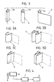
- the diaphragm 6 is constituted by a curtain - like element having a substantially rectangular shape, which can be wound on one side (figure 3) or bent in various manners (see the variants of figures 3A, 3B, 3C, 3D).
- the movement of the diaphragm 6 is controlled by an electric motor which is not shown in figure 3, but is designated by 7 in the block diagram of figure 4.
- the details of construction of the electric motor controlling the diaphragm 6 and the way by which it is mounted within the head-lamp are not shown herein, since they can be provided in any known way, and since the deletion of these details from the drawings renders the latter simpler and easier to understand.
- the electric motor 7 which controls the diaphragm 6 is controlled by an electronic control unit 8 which receives a plurality of signals 9 from sensor means sensing the travel and environment conditions of the motor-vehicle.
- an optical element 10 defining a series of lens sectors which are "uncovered” and thus activated, as a function of the opening degree of the diaphragm 6.
- the lens sectors of the element 10 are progressively activated to give rise to a number of additional light beams which added to the basic pattern give rise to an overall light beam coming out of the head-lamp having the more appropriate features for any condition of use.
- the basic pattern B is added with two distinct areas C, as shown in the figure.
- the two areas D are activated, whereas pattern E is generated for driving on a highway.
- the elevated illumination pattern F can be generated, for example for reading elevated street signals.
- the area G is activated instead when a glaring beam has to be obtained.
- Areas L and R are activated for illuminating the road in a curve to the left or the right, respectively, whereas the sum of the two areas L and R is activated when an anti-fog illumination is wished.
- the head-lamp had a dimension of 130 mm in the vertical direction and 112 mm in the horizontal direction, with a diaphragm which in the fully closed condition occupied an area of 36 mm (horizontally) x 30 mm (vertically).
- the diaphragm 6 had an elliptical section of 38 mm x 32 mm and in another variant a circular section with a radius of 36 mm.
- the signals 9 sent to the electronic control unit 8 may come from sensors of various type, such as a sensor of the motor-vehicle steering angle, a speed sensor, a GPS receiver, and sensors of the environment and light conditions. Additionally or alternatively, a video camera may be used, located on board the motor-vehicle and adapted to the detect both the environment conditions and the conditions of the road on which the motor-vehicle travels.
Landscapes
- Engineering & Computer Science (AREA)
- General Engineering & Computer Science (AREA)
- Lighting Device Outwards From Vehicle And Optical Signal (AREA)
Description
- The present invention relates to motor-vehicle head-lamps, of the type indicated in the pre-characterizing portion of claim 1. A head-lamp of this type is known from DE-A-196 42 467.
- In particular, the invention relates to an adaptive type head-lamp, i.e. a head-lamp adapted to generate an output light beam whose pattern can be varied as a function of the travel conditions of the motor-vehicle (steering angle, speed, etc.) and the environment and light conditions, as well as the road conditions.
- The object of the present invention is that of providing an adaptive head-lamp which on one hand provides an optimized pattern in any condition of use, and on the other hand has a relatively simple structure, with a very reduced bulk and a relatively low cost.
- In view of achieving this object, the invention provides a head-lamp having the features of claim 1.
- Preferably the above mentioned central area where the diaphragm is located is slightly offset downwardly, below the horizontal line passing through the centre of the reflector.
- According to a further feature of the invention, motor means are provided for driving movement of diaphragm between its fully closed position and its fully opened position and electronic control means for controlling said motor means are also provided, which receive signals from sensor means for sensing the travel and environment conditions and control the motor means as a function of said signals.
- The above mentioned sensor means may comprise for instance a sensor of the motor-vehicle steering angle, a speed sensor, a light sensor, a GPS receiver, or also a video camera located on board the vehicle having the function of monitoring both the environment conditions and the conditions of the road on which the motor-vehicle travels.
- In the preferred embodiment of the invention, the light source is constituted by a discharge lamp, such as of the D2S of D2R type. The transparent element is preferably a totally transparent element, with no lenses or prisms.
- In the above mentioned preferred embodiment, the diaphragm is constituted by a substantially rectangular element made of a metal sheet which can be wound or bent.
- Further features and advantages of the invention will become apparent from the description which follows with reference to the annexed drawings, given purely by way of non limiting example, in which:
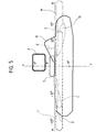
- figure 1 is a cross-sectional of diagrammatic view of a head-lamp according to the invention,
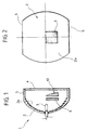
- figure 2 is a front-view of the head-lamp of figure 1,
- figures 3, 3A, 3B, 3C, 3D show different embodiments of the diaphragm forming part of the head-lamp according to the invention,
- figure 4 is a block diagram which shows the principle of operation of the diaphragm,
- and figure 5 is a diagram showing the various light patterns which can be obtained by the head-lamp according to the invention.
-
- With reference to the drawings, numeral 1 generally designates a motor-vehicle head-lamp, comprising a reflector 2 associated with a
light source 3, preferably a discharge lamp, such as of the type marketed under the codes D2S or D2R. A transparent element 4 which is totally transparent, i. e. has no lenses or prisms, is located at the front of the reflector 2. In the example shown, the reflector 2 has twoplanar walls 5, located at the top and at the bottom, having absorbing features. The materials chosen for reflector 2 and transparent element 4 may be those which are used traditionally in the head-lamps of this type. - Between the transparent element 4 and the reflector 2 there is placed a
diaphragm 6 which can be adjusted continuously between a fully closed position (shown in figure 2 and the left-hand part of figure 3) and a fully opened position (shown in the right-hand part of figure 3). Whendiaphragm 6 is in the fully closed condition, it occupies an area corresponding to a substantially central area of the reflector 2, as shown in figure 2. The reflector 2 has anannular area 2a surrounding said central area and having a surface which is shaped so as to generate a light beam coming out of the head-lamp having a basic predetermined pattern, of the "low beam" type. - Figure 5 shows the pattern which can be obtained with the head-lamp according to the invention in a plane orthogonal to the optical axis of the head-lamp located at a distance of 25 meters therefrom. In this figure, axes H and V respectively designate the horizontal and vertical directions, whereas the various lines indicate the profiles of the area illuminated by the head-lamp in the different conditions of use. The basic beam generated by the
annular area 2a of reflector 2 is that which gives rise to the pattern designated by line B, of the "low beam" or "cross-beam" type, having features defined by the regulations or more specifically by the car manufacturers. - In the embodiment shown in the drawings, the
diaphragm 6 is constituted by a curtain - like element having a substantially rectangular shape, which can be wound on one side (figure 3) or bent in various manners (see the variants of figures 3A, 3B, 3C, 3D). The movement of thediaphragm 6 is controlled by an electric motor which is not shown in figure 3, but is designated by 7 in the block diagram of figure 4. The details of construction of the electric motor controlling thediaphragm 6 and the way by which it is mounted within the head-lamp are not shown herein, since they can be provided in any known way, and since the deletion of these details from the drawings renders the latter simpler and easier to understand. With reference to figure 4, the electric motor 7 which controls thediaphragm 6 is controlled by anelectronic control unit 8 which receives a plurality of signals 9 from sensor means sensing the travel and environment conditions of the motor-vehicle. - Also with reference to figure 1, in front of the
diaphragm 6, i. e. between thediaphragm 6 and the transparent element 4 (or alternatively at the rear of the diaphragm) there is located anoptical element 10 defining a series of lens sectors which are "uncovered" and thus activated, as a function of the opening degree of thediaphragm 6. When thediaphragm 6 is fully closed, none of these sectors is active, so that the head-lamp only generates the basic pattern B of figure 5. When the diaphragm is opened, the lens sectors of theelement 10 are progressively activated to give rise to a number of additional light beams which added to the basic pattern give rise to an overall light beam coming out of the head-lamp having the more appropriate features for any condition of use. - Thus, for example, with reference to figure 5, in the case of activation for driving in town, the basic pattern B is added with two distinct areas C, as shown in the figure. For driving out of town, the two areas D are activated, whereas pattern E is generated for driving on a highway. If desired, the elevated illumination pattern F can be generated, for example for reading elevated street signals. The area G is activated instead when a glaring beam has to be obtained. Areas L and R are activated for illuminating the road in a curve to the left or the right, respectively, whereas the sum of the two areas L and R is activated when an anti-fog illumination is wished.
- In an embodiment of the device according to the invention, the head-lamp had a dimension of 130 mm in the vertical direction and 112 mm in the horizontal direction, with a diaphragm which in the fully closed condition occupied an area of 36 mm (horizontally) x 30 mm (vertically). In a variant, the
diaphragm 6 had an elliptical section of 38 mm x 32 mm and in another variant a circular section with a radius of 36 mm. - As already indicated in the foregoing, the signals 9 sent to the
electronic control unit 8 may come from sensors of various type, such as a sensor of the motor-vehicle steering angle, a speed sensor, a GPS receiver, and sensors of the environment and light conditions. Additionally or alternatively, a video camera may be used, located on board the motor-vehicle and adapted to the detect both the environment conditions and the conditions of the road on which the motor-vehicle travels. - Naturally, while the principle of the invention remains the same, the details of construction and the embodiments may widely vary with respect to what has been described and illustrated purely by way of example, without departing from the scope of the present invention.
- In particular, it is possible to provide for many diaphragms adapted to cooperate with each other in order to "uncover" and thus activate any portion of the
optical element 10.
Claims (7)
- Motor-vehicle head-lamp, comprising a light source (3), a reflector (2) associated with the source (3), and a transparent element (4) located in front of the reflector (2), wherein:between the reflector (2) and the transparent element (4) there is located at least one diaphragm (6), andin front or at the rear of the diaphragm (6) there is located an optical element (10), said head-lamp being characterized in that:said diaphragm (6) can be adjusted between a fully opened position and a fully closed position,said diaphragm (6) occupies an area corresponding to a substantially central area of the reflector (2) in the fully closed position of said diaphragm (6),said reflector (2) has an annular area, surrounding said central area, having a surface which is shaped so as to generate a light beam coming out of the head-lamp having a predetermined basic pattern B, andsaid optical element (10) is constituted by a plurality of lens sectors which are uncovered in a variable manner as a function of the opening degree of the diaphragm (6) and are shaped so that they give rise to a plurality of additional light beams, which may be selected by means of the diaphragm (6) so as to generate an overall pattern which is different for each condition of use.
- Head-lamp according to claim 1, characterized in that motor means (7) are provided for driving movement of the diaphragm (6) between its fully closed position and its fully opened position, and electronic control means (8) are provided for controlling said motor means (7), said control means (8) for receiving signals (9) from said sensor means of the motor-vehicle travel conditions and the environment conditions and controlling said motor means (7) as a function of said signals.
- Head-lamp according to claim 2, characterized in that said sensor means comprises one or more sensors chosen among: a sensor of the motor-vehicle steering angle, a speed sensor, a sensor of environment light, a GPS receiver.
- Head-lamp according to claim 2, characterized in that said sensor means comprises a video camera located on board the motor-vehicle and adapted to detect the environment conditions and the conditions of the road on which the motor-vehicle travel.
- Head-lamp according to claim 1, characterized in that said transparent element (4) has a totally transparent surface having no prisms or lenses.
- Head-lamp according to claim 1, characterized in that said diaphragm (6) is made by at least one sheet element having a substantially rectangular shape which can be wound or bent.
- Head-lamp according to claim 1, characterized in that said diaphragm (6) is shaped so as to selectively activate any portion of said optical element in each partially opened condition thereof.
Priority Applications (2)
| Application Number | Priority Date | Filing Date | Title |
|---|---|---|---|
| DE69927006T DE69927006T2 (en) | 1999-07-16 | 1999-07-16 | Adaptive motor vehicle headlight with an adjustable, central aperture |
| EP99830455A EP1069374B1 (en) | 1999-07-16 | 1999-07-16 | Motor-vehicle adaptive head-lamp having a central adjustable diaphragm |
Applications Claiming Priority (1)
| Application Number | Priority Date | Filing Date | Title |
|---|---|---|---|
| EP99830455A EP1069374B1 (en) | 1999-07-16 | 1999-07-16 | Motor-vehicle adaptive head-lamp having a central adjustable diaphragm |
Publications (2)
| Publication Number | Publication Date |
|---|---|
| EP1069374A1 EP1069374A1 (en) | 2001-01-17 |
| EP1069374B1 true EP1069374B1 (en) | 2005-08-31 |
Family
ID=8243504
Family Applications (1)
| Application Number | Title | Priority Date | Filing Date |
|---|---|---|---|
| EP99830455A Expired - Lifetime EP1069374B1 (en) | 1999-07-16 | 1999-07-16 | Motor-vehicle adaptive head-lamp having a central adjustable diaphragm |
Country Status (2)
| Country | Link |
|---|---|
| EP (1) | EP1069374B1 (en) |
| DE (1) | DE69927006T2 (en) |
Family Cites Families (3)
| Publication number | Priority date | Publication date | Assignee | Title |
|---|---|---|---|---|
| FR2699259B1 (en) * | 1992-12-14 | 1995-03-03 | Valeo Vision | Motor vehicle headlamp comprising means for generating two different beams from the same source and from the same mirror. |
| DE4435507A1 (en) * | 1994-10-04 | 1996-04-11 | Bosch Gmbh Robert | Low beam and high beam headlights for vehicles |
| DE19642467B4 (en) * | 1996-10-15 | 2010-04-08 | Automotive Lighting Reutlingen Gmbh | Headlight system for vehicles for emitting a variable light beam |
-
1999
- 1999-07-16 EP EP99830455A patent/EP1069374B1/en not_active Expired - Lifetime
- 1999-07-16 DE DE69927006T patent/DE69927006T2/en not_active Expired - Fee Related
Also Published As
| Publication number | Publication date |
|---|---|
| EP1069374A1 (en) | 2001-01-17 |
| DE69927006T2 (en) | 2006-06-22 |
| DE69927006D1 (en) | 2005-10-06 |
Similar Documents
| Publication | Publication Date | Title |
|---|---|---|
| US4967319A (en) | Headlight apparatus for automotive vehicle | |
| US7364333B2 (en) | Vehicle headlight system with variable beam shape | |
| US5567032A (en) | Illuminating device for vehicles | |
| JP3163889U (en) | An optical sensor device mounted on a vehicle for driving assistance and / or for automatically operating a system provided in the vehicle | |
| US5379196A (en) | Projection headlamp for vehicles | |
| US6467940B2 (en) | Headlight for vehicle operating in accordance with projection principle and illumination device with at least one such headlight | |
| US8465187B2 (en) | Light module for a motor vehicle headlamp | |
| EP0591566B1 (en) | Headlamp for motor vehicles | |
| KR101794022B1 (en) | Method for controlling a headlight assembly for a vehicle and headlight assembly therefor | |
| EP2281718B1 (en) | Light distribution control system for automotive headlamp | |
| WO2014151640A1 (en) | Multi-pattern headlamp assembly and system | |
| EP3043108A1 (en) | Vehicular lighting system | |
| KR20220056169A (en) | Apparatus for controlling headlamp of vehicle | |
| US6227691B1 (en) | Headlight arrangement for motor vehicle | |
| KR100726106B1 (en) | Photosensitive detection unit, in particular for automatic connection of lighting equipment | |
| JP5470157B2 (en) | VEHICLE LIGHT SYSTEM, CONTROL DEVICE, VEHICLE LIGHT, AND CONTROL METHOD FOR VEHICLE LIGHT | |
| EP0999407A2 (en) | Double headlamp adaptive device for motor-vehicles, with microlens matrices | |
| JP2005067294A (en) | Headlamp control system | |
| EP1069374B1 (en) | Motor-vehicle adaptive head-lamp having a central adjustable diaphragm | |
| EP1125792A2 (en) | Lamp for automobile | |
| JP2000294016A (en) | HEADLIGHT FOR VEHICLE FOR EMITTING VARIABLE FLUX AND HEADLIGHT DEVICE HAVING AT LEAST TWO HEADLIGHTS | |
| EP0999408A2 (en) | Double headlamp adaptive lighting device for motor-vehicles, having a variable diaphragm | |
| JP5539784B2 (en) | VEHICLE LIGHT SYSTEM, CONTROL DEVICE, AND VEHICLE LIGHT | |
| EP1054211B1 (en) | Adaptive head-lamp for motor-vehicles | |
| CN112140983A (en) | Method for controlling cut-off line, vehicle lamp and vehicle |
Legal Events
| Date | Code | Title | Description |
|---|---|---|---|
| PUAI | Public reference made under article 153(3) epc to a published international application that has entered the european phase |
Free format text: ORIGINAL CODE: 0009012 |
|
| 17P | Request for examination filed |
Effective date: 20000529 |
|
| AK | Designated contracting states |
Kind code of ref document: A1 Designated state(s): DE ES FR GB |
|
| AX | Request for extension of the european patent |
Free format text: AL;LT;LV;MK;RO;SI |
|
| AKX | Designation fees paid |
Free format text: DE ES FR GB |
|
| 17Q | First examination report despatched |
Effective date: 20040727 |
|
| GRAP | Despatch of communication of intention to grant a patent |
Free format text: ORIGINAL CODE: EPIDOSNIGR1 |
|
| GRAS | Grant fee paid |
Free format text: ORIGINAL CODE: EPIDOSNIGR3 |
|
| GRAA | (expected) grant |
Free format text: ORIGINAL CODE: 0009210 |
|
| AK | Designated contracting states |
Kind code of ref document: B1 Designated state(s): DE ES FR GB |
|
| REG | Reference to a national code |
Ref country code: GB Ref legal event code: FG4D |
|
| REF | Corresponds to: |
Ref document number: 69927006 Country of ref document: DE Date of ref document: 20051006 Kind code of ref document: P |
|
| PG25 | Lapsed in a contracting state [announced via postgrant information from national office to epo] |
Ref country code: ES Free format text: LAPSE BECAUSE OF FAILURE TO SUBMIT A TRANSLATION OF THE DESCRIPTION OR TO PAY THE FEE WITHIN THE PRESCRIBED TIME-LIMIT Effective date: 20051212 |
|
| ET | Fr: translation filed | ||
| PLBE | No opposition filed within time limit |
Free format text: ORIGINAL CODE: 0009261 |
|
| STAA | Information on the status of an ep patent application or granted ep patent |
Free format text: STATUS: NO OPPOSITION FILED WITHIN TIME LIMIT |
|
| PGFP | Annual fee paid to national office [announced via postgrant information from national office to epo] |
Ref country code: DE Payment date: 20060713 Year of fee payment: 8 |
|
| PG25 | Lapsed in a contracting state [announced via postgrant information from national office to epo] |
Ref country code: GB Free format text: LAPSE BECAUSE OF NON-PAYMENT OF DUE FEES Effective date: 20060716 |
|
| 26N | No opposition filed |
Effective date: 20060601 |
|
| GBPC | Gb: european patent ceased through non-payment of renewal fee |
Effective date: 20060716 |
|
| PG25 | Lapsed in a contracting state [announced via postgrant information from national office to epo] |
Ref country code: DE Free format text: LAPSE BECAUSE OF NON-PAYMENT OF DUE FEES Effective date: 20080201 |
|
| REG | Reference to a national code |
Ref country code: FR Ref legal event code: PLFP Year of fee payment: 18 |
|
| REG | Reference to a national code |
Ref country code: FR Ref legal event code: PLFP Year of fee payment: 19 |
|
| REG | Reference to a national code |
Ref country code: FR Ref legal event code: PLFP Year of fee payment: 20 |
|
| PGFP | Annual fee paid to national office [announced via postgrant information from national office to epo] |
Ref country code: FR Payment date: 20180621 Year of fee payment: 20 |