EP1069374B1 - Projecteur adaptif pour véhicule automobile avec un cache central ajustable - Google Patents
Projecteur adaptif pour véhicule automobile avec un cache central ajustable Download PDFInfo
- Publication number
- EP1069374B1 EP1069374B1 EP99830455A EP99830455A EP1069374B1 EP 1069374 B1 EP1069374 B1 EP 1069374B1 EP 99830455 A EP99830455 A EP 99830455A EP 99830455 A EP99830455 A EP 99830455A EP 1069374 B1 EP1069374 B1 EP 1069374B1
- Authority
- EP
- European Patent Office
- Prior art keywords
- diaphragm
- head
- motor
- lamp
- reflector
- Prior art date
- Legal status (The legal status is an assumption and is not a legal conclusion. Google has not performed a legal analysis and makes no representation as to the accuracy of the status listed.)
- Expired - Lifetime
Links
- 230000003044 adaptive effect Effects 0.000 title description 3
- 230000003287 optical effect Effects 0.000 claims description 6
- 238000010586 diagram Methods 0.000 description 3
- 238000010276 construction Methods 0.000 description 2
- 238000005286 illumination Methods 0.000 description 2
- 230000004913 activation Effects 0.000 description 1
- 238000012217 deletion Methods 0.000 description 1
- 230000037430 deletion Effects 0.000 description 1
- 239000000463 material Substances 0.000 description 1
- 239000002184 metal Substances 0.000 description 1
- 238000012544 monitoring process Methods 0.000 description 1
Images
Classifications
-
- F—MECHANICAL ENGINEERING; LIGHTING; HEATING; WEAPONS; BLASTING
- F21—LIGHTING
- F21S—NON-PORTABLE LIGHTING DEVICES; SYSTEMS THEREOF; VEHICLE LIGHTING DEVICES SPECIALLY ADAPTED FOR VEHICLE EXTERIORS
- F21S41/00—Illuminating devices specially adapted for vehicle exteriors, e.g. headlamps
- F21S41/60—Illuminating devices specially adapted for vehicle exteriors, e.g. headlamps characterised by a variable light distribution
- F21S41/68—Illuminating devices specially adapted for vehicle exteriors, e.g. headlamps characterised by a variable light distribution by acting on screens
- F21S41/683—Illuminating devices specially adapted for vehicle exteriors, e.g. headlamps characterised by a variable light distribution by acting on screens by moving screens
- F21S41/692—Shields, i.e. screens not creating an image meant to be projected
-
- F—MECHANICAL ENGINEERING; LIGHTING; HEATING; WEAPONS; BLASTING
- F21—LIGHTING
- F21S—NON-PORTABLE LIGHTING DEVICES; SYSTEMS THEREOF; VEHICLE LIGHTING DEVICES SPECIALLY ADAPTED FOR VEHICLE EXTERIORS
- F21S41/00—Illuminating devices specially adapted for vehicle exteriors, e.g. headlamps
- F21S41/20—Illuminating devices specially adapted for vehicle exteriors, e.g. headlamps characterised by refractors, transparent cover plates, light guides or filters
- F21S41/28—Cover glass
Definitions
- the present invention relates to motor-vehicle head-lamps, of the type indicated in the pre-characterizing portion of claim 1.
- a head-lamp of this type is known from DE-A-196 42 467.
- the invention relates to an adaptive type head-lamp, i.e. a head-lamp adapted to generate an output light beam whose pattern can be varied as a function of the travel conditions of the motor-vehicle (steering angle, speed, etc.) and the environment and light conditions, as well as the road conditions.
- an adaptive type head-lamp i.e. a head-lamp adapted to generate an output light beam whose pattern can be varied as a function of the travel conditions of the motor-vehicle (steering angle, speed, etc.) and the environment and light conditions, as well as the road conditions.
- the object of the present invention is that of providing an adaptive head-lamp which on one hand provides an optimized pattern in any condition of use, and on the other hand has a relatively simple structure, with a very reduced bulk and a relatively low cost.
- the invention provides a head-lamp having the features of claim 1.
- the above mentioned central area where the diaphragm is located is slightly offset downwardly, below the horizontal line passing through the centre of the reflector.
- motor means are provided for driving movement of diaphragm between its fully closed position and its fully opened position and electronic control means for controlling said motor means are also provided, which receive signals from sensor means for sensing the travel and environment conditions and control the motor means as a function of said signals.
- the above mentioned sensor means may comprise for instance a sensor of the motor-vehicle steering angle, a speed sensor, a light sensor, a GPS receiver, or also a video camera located on board the vehicle having the function of monitoring both the environment conditions and the conditions of the road on which the motor-vehicle travels.
- the light source is constituted by a discharge lamp, such as of the D2S of D2R type.
- the transparent element is preferably a totally transparent element, with no lenses or prisms.
- the diaphragm is constituted by a substantially rectangular element made of a metal sheet which can be wound or bent.
- numeral 1 generally designates a motor-vehicle head-lamp, comprising a reflector 2 associated with a light source 3, preferably a discharge lamp, such as of the type marketed under the codes D2S or D2R.
- a transparent element 4 which is totally transparent, i. e. has no lenses or prisms, is located at the front of the reflector 2.
- the reflector 2 has two planar walls 5, located at the top and at the bottom, having absorbing features.
- the materials chosen for reflector 2 and transparent element 4 may be those which are used traditionally in the head-lamps of this type.
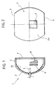
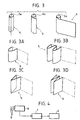
- diaphragm 6 which can be adjusted continuously between a fully closed position (shown in figure 2 and the left-hand part of figure 3) and a fully opened position (shown in the right-hand part of figure 3).
- diaphragm 6 When diaphragm 6 is in the fully closed condition, it occupies an area corresponding to a substantially central area of the reflector 2, as shown in figure 2.
- the reflector 2 has an annular area 2a surrounding said central area and having a surface which is shaped so as to generate a light beam coming out of the head-lamp having a basic predetermined pattern, of the "low beam" type.
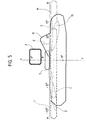
- Figure 5 shows the pattern which can be obtained with the head-lamp according to the invention in a plane orthogonal to the optical axis of the head-lamp located at a distance of 25 meters therefrom.
- axes H and V respectively designate the horizontal and vertical directions, whereas the various lines indicate the profiles of the area illuminated by the head-lamp in the different conditions of use.
- the basic beam generated by the annular area 2a of reflector 2 is that which gives rise to the pattern designated by line B, of the "low beam” or "cross-beam” type, having features defined by the regulations or more specifically by the car manufacturers.
- the diaphragm 6 is constituted by a curtain - like element having a substantially rectangular shape, which can be wound on one side (figure 3) or bent in various manners (see the variants of figures 3A, 3B, 3C, 3D).
- the movement of the diaphragm 6 is controlled by an electric motor which is not shown in figure 3, but is designated by 7 in the block diagram of figure 4.
- the details of construction of the electric motor controlling the diaphragm 6 and the way by which it is mounted within the head-lamp are not shown herein, since they can be provided in any known way, and since the deletion of these details from the drawings renders the latter simpler and easier to understand.
- the electric motor 7 which controls the diaphragm 6 is controlled by an electronic control unit 8 which receives a plurality of signals 9 from sensor means sensing the travel and environment conditions of the motor-vehicle.
- an optical element 10 defining a series of lens sectors which are "uncovered” and thus activated, as a function of the opening degree of the diaphragm 6.
- the lens sectors of the element 10 are progressively activated to give rise to a number of additional light beams which added to the basic pattern give rise to an overall light beam coming out of the head-lamp having the more appropriate features for any condition of use.
- the basic pattern B is added with two distinct areas C, as shown in the figure.
- the two areas D are activated, whereas pattern E is generated for driving on a highway.
- the elevated illumination pattern F can be generated, for example for reading elevated street signals.
- the area G is activated instead when a glaring beam has to be obtained.
- Areas L and R are activated for illuminating the road in a curve to the left or the right, respectively, whereas the sum of the two areas L and R is activated when an anti-fog illumination is wished.
- the head-lamp had a dimension of 130 mm in the vertical direction and 112 mm in the horizontal direction, with a diaphragm which in the fully closed condition occupied an area of 36 mm (horizontally) x 30 mm (vertically).
- the diaphragm 6 had an elliptical section of 38 mm x 32 mm and in another variant a circular section with a radius of 36 mm.
- the signals 9 sent to the electronic control unit 8 may come from sensors of various type, such as a sensor of the motor-vehicle steering angle, a speed sensor, a GPS receiver, and sensors of the environment and light conditions. Additionally or alternatively, a video camera may be used, located on board the motor-vehicle and adapted to the detect both the environment conditions and the conditions of the road on which the motor-vehicle travels.
Landscapes
- Engineering & Computer Science (AREA)
- General Engineering & Computer Science (AREA)
- Lighting Device Outwards From Vehicle And Optical Signal (AREA)
Claims (7)
- Phare pour véhicule automobile, comprenant une source de lumière (3), un réflecteur (2) associé à la source (3), et un élément transparent (4) situé devant le réflecteur (2), et dans lequel :ledit phare étant caractérisé en ce que :au moins un diaphragme (6) est placé entre le réflecteur (2) et l'élément transparent (4) ; etun élément optique (10) est placé devant ou derrière le diaphragme (6),ledit diaphragme (6) peut être réglé entre une position complètement ouverte et une position complètement fermée,ledit diaphragme (6) occupe une zone correspondant à une zone sensiblement centrale du réflecteur (2), dans la position complètement fermée dudit diaphragme (6),ledit réflecteur (2) présente une zone annulaire, entourant ladite zone centrale et ayant une surface qui est conformée de manière à produire un faisceau lumineux, qui sort du phare avec une forme prédéterminée de base B du rayonnement, etledit élément optique (10) est constitué par une pluralité de secteurs dé lentille, qui sont découverts de manière variable en fonction du degré d'ouverture du diaphragme (6) et qui sont conformés de façon à pouvoir engendrer une pluralité de faisceaux lumineux supplémentaires, qui peuvent être sélectionnés au moyen du diaphragme (6) afin de produire une forme globale de rayonnement, qui est différente pour chaque condition d'utilisation.
- Phare selon la revendication 1, caractérisé en ce qu'il est prévu des moyens formant moteur (7) pour commander le mouvement du diaphragme (6) entre sa position complètement fermée et sa position complètement ouverte, et en ce que des moyens de commande électronique (8) sont prévus pour commander lesdits moyens formant moteur (7), lesdits moyens de commande (8) recevant des signaux (9) provenant de moyens de détection des conditions de déplacement du véhicule automobile et des conditions ambiantes, et commandant lesdits moyens formant moteur (7) en fonction desdits signaux.
- Phare selon la revendication 2, caractérisé en ce que lesdits moyens de détection comprennent un ou plusieurs capteurs, choisis parmi : un capteur d'angle de braquage du véhicule automobile, un capteur de vitesse, un capteur de lumière ambiante, un récepteur GPS.
- Phare selon la revendication 2, caractérisé en ce que lesdits moyens de détection comprennent une caméra vidéo, placée à bord du véhicule automobile et propre à détecter les conditions ambiantes et l'état de la route sur laquelle roule le véhicule automobile.
- Phare selon la revendication 1, caractérisé en ce que ledit élément transparent (4) présente une surface totalement transparente, sans prismes ni lentilles.
- Phare selon la revendication 1, caractérisé en ce que ledit diaphragme (6) consiste en au moins un élément en feuille, présentant une forme sensiblement rectangulaire, et qui peut être enroulé ou plié.
- Phare selon la revendication 1, caractérisé en ce que ledit diaphragme (6) est conformé de manière à mettre sélectivement en fonction une partie quelconque dudit élément optique, dans chacun de ses états partiellement ouverts.
Priority Applications (2)
| Application Number | Priority Date | Filing Date | Title |
|---|---|---|---|
| DE69927006T DE69927006T2 (de) | 1999-07-16 | 1999-07-16 | Adaptiver Kraftfahrzeug-Scheinwerfer mit einer verstellbaren, zentralen Blende |
| EP99830455A EP1069374B1 (fr) | 1999-07-16 | 1999-07-16 | Projecteur adaptif pour véhicule automobile avec un cache central ajustable |
Applications Claiming Priority (1)
| Application Number | Priority Date | Filing Date | Title |
|---|---|---|---|
| EP99830455A EP1069374B1 (fr) | 1999-07-16 | 1999-07-16 | Projecteur adaptif pour véhicule automobile avec un cache central ajustable |
Publications (2)
| Publication Number | Publication Date |
|---|---|
| EP1069374A1 EP1069374A1 (fr) | 2001-01-17 |
| EP1069374B1 true EP1069374B1 (fr) | 2005-08-31 |
Family
ID=8243504
Family Applications (1)
| Application Number | Title | Priority Date | Filing Date |
|---|---|---|---|
| EP99830455A Expired - Lifetime EP1069374B1 (fr) | 1999-07-16 | 1999-07-16 | Projecteur adaptif pour véhicule automobile avec un cache central ajustable |
Country Status (2)
| Country | Link |
|---|---|
| EP (1) | EP1069374B1 (fr) |
| DE (1) | DE69927006T2 (fr) |
Family Cites Families (3)
| Publication number | Priority date | Publication date | Assignee | Title |
|---|---|---|---|---|
| FR2699259B1 (fr) * | 1992-12-14 | 1995-03-03 | Valeo Vision | Projecteur de véhicule automobile comportant des moyens pour engendrer deux faisceaux différents à partir d'une même source et d'un même miroir. |
| DE4435507A1 (de) * | 1994-10-04 | 1996-04-11 | Bosch Gmbh Robert | Scheinwerfer für Abblendlicht und Fernlicht für Fahrzeuge |
| DE19642467B4 (de) * | 1996-10-15 | 2010-04-08 | Automotive Lighting Reutlingen Gmbh | Scheinwerferanlage für Fahrzeuge zur Aussendung eines veränderlichen Lichtbündels |
-
1999
- 1999-07-16 EP EP99830455A patent/EP1069374B1/fr not_active Expired - Lifetime
- 1999-07-16 DE DE69927006T patent/DE69927006T2/de not_active Expired - Fee Related
Also Published As
| Publication number | Publication date |
|---|---|
| EP1069374A1 (fr) | 2001-01-17 |
| DE69927006T2 (de) | 2006-06-22 |
| DE69927006D1 (de) | 2005-10-06 |
Similar Documents
| Publication | Publication Date | Title |
|---|---|---|
| US4967319A (en) | Headlight apparatus for automotive vehicle | |
| US7364333B2 (en) | Vehicle headlight system with variable beam shape | |
| US5567032A (en) | Illuminating device for vehicles | |
| JP3163889U (ja) | 運転における補助のための、及び/又は自動車に設けられたシステムを自動的に作動させるための、自動車に搭載される光センサデバイス | |
| US5379196A (en) | Projection headlamp for vehicles | |
| US6467940B2 (en) | Headlight for vehicle operating in accordance with projection principle and illumination device with at least one such headlight | |
| US8465187B2 (en) | Light module for a motor vehicle headlamp | |
| EP0591566B1 (fr) | Phare pour véhicule automobile | |
| KR101794022B1 (ko) | 차량용 전조등 어셈블리의 제어 방법 및 그를 위한 전조등 어셈블리 | |
| EP2281718B1 (fr) | Système de contrôle de la distribution lumineuse de phares de voiture | |
| WO2014151640A1 (fr) | Ensemble phare à plusieurs motifs et système | |
| EP3043108A1 (fr) | Système d'éclairage de véhicule | |
| KR20220056169A (ko) | 차량의 헤드램프 제어장치 | |
| US6227691B1 (en) | Headlight arrangement for motor vehicle | |
| KR100726106B1 (ko) | 감광 센서 유닛 | |
| JP5470157B2 (ja) | 車両用灯具システム、制御装置、車両用灯具、および車両用灯具の制御方法 | |
| EP0999407A2 (fr) | Phare adaptatif pour véhicules automobiles avec matrices de microlentilles | |
| JP2005067294A (ja) | ヘッドランプ制御システム | |
| EP1069374B1 (fr) | Projecteur adaptif pour véhicule automobile avec un cache central ajustable | |
| EP1125792A2 (fr) | Phare de véhicule | |
| JP2000294016A (ja) | 可変な光束を放射するための、車両用の前照灯及び、少なくとも2つの前照灯を有する前照灯装置 | |
| EP0999408A2 (fr) | Projecteur de véhicule automobile adaptatif comportant un diaphragme réglable | |
| JP5539784B2 (ja) | 車両用灯具システム、制御装置、および車両用灯具 | |
| EP1054211B1 (fr) | Projecteur adaptatif pour véhicules automobiles | |
| CN112140983A (zh) | 控制明暗截止线的方法、车灯和车辆 |
Legal Events
| Date | Code | Title | Description |
|---|---|---|---|
| PUAI | Public reference made under article 153(3) epc to a published international application that has entered the european phase |
Free format text: ORIGINAL CODE: 0009012 |
|
| 17P | Request for examination filed |
Effective date: 20000529 |
|
| AK | Designated contracting states |
Kind code of ref document: A1 Designated state(s): DE ES FR GB |
|
| AX | Request for extension of the european patent |
Free format text: AL;LT;LV;MK;RO;SI |
|
| AKX | Designation fees paid |
Free format text: DE ES FR GB |
|
| 17Q | First examination report despatched |
Effective date: 20040727 |
|
| GRAP | Despatch of communication of intention to grant a patent |
Free format text: ORIGINAL CODE: EPIDOSNIGR1 |
|
| GRAS | Grant fee paid |
Free format text: ORIGINAL CODE: EPIDOSNIGR3 |
|
| GRAA | (expected) grant |
Free format text: ORIGINAL CODE: 0009210 |
|
| AK | Designated contracting states |
Kind code of ref document: B1 Designated state(s): DE ES FR GB |
|
| REG | Reference to a national code |
Ref country code: GB Ref legal event code: FG4D |
|
| REF | Corresponds to: |
Ref document number: 69927006 Country of ref document: DE Date of ref document: 20051006 Kind code of ref document: P |
|
| PG25 | Lapsed in a contracting state [announced via postgrant information from national office to epo] |
Ref country code: ES Free format text: LAPSE BECAUSE OF FAILURE TO SUBMIT A TRANSLATION OF THE DESCRIPTION OR TO PAY THE FEE WITHIN THE PRESCRIBED TIME-LIMIT Effective date: 20051212 |
|
| ET | Fr: translation filed | ||
| PLBE | No opposition filed within time limit |
Free format text: ORIGINAL CODE: 0009261 |
|
| STAA | Information on the status of an ep patent application or granted ep patent |
Free format text: STATUS: NO OPPOSITION FILED WITHIN TIME LIMIT |
|
| PGFP | Annual fee paid to national office [announced via postgrant information from national office to epo] |
Ref country code: DE Payment date: 20060713 Year of fee payment: 8 |
|
| PG25 | Lapsed in a contracting state [announced via postgrant information from national office to epo] |
Ref country code: GB Free format text: LAPSE BECAUSE OF NON-PAYMENT OF DUE FEES Effective date: 20060716 |
|
| 26N | No opposition filed |
Effective date: 20060601 |
|
| GBPC | Gb: european patent ceased through non-payment of renewal fee |
Effective date: 20060716 |
|
| PG25 | Lapsed in a contracting state [announced via postgrant information from national office to epo] |
Ref country code: DE Free format text: LAPSE BECAUSE OF NON-PAYMENT OF DUE FEES Effective date: 20080201 |
|
| REG | Reference to a national code |
Ref country code: FR Ref legal event code: PLFP Year of fee payment: 18 |
|
| REG | Reference to a national code |
Ref country code: FR Ref legal event code: PLFP Year of fee payment: 19 |
|
| REG | Reference to a national code |
Ref country code: FR Ref legal event code: PLFP Year of fee payment: 20 |
|
| PGFP | Annual fee paid to national office [announced via postgrant information from national office to epo] |
Ref country code: FR Payment date: 20180621 Year of fee payment: 20 |