EP0705488B1 - Antenne - Google Patents
Antenne Download PDFInfo
- Publication number
- EP0705488B1 EP0705488B1 EP95915275A EP95915275A EP0705488B1 EP 0705488 B1 EP0705488 B1 EP 0705488B1 EP 95915275 A EP95915275 A EP 95915275A EP 95915275 A EP95915275 A EP 95915275A EP 0705488 B1 EP0705488 B1 EP 0705488B1
- Authority
- EP
- European Patent Office
- Prior art keywords
- layers
- antenna
- axis
- rear end
- electromagnetic radiation
- Prior art date
- Legal status (The legal status is an assumption and is not a legal conclusion. Google has not performed a legal analysis and makes no representation as to the accuracy of the status listed.)
- Expired - Lifetime
Links
- 230000005670 electromagnetic radiation Effects 0.000 claims description 30
- 230000007704 transition Effects 0.000 claims description 24
- 238000000926 separation method Methods 0.000 claims description 22
- 239000003989 dielectric material Substances 0.000 claims description 20
- 239000000463 material Substances 0.000 claims description 13
- 230000005540 biological transmission Effects 0.000 claims description 9
- -1 polyethylene Polymers 0.000 claims description 7
- 229920000573 polyethylene Polymers 0.000 claims description 7
- 239000004698 Polyethylene Substances 0.000 claims description 6
- 239000004794 expanded polystyrene Substances 0.000 claims description 3
- 229920002635 polyurethane Polymers 0.000 claims description 3
- 239000004814 polyurethane Substances 0.000 claims description 3
- 230000001419 dependent effect Effects 0.000 claims description 2
- 238000010276 construction Methods 0.000 description 4
- 230000000694 effects Effects 0.000 description 4
- 230000008901 benefit Effects 0.000 description 3
- 230000005855 radiation Effects 0.000 description 3
- 230000004323 axial length Effects 0.000 description 2
- 230000008878 coupling Effects 0.000 description 2
- 238000010168 coupling process Methods 0.000 description 2
- 238000005859 coupling reaction Methods 0.000 description 2
- 230000005684 electric field Effects 0.000 description 2
- NCGICGYLBXGBGN-UHFFFAOYSA-N 3-morpholin-4-yl-1-oxa-3-azonia-2-azanidacyclopent-3-en-5-imine;hydrochloride Chemical compound Cl.[N-]1OC(=N)C=[N+]1N1CCOCC1 NCGICGYLBXGBGN-UHFFFAOYSA-N 0.000 description 1
- 230000015572 biosynthetic process Effects 0.000 description 1
- 230000002301 combined effect Effects 0.000 description 1
- 238000010586 diagram Methods 0.000 description 1
- 230000008030 elimination Effects 0.000 description 1
- 238000003379 elimination reaction Methods 0.000 description 1
- 238000004519 manufacturing process Methods 0.000 description 1
- 230000004048 modification Effects 0.000 description 1
- 238000012986 modification Methods 0.000 description 1
- 230000001902 propagating effect Effects 0.000 description 1
- 230000007480 spreading Effects 0.000 description 1
Images


Classifications
-
- H—ELECTRICITY
- H01—ELECTRIC ELEMENTS
- H01Q—ANTENNAS, i.e. RADIO AERIALS
- H01Q13/00—Waveguide horns or mouths; Slot antennas; Leaky-waveguide antennas; Equivalent structures causing radiation along the transmission path of a guided wave
- H01Q13/02—Waveguide horns
- H01Q13/0233—Horns fed by a slotted waveguide array
-
- H—ELECTRICITY
- H01—ELECTRIC ELEMENTS
- H01Q—ANTENNAS, i.e. RADIO AERIALS
- H01Q19/00—Combinations of primary active antenna elements and units with secondary devices, e.g. with quasi-optical devices, for giving the antenna a desired directional characteristic
- H01Q19/06—Combinations of primary active antenna elements and units with secondary devices, e.g. with quasi-optical devices, for giving the antenna a desired directional characteristic using refracting or diffracting devices, e.g. lens
Definitions
- the present invention relates to an antenna for at least one of the transmission and the reception of electromagnetic radiation.
- a linear array antenna comprises a slotted waveguide 1 with slots 1a provided in a side wall coupled to a feedhorn 2. This configuration is termed “broadside fire” because the axis of the main beam is orthogonal to the plane of the aperture generally indicated by reference numeral 3.
- the radiating aperture is along the axial length of the rod and therefore directionality is increased by increasing the length of the aperture, i.e. the length of the polyethylene rod 6 in Figure 2.
- the polyethylene rod 6 is coupled electromagnetically to the radiation provided from a waveguide 4 by a transition element 5.
- the polyethylene forms a "leaky” antenna structure wherein energy "leaking" from the surface of the rod combines constructively in the direction the rod points, thus forming a beam.
- Japanese Patent No. 56-31205 has proposed the use of a hollow "polyrod” shown in Figure 3 comprising a slotted waveguide 7 with slots 7a coupled to a hollow dielectric rod 9 via a transition element 8.
- this arrangement overcomes the weight disadvantage of the "polyrod” arrangement this arrangement still suffers from the disadvantage of requiring a long axial length in order to provide sufficient beam width.
- GB-A-2157082 discloses an antenna with four dielectric layers extending forward from a transition portion. The described arrangement proposes spacings between layers of over half a wavelength.
- the present invention provides an antenna for at least one of the transmission and the reception of electromagnetic radiation along an axis comprising at least four layers formed of dielectric material spaced from one another in a direction perpendicular to said axis, outermost layers being spaced from one another by at least half the wavelength ( ⁇ ) of said electromagnetic radiation, said layers extending generally in the direction of said axis from a rear end to a front end of said layers; a waveguide; and a transition portion adapted to electromagnetically couple said layers directly to said waveguide; a front end of said transition portion being connected to said rear end of said layers, and having a dimension in the direction perpendicular to said axis substantially equal to the spacing between outermost layers at said rear end of said layers; characterised in that the separation of the closest layers is below half the wavelength ( ⁇ ) of the electromagnetic radiation, and in that the shoulders in the beam pattern produced by interference between said outermost layers are reduced because of the increased number of layers which can contribute to interference.
- the invention provides an antenna for at least one of the transmission and the reception of electromagnetic radiation along an axis comprising a plurality of layers formed of dielectric material spaced from one another in a direction perpendicular to said axis, outermost layers being spaced from one another by at least half the wavelength ( ⁇ ) of said electromagnetic radiation, said layers extending generally in the direction of said axis from a rear end to a front end of said layers; a waveguide; and a transition portion adapted to electromagnetically couple said layers directly to said waveguide; a front end of said transition portion being connected to said rear end of said layers, and having a dimension in the direction perpendicular to said axis substantially equal to the spacing between outermost layers at said rear end of said layers; characterised in that there are three said layers only, and in that the shoulders in the beam pattern produced by interference between said outermost layers are reduced because of the increased number of layers which can contribute to interference.
- the invention provides an antenna for at least one of the transmission and the reception of electromagnetic radiation along an axis comprising a plurality of layers formed of dielectric material spaced from one another in a direction perpendicular to said axis, outermost layers being spaced from one another by at least half the wavelength ( ⁇ ) of said electromagnetic radiation, said layers extending generally in the direction of said axis from a rear end to a front end of said layers; a waveguide; and a transition portion connected to said rear end of said layers and adapted to electromagnetically couple said layers to said waveguide; characterised in that there are five or more said layers, and in that the shoulders in the beam pattern produced by interference between said outermost layers are reduced because of the increased number of layers which can contribute to interference.
- the present invention provides an antenna for at least one of the transmission and the reception of electromagnetic radiation along an axis comprising at least four layers formed of dielectric material, said layers extending generally in the direction of said axis from a rear end to a front end of said layers; a waveguide and a transition portion connected to said rear end of said layers and adapted to electromagnetically couple said layers to the waveguide, characterised in that each said layer has a mean spacing from a neighbouring layer in a direction perpendicular to said axis of substantially a quarter of the wavelength ( ⁇ ) of said electromagnetic radiation.
- the provision of the separated layers increases the directivity of the antenna by introducing multiple reflections within the beam forming structure.
- the effect of the multiple reflections is modified by the array factor of the antenna to produce an improved beam width for a reduced antenna length compared to the prior art "polyrod” or hollow “polyrod” and of reduced height compared to the conventional horn arrangement.
- the layers are arranged symmetrically about the axis in order to provide a beam symmetrical about a beam axis.
- the layers extend in planes and the axis lies on a central plane, the layers being spaced from one another in a direction perpendicular to the central plane.
- Such an arrangement provides a linear array antenna formed of panels of dielectric material which are preferably symmetrically arranged about the central plane to provide a beam pattern having symmetry in elevation.
- transition portion is adapted to directly couple the layers to a slotted waveguide.
- a slotted waveguide can have slots cut in either the side wall or the broad wall of the waveguide.
- the layers extend around the axis to form substantially concentric hollow members.
- hollow members can be of any cross sectional shape such as square, rectangular, round, oval or elliptical. The cross sectional shape of the hollow members will affect the two-dimensional beam pattern.
- At least three further layers formed of dielectric material are provided spaced from one another in a direction perpendicular to the axis and to the layers and intersecting the layers.
- the further layers extend generally in the direction of the axis from the rear and to the front end of the layers.
- the spacing between the layers and the further layers is the same so that the antenna provides a two-dimensional beam shape which is the similar in two directions.
- the layers are substantially evenly spaced from one another and either air or a second material whose dielectric constant is low compared to the dielectric constant of the material forming the layers can be provided between the layers.
- a second material can be expanded polystyrene or expanded polyurethane.
- the layers can be arranged in many different configurations along the axis.
- the layers can be arranged essentially parallel to the axis, spacing between the layers can taper from the rear end to the front end or the spacing between only the outer layers can taper from the rear end to the front end.
- the thickness of the layers can taper from the rear end to the front end. All or only the inner or outer layers can taper in such a manner depending on the required modification of the electric field distribution within and radiated from the dielectric structure.
- the average thickness of the layers is between 1 and 5 hundredths of the wavelength of the electromagnetic radiation and more preferably between 2 and 4 hundredths.
- Such a thickness of the dielectric layers provides for optimum directionality.
- the dielectric layers could be formed of dielectric material such as polyethylene or polycarbon.
- the mean spacing between the layers is substantially a quarter of the wavelength of the electromagnetic radiation since this provides for the optimum interference effect.
- the ratio of the length of the outermost layers from the rear end to the front end, to the mean spacing between the outermost layers is substantially 4:1.
- Such a structure is the optimum area of dynamic shape and if the length is longer then the structure is weaker whilst if the structure is wider it is less aerodynamic.
- Figures 5a and 5b illustrate the principles behind the present invention wherein an electromagnetic beam propagates down a dielectric material by reflection therefrom.
- the theory for propagating modes in sheets of dielectric material is given in an article by Leonard Hatkin, "Proceedings of the IRE", October 1954, pages 1565-1568. From this it can be seen that energy is contained within the panel by reflection from the discontinuities at the air to dielectric interfaces.
- Figures 5a and 5b illustrate the case for propagation of electromagnetic radiation down a dielectric panel the theory is equally applicable to propagation of electromagnetic radiation along a space between two dielectric panels. Reflections occur at discontinuities at the air to dielectric interfaces.
- Figure 6 illustrates the elevation beam pattern obtained from an antenna formed of two parallel layers of dielectric material. Two prominent side lobes or “shoulders” 50 can be seen in the pattern. These "shoulders” 50 arise from the interference between reflected beams emitted from the layers. The occurrence of these "shoulders” provide a significantly increased beam width and are therefore highly undesirable.
- the present invention utilises more than two dielectric layers to reduce these "shoulders” and hence reduce the beam width.
- Figure 7 illustrates a cross-section through a linear array antenna formed of five planar layers 20a through e according to one embodiment of the present invention.
- a slotted waveguide 21 is provided with slots 21a and this is coupled to the dielectric layers 20a through e via a transition portion 22.
- the transition portion has a height h substantially equal to the separation of the outermost layers 20a and 20e of dielectric material.
- the transition portion 22 provides efficient electromagnetic coupling between the slotted waveguide 21 and the dielectric layers 20a through e.
- the transition portion is shown as being rectangular in cross-section any shape that provides for efficient coupling between the slotted waveguide 21 and the planar dielectric layers 20a through e can be used.
- the dielectric layers 20a through e have a length from a rear end to a front end of L arid are separated either by air or conveniently by a material which can support the layers which has a low dielectric constant relative to the dielectric constant of the layer material.
- a material which can support the layers which has a low dielectric constant relative to the dielectric constant of the layer material As an alternative to air as the spacing material, expanded polystyrene or expanded polyurethane for example can be used.
- the dielectric material used for the layers can be any suitable material such as polyethylene or polycarbon. The use of such materials provides the advantages that the design is compact, light, of simple construction and therefore relatively inexpensive to manufacture. Further, its cross-section is close to the aerodynamic ideal for the marine radar application.
- Figure 7 illustrates the use of a total of five panels, any number from three upwards can be used. There is however an optimum number of panels to be used for any particular separation of the outermost layers.
- Figures 9a, 9b and 9c illustrate the range of layer separations for a four, five and six layer antenna respectively. It can be seen from Figures 9a, 9b and 9c that unlike a hollow "polyrod" or a two layer antenna which would only have reflection components A, for a multilayer antenna energy is distributed amongst reflection components A, B, C, D and E dependent on the number of layers.
- Figures 10a, 10b and 10c illustrate the calculated angle for shoulders appearing in the beam pattern versus separation of the outermost layers for a four, five and six layer antenna respectively where the layers are evenly spaced as shown in Figures 9a, 9b and 9c.
- Figure 10a illustrates the calculated angle of the interference components A and B. There is no curve shown for C since for even the greatest separation of the outermost layers shown of 1.42 ⁇ , the separation between the closest layers is only 0.48 ⁇ which is below half the wavelength of the electromagnetic radiation, which is below that required for interference.
- the extra shoulder will help to reduce the size of the shoulder at 29°.
- the shoulders caused by interference components B and C are closer to the axis. What is desired is the spreading of the shoulder component A away from the axis by interference components B and C and thus for a 1.02 ⁇ separation of outermost layers the optimum configuration is a five layer structure with a separation of 0.254 ⁇ between each layer.
- each layer should be separated by substantially a quarter of the wavelength of the electro-magnetic radiation.
- the separation of outermost layers should only be 0.76 ⁇
- the ideal separation of outermost layers should be 1.27 ⁇
- the antenna has a length L and thus comprises a linear array comprising an infinite number of the elements ⁇ L.
- the beam pattern produced by the antenna will be a combination of the element pattern as modified by the array factor.
- the array factor will have the effect of reducing the size of the interference components or shoulders occurring at large angles off-axis.
- the combined effect of the elemental interference pattern and the array factor significantly reduces the shoulders whilst providing good antenna directionality.
- FIG 11 illustrates a cross-section through a prototype antenna formed of five planar layers.
- Figure 11 shows a similar construction to that shown in Figure 7 and thus like reference numerals are used throughout.
- the outer planar panels 20a and 20e have dimensions of 2.5 ⁇ by approximately 10 ⁇ .
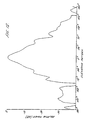
- Figure 12 illustrates the elevation beam pattern obtained using the antenna in Figure 11. In the pattern three shoulders corresponding to interferences A, B and C can clearly be seen.
- the thickness of the layers was 0.02 ⁇ and this provides a beam width of 28°.
- a layer thickness of 0.03 ⁇ has also been tried and provides a beam width of 24°.
- Figure 13a illustrates a seven layer arrangement wherein the layers are all arranged in parallel.
- Figure 13b illustrates a five layer arrangement wherein the outermost layers taper at a constant rate from the rear end to the front end of the antenna.
- Figure 13c illustrates a five layer arrangement wherein the outermost layers taper from the rear end to the front end of the antenna at an increasing rate.
- Figure 13d illustrates a five layer arrangement wherein the outermost layers taper from a rear end to a front end of the antenna at a deceasing rate.
- Figures 14a through d illustrate further embodiments of the present invention.
- Figure 14a illustrates a five layer arrangement wherein the spacings between all of these layers tapers from the rear end to a front end of the antenna.
- Figure 14b illustrates a five layer arrangement wherein all of the layers are arranged parallel to the axis but the thickness of the outermost layers tapers from a rear end to a front end of the antenna. This modifies the electric field distribution within and radiating from the dielectric structure.
- Figure 14c illustrates an inverse arrangement to Figure 14b wherein the structure comprises five parallel layers wherein the three inner layers have a thickness which tapers from the rear end to the front end of the antenna.
- Figure 14d illustrates a five layer antenna wherein the layers are arranged in parallel.
- the slotted waveguide 30 comprises a broad wall radiating waveguide. This is advantageous since this improves the polarisation purity compared with that provided by slots in the narrow wall of the waveguide.
- the layers have all been described as planar and thus the beam pattern is only shaped in the vertical plane by the configuration of the dielectric layers.
- the beam in the horizontal plane is formed by the amplitude distribution from the linear array of waveguide slots.
- the present invention is not restricted to the use of planar layers and layers can be used which simultaneously form the beam pattern in the vertical and horizontal planes.
- Figure 15 illustrates a longitudinal section through a six layer antenna which is coupled to a waveguide 40 by a transition portion 41.
- Figures 16a, 16b, 17a and 17b illustrate different possible cross-sections through X-X of Figure 15 depending on the beam pattern required in the vertical and horizontal planes. As can be seen in these drawings the six layers appearing in cross-section actually form three concentric hollow members.
- the beam pattern in a vertical axis is different from that in the horizontal axis, i.e. the elevation and azimuth beam patterns are different.
- Figure 17a illustrates an arrangement which will provide for a beam pattern which will vary continuously from the vertical axis to the horizontal axis whilst Figure 17b illustrates an arrangement which will provide for a beam pattern which has symmetry about the axis Y.
- Figures 18a, 18b, 19a and 19b illustrate cross-sections of further arrangements for forming a two-dimensional beam pattern.
- a plurality of parallel dielectric sheets 51 and 61 are provided to form a beam in the vertical direction as described hereinabove with reference to Figures 7 to 14.
- a plurality of perpendicular dielectric sheets 50 and 60 are provided which intersect the sheets 51 and 61, and which form a beam in the horizontal direction in a similar manner.
- the sheets 50, 51, 60 and 61 are shown to be equally spaced to form an equal beam shape in the two directions, the sheets 50 and 60 could be differently spaced to sheets 51 and 61 if differing beam patterns in the two directions is desired.
- the present invention provides many advantages. By utilising spaced layers which can either be arranged as planes or extend around an axis to form substantially concentric hollow members, a lightweight antenna of simple and less expensive construction is provided which provides the desired beam width but with reduced cross-sectional dimensions and thus an advantageous aerodynamic shape.
- the elimination of the flared feedhorn is an advantage since this provides a "cleaner" aerodynamic shape and attractive appearance.
- the length of the projection of the dielectric laminate structure is not excessive and thus in the planar configuration the area presented to up draught in strong wind conditions is reduced.
- the construction can thus ideally be made to have a length to height ratio of 4:1 which is aerodynamically and mechanically preferred. Also, strong attachment of the dielectric is not required since support is provided by the rigidity of the antenna body.
Landscapes
- Waveguide Aerials (AREA)
- Variable-Direction Aerials And Aerial Arrays (AREA)
- Aerials With Secondary Devices (AREA)
Claims (28)
- Antenne zum Senden oder/und Empfangen elektromagnetischer Strahlung entlang einer Achse, umfassend: zumindest vier aus dielektrischem Material gebildete Schichten (20a, 20b, 20c, 20d, 20e), die in Richtung orthogonal zu der Achse mit Abstand voneinander angeordnet sind, wobei die äußersten Schichten um zumindest die Hälfte der Wellenlänge (λ) der elektromagnetischen Strahlung mit Abstand von einander angeordnet sind, wobei sich die Schichten allgemein in Richtung der Achse von einem Hinterende zu einem Vorderende der Schichten erstrecken; einen Wellenleiter (21); und einen Übergangsabschnitt (22), der dazu ausgelegt ist, die Schichten direkt mit dem Wellenleiter elektromagnetisch zu koppeln; wobei ein Vorderende des Übergangsabschnitts mit dem Hinterende der Schichten verbunden ist und eine Dimension in Richtung orthogonal zu der Achse hat, die im Wesentlichen gleich dem Abstand zwischen den äußersten Schichten (20a, 20e) an dem Hinterende der Schichten ist; dadurch gekennzeichnet, dass die Trennung der einander nächsten Schichten (20a, 20b, 20c, 20d, 20e) weniger als die Hälfte der Wellenlänge (λ) der elektromagnetischen Strahlung beträgt und dass die durch Interferenz zwischen den äußersten Schichten (20a, 20e) erzeugten Schultern in dem Strahlenmuster wegen der erhöhten Anzahl von Schichten, die zur Interferenz beitragen können, reduziert sind.
- Antenne nach Anspruch 1, die fünf oder mehr der Schichten (20a, 20b, 20c, 20d, 20e) umfasst.
- Antenne zum Senden oder/und Empfangen elektromagnetischer Strahlung entlang einer Achse, umfassend: eine Mehrzahl aus dielektrischem Material gebildete Schichten (20a, 20b, 20c, 20d, 20e), die in Richtung orthogonal zu der Achse mit Abstand voneinander angeordnet sind, wobei die äußersten Schichten um zumindest die Hälfte der Wellenlänge (λ) der elektromagnetischen Strahlung mit Abstand von einander angeordnet sind, wobei sich die Schichten allgemein in Richtung der Achse von einem Hinterende zu einem Vorderende der Schichten erstrecken; einen Wellenleiter (21); und einen Übergangsabschnitt (22), der dazu ausgelegt ist, die Schichten direkt mit dem Wellenleiter elektromagnetisch zu koppeln; wobei ein Vorderende des Übergangsabschnitts mit dem Hinterende der Schichten verbunden ist und eine Dimension in Richtung orthogonal zu der Achse hat, die im Wesentlichen gleich dem Abstand zwischen den äußersten Schichten (20a, 20e) an dem Hinterende der Schichten ist; dadurch gekennzeichnet, dass nur drei der Schichten vorhanden sind und dass die durch Interferenz zwischen den äußersten Schichten (20a, 20e) erzeugten Schultern in dem Strahlenmuster wegen der erhöhten Anzahl von Schichten, die zur Interferenz beitragen können, reduziert sind.
- Antenne zum Senden oder/und Empfangen elektromagnetischer Strahlung entlang einer Achse, umfassend: eine Mehrzahl aus dielektrischem Material gebildete Schichten (20a, 20b, 20c, 20d, 20e), die in Richtung orthogonal zu der Achse mit Abstand voneinander angeordnet sind, wobei die äußersten Schichten um zumindest die Hälfte der Wellenlänge (λ) der elektromagnetischen Strahlung mit Abstand von einander angeordnet sind, wobei sich die Schichten allgemein in Richtung der Achse von einem Hinterende zu einem Vorderende der Schichten erstrecken; einen Wellenleiter (21); und einen Übergangsabschnitt (22), der mit dem Hinterende der Schichten verbunden und dazu ausgelegt ist, die Schichten mit dem Wellenleiter elektromagnetisch zu koppeln; dadurch gekennzeichnet, dass fünf oder mehr der Schichten vorgesehen sind und dass die durch Interferenz zwischen den äußersten Schichten (20a, 20e) erzeugten Schultern in dem Strahlenmuster wegen der erhöhten Anzahl von Schichten, die zur Interferenz beitragen können, reduziert sind.
- Antenne zum Senden oder/und Empfangen elektromagnetischer Strahlung entlang einer Achse, umfassend zumindest vier aus dielektrischem Material gebildeten Schichten (20a, 20b, 20c, 20d, 20e), wobei sich die Schichten allgemein in der Richtung der Achse von einem Hinterende zu einem Vorderende der Schichten erstrecken; einen Wellenleiter (21); und einen Übergangsabschnitt (22), der mit dem Hinterende der Schichten verbunden und dazu ausgelegt ist, die Schichten mit dem Wellenleiter elektromagnetisch zu koppeln,
dadurch gekennzeichnet, dass jede der Schichten (20a, 20b, 20c, 20d, 20e) einen mittleren Abstand von einer benachbarten Schicht in Richtung orthogonal zur Achse hat, der im Wesentlichen ein Viertel der Wellenlänge (λ) der elektromagnetischen Strahlung beträgt. - Antenne nach Anspruch 5, worin ein Vorderende des Übergangsabschnitts mit dem Hinterende der Schichten verbunden ist und eine Dimension in Richtung orthogonal zu der Achse hat, die im Wesentlichen gleich dem Abstand zwischen den äußersten Schichten an dem Hinterende der Schichten ist.
- Antenne nach einem der vorhergehenden Ansprüche, worin die Schichten (20a, 20b, 20c, 20d, 20e) im Wesentlichen symmetrisch um die Achse herum angeordnet sind.
- Antenne nach einem der vorhergehenden Ansprüche, worin sich die Schichten (20a, 20b, 20c, 20d, 20e) in Ebenen erstrecken und die Achse auf einer Mittelebene liegt, wobei die Schichten in Richtung orthogonal zu ihrer Mittelebene mit Abstand voneinander angeordnet sind.
- Antenne nach Anspruch 8, worin die Schichten (20a, 20b, 20c, 20d, 20e) um die Mittelebene herum spiegelsymmetrisch angeordnet sind.
- Antenne nach Anspruch 7 oder Anspruch 8, worin der Wellenleiter (21) ein Schlitz-Wellenleiter (21) ist und der Übergangsabschnitt (22) dazu ausgelegt ist, die Schichten (20a, 20b, 20c, 20d, 20e) direkt mit dem Schlitz-Wellenleiter zu koppeln.
- Antenne nach einem der Ansprüche 1 bis 6, worin sich die Schichten (20a, 20b, 20c, 20d, 20e) um die Achse herum erstrecken, zur Bildung im Wesentlichen konzentrischer hohler Elemente.
- Antenne nach einem der Ansprüche 1 bis 10, die zumindest drei weitere aus dielektrischem Material gebildete Schichten (20a, 20b, 20c, 20d, 20e) enthält, die in Richtung orthogonal zu der Achse und zu den Schichten (20a, 20b, 20c, 20d, 20e) mit Abstand voneinander angeordnet sind und die Schichten schneiden, wobei sich die weiteren Schichten allgemein in Richtung der Achse von dem Hinterende der Schichten zu dem Vorderende der Schichten erstrecken.
- Antenne nach einem der vorhergehenden Ansprüche, worin die Schichten (20a, 20b, 20c, 20d, 20e) mit im Wesentlichen gleichmäßigem Abstand voneinander angeordnet sind.
- Antenne nach einem der vorhergehenden Ansprüche, worin zwischen den Schichten (20a, 20b, 20c, 20d, 20e) Luft vorgesehen ist.
- Antenne nach einem der Ansprüche 1 bis 13, die ein zwischen den Schichten (20a, 20b, 20c, 20d, 20e) vorgesehenes zweites Material enthält, worin das zweite Material eine niedrige Dielektrizitätskonstante im Vergleich zu der Dielektrizitätskonstante des die Schichten bildenden Materials hat.
- Antenne nach Anspruch 15, worin das zweite Material aufgeschäumtes Polystyrol umfasst.
- Antenne nach Anspruch 15, worin das zweite Material aufgeschäumtes Polyurethan umfasst.
- Antenne nach einem der vorhergehenden Ansprüche, worin die Schichten (20a, 20b, 20c, 20d, 20e) im Wesentlichen parallel zu der Achse angeordnet sind.
- Antenne nach einem der Ansprüche 1 bis 17, worin sich der Abstand zwischen den Schichten (20a, 20b, 20c, 20d, 20e) vom Hinterende zum Vorderende verjüngt.
- Antenne nach einem der Ansprüche 1 bis 17, worin sich der Abstand zwischen den äußersten Schichten (20a, 20e) vom Hinterende zum Vorderende verjüngt.
- Antenne nach einem der vorhergehenden Ansprüche, worin sich die Dicke der äußersten Schichten (20a, 20e) vom Hinterende zum Vorderende verjüngt.
- Antenne nach einem der vorhergehenden Ansprüche, worin sich die Dicke der oder jeder Schicht (20b, 20c, 20d) zwischen den äußersten Schichten (20a, 20e) vom Hinterende zum Vorderende verjüngt.
- Antenne nach einem der vorhergehenden Ansprüche, worin die Schichten (20a, 20b, 20c, 20d, 20e) eine mittlere Dicke von zwischen 1 und 5 Hundertstel der Wellenlänge der elektromagnetischen Strahlung haben.
- Antenne nach Anspruch 23, worin die Schichten (20a, 20b, 20c, 20d, 20e) eine mittlere Dicke von zwischen 2 und 4 Hundertstel der Wellenlänge der elektromagnetischen Strahlung haben.
- Antenne nach einem der vorhergehenden Ansprüche, worin die Schichten (20a, 20b, 20c, 20d, 20e) aus Polyethylen gebildet sind.
- Antenne nach einem der vorhergehenden Ansprüche, worin die Schichten (20a, 20b, 20c, 20d, 20e) aus Polycarbon gebildet sind.
- Antenne nach einem der vorhergehenden Ansprüche, worin das Verhältnis der Länge der Antenne in Richtung der Achse zum mittleren Abstand zwischen den äußersten Schichten (20a, 20e) im Wesentlichen 4:1 beträgt.
- Antenne nach einem der Ansprüche 1 bis 3 oder einem der Ansprüche 7 bis 27, sofern von einem der Ansprüche 1 bis 3 abhängig, worin der mittlere Abstand zwischen den Schichten (20a, 20b, 20c, 20d, 20e) im Wesentlichen ein Viertel der Wellenlänge der elektromagnetischen Strahlung beträgt.
Applications Claiming Priority (3)
| Application Number | Priority Date | Filing Date | Title |
|---|---|---|---|
| GB9407845A GB9407845D0 (en) | 1994-04-20 | 1994-04-20 | An antenna |
| GB9407845 | 1994-04-20 | ||
| PCT/GB1995/000871 WO1995029518A1 (en) | 1994-04-20 | 1995-04-18 | An antenna |
Publications (2)
| Publication Number | Publication Date |
|---|---|
| EP0705488A1 EP0705488A1 (de) | 1996-04-10 |
| EP0705488B1 true EP0705488B1 (de) | 2003-01-08 |
Family
ID=10753840
Family Applications (1)
| Application Number | Title | Priority Date | Filing Date |
|---|---|---|---|
| EP95915275A Expired - Lifetime EP0705488B1 (de) | 1994-04-20 | 1995-04-18 | Antenne |
Country Status (10)
| Country | Link |
|---|---|
| US (1) | US5757330A (de) |
| EP (1) | EP0705488B1 (de) |
| JP (1) | JP3634372B2 (de) |
| KR (1) | KR100366070B1 (de) |
| AU (1) | AU2221695A (de) |
| CA (1) | CA2165569C (de) |
| DE (1) | DE69529322T2 (de) |
| DK (1) | DK0705488T3 (de) |
| GB (1) | GB9407845D0 (de) |
| WO (1) | WO1995029518A1 (de) |
Families Citing this family (8)
| Publication number | Priority date | Publication date | Assignee | Title |
|---|---|---|---|---|
| EP0947812A1 (de) | 1998-03-28 | 1999-10-06 | Endress + Hauser GmbH + Co. | Mit Mikrowellen arbeitendes Füllstandsmessgerät |
| JP2001320228A (ja) * | 2000-03-03 | 2001-11-16 | Anritsu Corp | 誘電体漏れ波アンテナ |
| GB0030932D0 (en) * | 2000-12-19 | 2001-01-31 | Radiant Networks Plc | Antenna apparatus, communications apparatus and method of transmission |
| GB0127772D0 (en) | 2001-11-20 | 2002-01-09 | Smiths Group Plc | Antennas |
| JP4733582B2 (ja) * | 2006-07-24 | 2011-07-27 | 古野電気株式会社 | アンテナ装置 |
| JP5219794B2 (ja) * | 2008-12-26 | 2013-06-26 | 古野電気株式会社 | 誘電体アンテナ |
| US8330651B2 (en) * | 2009-11-23 | 2012-12-11 | Honeywell International Inc. | Single-antenna FM/CW marine radar |
| JP5639015B2 (ja) * | 2011-07-06 | 2014-12-10 | 古野電気株式会社 | アンテナ装置、レーダ装置、及び誘電体部材の配置方法 |
Family Cites Families (15)
| Publication number | Priority date | Publication date | Assignee | Title |
|---|---|---|---|---|
| US2785397A (en) * | 1946-03-19 | 1957-03-12 | Rca Corp | Annular lens antenna |
| US2743440A (en) * | 1951-07-19 | 1956-04-24 | Henry J Riblet | Electromagnetic horn |
| US3366829A (en) * | 1965-01-19 | 1968-01-30 | Roger E. Clapp | Interactions between waves and electrons |
| GB1133343A (en) * | 1965-09-17 | 1968-11-13 | Nat Res Dev | Improvements in or relating to aerial systems |
| US3854141A (en) * | 1973-08-02 | 1974-12-10 | United Atlantic Corp | Zoom interferometer antenna |
| US4488157A (en) * | 1982-02-22 | 1984-12-11 | Tokyo Keiki Company Limited | Slot array antenna assembly |
| JPS60178707A (ja) * | 1984-02-25 | 1985-09-12 | Tokyo Keiki Co Ltd | スロツト・アレイ・アンテナ装置 |
| JPS60216605A (ja) * | 1984-03-10 | 1985-10-30 | Tokyo Keiki Co Ltd | スロツト・アレイ・アンテナ装置 |
| GB2157082B (en) * | 1984-02-16 | 1987-07-29 | Tokyo Keiki Kk | Slotted waveguide antenna assembly |
| GB2158650B (en) * | 1984-03-14 | 1987-12-23 | Tokyo Keiki Kk | Slotted waveguide antenna assembly |
| US4677404A (en) * | 1984-12-19 | 1987-06-30 | Martin Marietta Corporation | Compound dielectric multi-conductor transmission line |
| JPH0682975B2 (ja) * | 1986-01-24 | 1994-10-19 | 古野電気株式会社 | スロツトアレイアンテナ装置 |
| JPS63206006A (ja) * | 1987-02-21 | 1988-08-25 | Tokyo Keiki Co Ltd | スロツト・アレイ・アンテナ |
| JPH0760972B2 (ja) * | 1991-03-14 | 1995-06-28 | 日本無線株式会社 | 船舶レーダ装置用空中線 |
| US5461394A (en) * | 1992-02-24 | 1995-10-24 | Chaparral Communications Inc. | Dual band signal receiver |
-
1994
- 1994-04-20 GB GB9407845A patent/GB9407845D0/en active Pending
-
1995
- 1995-04-18 DE DE69529322T patent/DE69529322T2/de not_active Expired - Lifetime
- 1995-04-18 DK DK95915275T patent/DK0705488T3/da active
- 1995-04-18 EP EP95915275A patent/EP0705488B1/de not_active Expired - Lifetime
- 1995-04-18 AU AU22216/95A patent/AU2221695A/en not_active Abandoned
- 1995-04-18 US US08/557,144 patent/US5757330A/en not_active Expired - Lifetime
- 1995-04-18 WO PCT/GB1995/000871 patent/WO1995029518A1/en not_active Ceased
- 1995-04-18 CA CA002165569A patent/CA2165569C/en not_active Expired - Fee Related
- 1995-04-18 KR KR1019950705787A patent/KR100366070B1/ko not_active Expired - Lifetime
- 1995-04-18 JP JP52743995A patent/JP3634372B2/ja not_active Expired - Fee Related
Also Published As
| Publication number | Publication date |
|---|---|
| GB9407845D0 (en) | 1994-06-15 |
| DE69529322T2 (de) | 2003-09-04 |
| DK0705488T3 (da) | 2003-04-28 |
| JPH09504151A (ja) | 1997-04-22 |
| KR960703279A (ko) | 1996-06-19 |
| CA2165569C (en) | 2003-11-11 |
| US5757330A (en) | 1998-05-26 |
| WO1995029518A1 (en) | 1995-11-02 |
| CA2165569A1 (en) | 1995-11-02 |
| HK1012781A1 (en) | 1999-08-06 |
| EP0705488A1 (de) | 1996-04-10 |
| KR100366070B1 (ko) | 2003-03-06 |
| JP3634372B2 (ja) | 2005-03-30 |
| AU2221695A (en) | 1995-11-16 |
| DE69529322D1 (de) | 2003-02-13 |
Similar Documents
| Publication | Publication Date | Title |
|---|---|---|
| US5173714A (en) | Slot array antenna | |
| US5359338A (en) | Linear conformal antenna array for scanning near end-fire in one direction | |
| US7202832B2 (en) | Vehicle mounted satellite antenna system with ridged waveguide | |
| US6977621B2 (en) | Vehicle mounted satellite antenna system with inverted L-shaped waveguide | |
| US7466281B2 (en) | Integrated waveguide antenna and array | |
| CA2261625C (en) | Antenna system | |
| US5748153A (en) | Flared conductor-backed coplanar waveguide traveling wave antenna | |
| US7391381B2 (en) | Vehicle mounted satellite antenna system with in-motion tracking using beam forming | |
| US6429825B1 (en) | Cavity slot antenna | |
| JPH08321710A (ja) | 走査アンテナシステム | |
| US3995275A (en) | Reflector antenna having main and subreflector of diverse curvature | |
| EP0705488B1 (de) | Antenne | |
| AU620426B2 (en) | Slot array antenna | |
| JPH02260704A (ja) | 平面アンテナ | |
| US5883604A (en) | Horn antenna | |
| JP3472259B2 (ja) | 空洞が抑制された高次モードのマルチモード方形ホーン | |
| HK1012781B (en) | An antenna | |
| US4431997A (en) | Compound element for image element antennas | |
| US5187491A (en) | Low sidelobes antenna | |
| US4516129A (en) | Waveguide with dielectric coated flange antenna feed | |
| Harms et al. | Scan limitations of open-ended ridged waveguide phased array antennas for satellite communication | |
| JP3286512B2 (ja) | アンテナ装置および誘電体ユニット | |
| JP3860241B2 (ja) | 開口面アンテナ | |
| JPH06334431A (ja) | マイクロストリップアンテナ | |
| JPH0354423Y2 (de) |
Legal Events
| Date | Code | Title | Description |
|---|---|---|---|
| PUAI | Public reference made under article 153(3) epc to a published international application that has entered the european phase |
Free format text: ORIGINAL CODE: 0009012 |
|
| 17P | Request for examination filed |
Effective date: 19951109 |
|
| AK | Designated contracting states |
Kind code of ref document: A1 Designated state(s): DE DK GB IT NL |
|
| RAP1 | Party data changed (applicant data changed or rights of an application transferred) |
Owner name: SPERRY MARINE INC. |
|
| 17Q | First examination report despatched |
Effective date: 19981020 |
|
| RAP1 | Party data changed (applicant data changed or rights of an application transferred) |
Owner name: LITTON MARINE SYSTEMS INC. |
|
| GRAG | Despatch of communication of intention to grant |
Free format text: ORIGINAL CODE: EPIDOS AGRA |
|
| GRAG | Despatch of communication of intention to grant |
Free format text: ORIGINAL CODE: EPIDOS AGRA |
|
| GRAG | Despatch of communication of intention to grant |
Free format text: ORIGINAL CODE: EPIDOS AGRA |
|
| GRAH | Despatch of communication of intention to grant a patent |
Free format text: ORIGINAL CODE: EPIDOS IGRA |
|
| GRAH | Despatch of communication of intention to grant a patent |
Free format text: ORIGINAL CODE: EPIDOS IGRA |
|
| GRAA | (expected) grant |
Free format text: ORIGINAL CODE: 0009210 |
|
| AK | Designated contracting states |
Kind code of ref document: B1 Designated state(s): DE DK GB IT NL |
|
| REG | Reference to a national code |
Ref country code: GB Ref legal event code: FG4D |
|
| REF | Corresponds to: |
Ref document number: 69529322 Country of ref document: DE Date of ref document: 20030213 Kind code of ref document: P |
|
| REG | Reference to a national code |
Ref country code: DK Ref legal event code: T3 |
|
| PLBE | No opposition filed within time limit |
Free format text: ORIGINAL CODE: 0009261 |
|
| STAA | Information on the status of an ep patent application or granted ep patent |
Free format text: STATUS: NO OPPOSITION FILED WITHIN TIME LIMIT |
|
| 26N | No opposition filed |
Effective date: 20031009 |
|
| REG | Reference to a national code |
Ref country code: GB Ref legal event code: 732E Free format text: REGISTERED BETWEEN 20111103 AND 20111109 |
|
| REG | Reference to a national code |
Ref country code: DE Ref legal event code: R082 Ref document number: 69529322 Country of ref document: DE Representative=s name: PATENTANWAELTE WEICKMANN & WEICKMANN, DE Effective date: 20111201 Ref country code: DE Ref legal event code: R082 Ref document number: 69529322 Country of ref document: DE Representative=s name: WEICKMANN & WEICKMANN, DE Effective date: 20111201 Ref country code: DE Ref legal event code: R081 Ref document number: 69529322 Country of ref document: DE Owner name: NORTHROP GRUMMAN SYSTEMS CORPORATION (N.D.GES., US Free format text: FORMER OWNER: LITTON MARINE SYSTEMS INC., CHARLOTTESVILLE, VA., US Effective date: 20111201 Ref country code: DE Ref legal event code: R081 Ref document number: 69529322 Country of ref document: DE Owner name: NORTHROP GRUMMAN SYSTEMS CORPORATION (N.D.GES., US Free format text: FORMER OWNER: LITTON MARINE SYSTEMS INC., CHARLOTTESVILLE, US Effective date: 20111201 Ref country code: DE Ref legal event code: R081 Ref document number: 69529322 Country of ref document: DE Owner name: NORTHROP GRUMMAN SYSTEMS CORP. (N.D.GES.D. STA, US Free format text: FORMER OWNER: LITTON MARINE SYSTEMS INC., CHARLOTTESVILLE, US Effective date: 20111201 |
|
| REG | Reference to a national code |
Ref country code: DE Ref legal event code: R082 Ref document number: 69529322 Country of ref document: DE Representative=s name: PATENTANWAELTE WEICKMANN & WEICKMANN, DE Effective date: 20120726 Ref country code: DE Ref legal event code: R082 Ref document number: 69529322 Country of ref document: DE Representative=s name: WEICKMANN & WEICKMANN, DE Effective date: 20120726 Ref country code: DE Ref legal event code: R081 Ref document number: 69529322 Country of ref document: DE Owner name: NORTHROP GRUMMAN SYSTEMS CORPORATION (N.D.GES., US Free format text: FORMER OWNER: NORTHROP GRUMMAN CORP. (N.D.GES.D.STAATES DELAWARE), LOS ANGELES, CALIF., US Effective date: 20120726 Ref country code: DE Ref legal event code: R081 Ref document number: 69529322 Country of ref document: DE Owner name: NORTHROP GRUMMAN SYSTEMS CORPORATION (N.D.GES., US Free format text: FORMER OWNER: NORTHROP GRUMMAN CORP. (N.D.GES.D.STAATES DELAWARE), LOS ANGELES, US Effective date: 20120726 Ref country code: DE Ref legal event code: R081 Ref document number: 69529322 Country of ref document: DE Owner name: NORTHROP GRUMMAN SYSTEMS CORP. (N.D.GES.D. STA, US Free format text: FORMER OWNER: NORTHROP GRUMMAN CORP. (N.D.GES.D.STAATES DELAWARE), LOS ANGELES, US Effective date: 20120726 |
|
| REG | Reference to a national code |
Ref country code: DE Ref legal event code: R082 Ref document number: 69529322 Country of ref document: DE Representative=s name: WEICKMANN & WEICKMANN, DE |
|
| REG | Reference to a national code |
Ref country code: DE Ref legal event code: R082 Ref document number: 69529322 Country of ref document: DE Representative=s name: PATENTANWAELTE WEICKMANN & WEICKMANN, DE Effective date: 20121211 Ref country code: DE Ref legal event code: R082 Ref document number: 69529322 Country of ref document: DE Representative=s name: WEICKMANN & WEICKMANN, DE Effective date: 20121211 Ref country code: DE Ref legal event code: R081 Ref document number: 69529322 Country of ref document: DE Owner name: NORTHROP GRUMMAN SYSTEMS CORPORATION (N.D.GES., US Free format text: FORMER OWNER: NORTHROP GRUMMAN SYSTEMS CORP. (N.D.GES.D. STAATES DELAWARE), LOS ANGELES, CALIF., US Effective date: 20121211 Ref country code: DE Ref legal event code: R081 Ref document number: 69529322 Country of ref document: DE Owner name: NORTHROP GRUMMAN SYSTEMS CORPORATION (N.D.GES., US Free format text: FORMER OWNER: NORTHROP GRUMMAN SYSTEMS CORP. (N.D.GES.D. STAATES DELAWARE), LOS ANGELES, US Effective date: 20121211 |
|
| PGFP | Annual fee paid to national office [announced via postgrant information from national office to epo] |
Ref country code: DE Payment date: 20130419 Year of fee payment: 19 Ref country code: GB Payment date: 20130418 Year of fee payment: 19 Ref country code: DK Payment date: 20130418 Year of fee payment: 19 |
|
| PGFP | Annual fee paid to national office [announced via postgrant information from national office to epo] |
Ref country code: NL Payment date: 20130418 Year of fee payment: 19 Ref country code: IT Payment date: 20130424 Year of fee payment: 19 |
|
| REG | Reference to a national code |
Ref country code: DE Ref legal event code: R119 Ref document number: 69529322 Country of ref document: DE |
|
| REG | Reference to a national code |
Ref country code: DK Ref legal event code: EBP Effective date: 20140430 |
|
| REG | Reference to a national code |
Ref country code: NL Ref legal event code: V1 Effective date: 20141101 |
|
| GBPC | Gb: european patent ceased through non-payment of renewal fee |
Effective date: 20140418 |
|
| REG | Reference to a national code |
Ref country code: DE Ref legal event code: R119 Ref document number: 69529322 Country of ref document: DE Effective date: 20141101 |
|
| PG25 | Lapsed in a contracting state [announced via postgrant information from national office to epo] |
Ref country code: DE Free format text: LAPSE BECAUSE OF NON-PAYMENT OF DUE FEES Effective date: 20141101 Ref country code: GB Free format text: LAPSE BECAUSE OF NON-PAYMENT OF DUE FEES Effective date: 20140418 |
|
| PG25 | Lapsed in a contracting state [announced via postgrant information from national office to epo] |
Ref country code: NL Free format text: LAPSE BECAUSE OF NON-PAYMENT OF DUE FEES Effective date: 20141101 |
|
| PG25 | Lapsed in a contracting state [announced via postgrant information from national office to epo] |
Ref country code: IT Free format text: LAPSE BECAUSE OF NON-PAYMENT OF DUE FEES Effective date: 20140418 |
|
| PG25 | Lapsed in a contracting state [announced via postgrant information from national office to epo] |
Ref country code: DK Free format text: LAPSE BECAUSE OF NON-PAYMENT OF DUE FEES Effective date: 20140430 |