EP0705374B1 - Wärmeisolierende aussenwand für gebäude - Google Patents
Wärmeisolierende aussenwand für gebäude Download PDFInfo
- Publication number
- EP0705374B1 EP0705374B1 EP93916340A EP93916340A EP0705374B1 EP 0705374 B1 EP0705374 B1 EP 0705374B1 EP 93916340 A EP93916340 A EP 93916340A EP 93916340 A EP93916340 A EP 93916340A EP 0705374 B1 EP0705374 B1 EP 0705374B1
- Authority
- EP
- European Patent Office
- Prior art keywords
- layer
- air gap
- wall
- air
- insulating layer
- Prior art date
- Legal status (The legal status is an assumption and is not a legal conclusion. Google has not performed a legal analysis and makes no representation as to the accuracy of the status listed.)
- Revoked
Links
- 239000003570 air Substances 0.000 claims abstract description 60
- 239000000463 material Substances 0.000 claims abstract description 11
- 239000012080 ambient air Substances 0.000 claims abstract description 3
- 239000002245 particle Substances 0.000 claims abstract description 3
- 239000011490 mineral wool Substances 0.000 claims description 5
- 238000001914 filtration Methods 0.000 claims description 4
- 238000010438 heat treatment Methods 0.000 claims description 4
- 210000002268 wool Anatomy 0.000 claims description 4
- 230000003319 supportive effect Effects 0.000 claims description 3
- 239000011362 coarse particle Substances 0.000 claims description 2
- 239000002184 metal Substances 0.000 claims description 2
- 230000035699 permeability Effects 0.000 claims 1
- 239000000284 extract Substances 0.000 abstract 1
- 238000009413 insulation Methods 0.000 description 9
- 238000009423 ventilation Methods 0.000 description 4
- 239000011230 binding agent Substances 0.000 description 2
- 238000010276 construction Methods 0.000 description 2
- 241000238631 Hexapoda Species 0.000 description 1
- 206010020751 Hypersensitivity Diseases 0.000 description 1
- 230000007815 allergy Effects 0.000 description 1
- 230000005540 biological transmission Effects 0.000 description 1
- 239000011449 brick Substances 0.000 description 1
- 239000007921 spray Substances 0.000 description 1
- 239000002023 wood Substances 0.000 description 1
Images
Classifications
-
- F—MECHANICAL ENGINEERING; LIGHTING; HEATING; WEAPONS; BLASTING
- F24—HEATING; RANGES; VENTILATING
- F24F—AIR-CONDITIONING; AIR-HUMIDIFICATION; VENTILATION; USE OF AIR CURRENTS FOR SCREENING
- F24F5/00—Air-conditioning systems or apparatus not covered by F24F1/00 or F24F3/00, e.g. using solar heat or combined with household units such as an oven or water heater
- F24F5/0075—Systems using thermal walls, e.g. double window
-
- E—FIXED CONSTRUCTIONS
- E04—BUILDING
- E04B—GENERAL BUILDING CONSTRUCTIONS; WALLS, e.g. PARTITIONS; ROOFS; FLOORS; CEILINGS; INSULATION OR OTHER PROTECTION OF BUILDINGS
- E04B1/00—Constructions in general; Structures which are not restricted either to walls, e.g. partitions, or floors or ceilings or roofs
- E04B1/62—Insulation or other protection; Elements or use of specified material therefor
- E04B1/70—Drying or keeping dry, e.g. by air vents
- E04B1/7069—Drying or keeping dry, e.g. by air vents by ventilating
-
- E—FIXED CONSTRUCTIONS
- E04—BUILDING
- E04B—GENERAL BUILDING CONSTRUCTIONS; WALLS, e.g. PARTITIONS; ROOFS; FLOORS; CEILINGS; INSULATION OR OTHER PROTECTION OF BUILDINGS
- E04B1/00—Constructions in general; Structures which are not restricted either to walls, e.g. partitions, or floors or ceilings or roofs
- E04B1/62—Insulation or other protection; Elements or use of specified material therefor
- E04B1/74—Heat, sound or noise insulation, absorption, or reflection; Other building methods affording favourable thermal or acoustical conditions, e.g. accumulating of heat within walls
- E04B1/76—Heat, sound or noise insulation, absorption, or reflection; Other building methods affording favourable thermal or acoustical conditions, e.g. accumulating of heat within walls specifically with respect to heat only
- E04B1/7675—Insulating linings for the interior face of exterior walls
-
- F—MECHANICAL ENGINEERING; LIGHTING; HEATING; WEAPONS; BLASTING
- F24—HEATING; RANGES; VENTILATING
- F24D—DOMESTIC- OR SPACE-HEATING SYSTEMS, e.g. CENTRAL HEATING SYSTEMS; DOMESTIC HOT-WATER SUPPLY SYSTEMS; ELEMENTS OR COMPONENTS THEREFOR
- F24D3/00—Hot-water central heating systems
- F24D3/12—Tube and panel arrangements for ceiling, wall, or underfloor heating
- F24D3/14—Tube and panel arrangements for ceiling, wall, or underfloor heating incorporated in a ceiling, wall or floor
- F24D3/145—Convecting elements concealed in wall or floor
-
- F—MECHANICAL ENGINEERING; LIGHTING; HEATING; WEAPONS; BLASTING
- F24—HEATING; RANGES; VENTILATING
- F24D—DOMESTIC- OR SPACE-HEATING SYSTEMS, e.g. CENTRAL HEATING SYSTEMS; DOMESTIC HOT-WATER SUPPLY SYSTEMS; ELEMENTS OR COMPONENTS THEREFOR
- F24D3/00—Hot-water central heating systems
- F24D3/12—Tube and panel arrangements for ceiling, wall, or underfloor heating
- F24D3/14—Tube and panel arrangements for ceiling, wall, or underfloor heating incorporated in a ceiling, wall or floor
- F24D3/147—Tube and panel arrangements for ceiling, wall, or underfloor heating incorporated in a ceiling, wall or floor arranged in facades
-
- F—MECHANICAL ENGINEERING; LIGHTING; HEATING; WEAPONS; BLASTING
- F24—HEATING; RANGES; VENTILATING
- F24S—SOLAR HEAT COLLECTORS; SOLAR HEAT SYSTEMS
- F24S20/00—Solar heat collectors specially adapted for particular uses or environments
- F24S20/60—Solar heat collectors integrated in fixed constructions, e.g. in buildings
- F24S20/66—Solar heat collectors integrated in fixed constructions, e.g. in buildings in the form of facade constructions, e.g. wall constructions
-
- E—FIXED CONSTRUCTIONS
- E04—BUILDING
- E04B—GENERAL BUILDING CONSTRUCTIONS; WALLS, e.g. PARTITIONS; ROOFS; FLOORS; CEILINGS; INSULATION OR OTHER PROTECTION OF BUILDINGS
- E04B1/00—Constructions in general; Structures which are not restricted either to walls, e.g. partitions, or floors or ceilings or roofs
- E04B1/62—Insulation or other protection; Elements or use of specified material therefor
- E04B1/74—Heat, sound or noise insulation, absorption, or reflection; Other building methods affording favourable thermal or acoustical conditions, e.g. accumulating of heat within walls
- E04B1/76—Heat, sound or noise insulation, absorption, or reflection; Other building methods affording favourable thermal or acoustical conditions, e.g. accumulating of heat within walls specifically with respect to heat only
- E04B2001/7679—Means preventing cold bridging at the junction of an exterior wall with an interior wall or a floor
-
- Y—GENERAL TAGGING OF NEW TECHNOLOGICAL DEVELOPMENTS; GENERAL TAGGING OF CROSS-SECTIONAL TECHNOLOGIES SPANNING OVER SEVERAL SECTIONS OF THE IPC; TECHNICAL SUBJECTS COVERED BY FORMER USPC CROSS-REFERENCE ART COLLECTIONS [XRACs] AND DIGESTS
- Y02—TECHNOLOGIES OR APPLICATIONS FOR MITIGATION OR ADAPTATION AGAINST CLIMATE CHANGE
- Y02A—TECHNOLOGIES FOR ADAPTATION TO CLIMATE CHANGE
- Y02A30/00—Adapting or protecting infrastructure or their operation
-
- Y—GENERAL TAGGING OF NEW TECHNOLOGICAL DEVELOPMENTS; GENERAL TAGGING OF CROSS-SECTIONAL TECHNOLOGIES SPANNING OVER SEVERAL SECTIONS OF THE IPC; TECHNICAL SUBJECTS COVERED BY FORMER USPC CROSS-REFERENCE ART COLLECTIONS [XRACs] AND DIGESTS
- Y02—TECHNOLOGIES OR APPLICATIONS FOR MITIGATION OR ADAPTATION AGAINST CLIMATE CHANGE
- Y02B—CLIMATE CHANGE MITIGATION TECHNOLOGIES RELATED TO BUILDINGS, e.g. HOUSING, HOUSE APPLIANCES OR RELATED END-USER APPLICATIONS
- Y02B10/00—Integration of renewable energy sources in buildings
- Y02B10/20—Solar thermal
-
- Y—GENERAL TAGGING OF NEW TECHNOLOGICAL DEVELOPMENTS; GENERAL TAGGING OF CROSS-SECTIONAL TECHNOLOGIES SPANNING OVER SEVERAL SECTIONS OF THE IPC; TECHNICAL SUBJECTS COVERED BY FORMER USPC CROSS-REFERENCE ART COLLECTIONS [XRACs] AND DIGESTS
- Y02—TECHNOLOGIES OR APPLICATIONS FOR MITIGATION OR ADAPTATION AGAINST CLIMATE CHANGE
- Y02B—CLIMATE CHANGE MITIGATION TECHNOLOGIES RELATED TO BUILDINGS, e.g. HOUSING, HOUSE APPLIANCES OR RELATED END-USER APPLICATIONS
- Y02B30/00—Energy efficient heating, ventilation or air conditioning [HVAC]
- Y02B30/90—Passive houses; Double facade technology
-
- Y—GENERAL TAGGING OF NEW TECHNOLOGICAL DEVELOPMENTS; GENERAL TAGGING OF CROSS-SECTIONAL TECHNOLOGIES SPANNING OVER SEVERAL SECTIONS OF THE IPC; TECHNICAL SUBJECTS COVERED BY FORMER USPC CROSS-REFERENCE ART COLLECTIONS [XRACs] AND DIGESTS
- Y02—TECHNOLOGIES OR APPLICATIONS FOR MITIGATION OR ADAPTATION AGAINST CLIMATE CHANGE
- Y02E—REDUCTION OF GREENHOUSE GAS [GHG] EMISSIONS, RELATED TO ENERGY GENERATION, TRANSMISSION OR DISTRIBUTION
- Y02E10/00—Energy generation through renewable energy sources
- Y02E10/40—Solar thermal energy, e.g. solar towers
Definitions
- the invention relates to a heat-insulating external wall for a building, in accordance with the preamble of Claim 1.
- Walls of this general type are, for example, known from DE-A-3 530 884.
- the basic technical requirements placed on conventional external walls of buildings is that the walls shall function as a climate shell in the building, and that they possibly shall also have a load-bearing capacity.
- the heat-insulating capacity of external walls has constantly increased in significance in recent years.
- the heat-insulating capacity has been increased by increasing the thickness of the insulating layer in the wall.
- the object of the invention is to provide a heat-insulating external wall which is a further development of the aforedescribed concepts of dynamic insulation, and it is the intention that the inventive wall, in addition to improving insulation capacity, shall also be used for ventilating the building interior and for filtering and pre-heating the through-passing air, so that the ventilation air flowing into the building will be held attemperated and free from particles that may be harmful to people suffering from allergies.
- This object is achieved by constructing the wall in accordance with the features set forth in the characterizing clause of Claim 1.
- Suitable embodiments of the inventive wall are defined in the subordinate Claims.
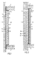
- Figure 1 is a cross-sectional view of an external wall 1 for a building, of which only parts of two floor structures 2 are shown together with said walls.
- the external wall 1 includes an outer lining or facing layer 3, which forms the outside of the wall and which is shown in Figure 1 to be a brick wall.
- the outer facing layer 3 may be built from other suitable materials, such as concrete, sheets of different kinds or wood panelling.
- the outer facing layer 3 is also provided with at least one inlet opening 4, which may be fitted with a grid or insect net (not shown).
- an outer air gap 5 which extends over the whole surface of the wall 1.
- an insulating layer 6 which forms the main insulation in the wall 1 and which is preferably comprised of mineral wool.
- an inner air gap 7 Located inwardly of the insulating layer 6 is an inner air gap 7, which is delimited outwardly by an inner facing or lining layer 8, which forms the inside of the wall 1 and delimits the wall against the building interior 9.
- a distributing layer 10 which in the case of the Figure 1 embodiment is disposed as the inner defining surface of the insulating layer 6.
- the inner facing layer 8 is a dense or impervious layer which is provided in the vicinity of its upper end with an outlet opening 11. Mounted in the opening 11 is a flow control device 12 which functions to control the flow of air through the outlet opening 11.
- the external wall illustrated in Figure 1 functions as follows: A subpressure is generated in the building interior 9 in a known manner.
- the devices used to this end form no part of the present invention and are therefore not shown in the drawings.
- ambient air is drawn in through the inlet opening 4 by suction and is distributed in the outer air gap 5.
- the air passes from the gap through an outer layer 13, through the insulating layer 6 and through the distribution layer 10 and into the inner air gap 7, from where the air through the outlet opening sprays into the building interior 9.
- the flow is controlled by the flow control device 12, which also prevents the air from flowing in the wrong direction.
- the distribution layer 10, which in the case of the Figure 1 embodiment is disposed on the inside of the insulating layer 6, is comprised of a material which is generally impervious to air, and is provided with a large number of small perforations (similar to needle holes), which are distributed over the whole surface of the distributing layer 10. These perforations are so formed that the airflow passing through the insulating layer 6 is distributed generally uniformly over the whole surface of the insulating layer 6.
- the inwardly directed flow through the insulating layer 6, said flow having a very low rate of flow, will absorb the heat which is transmitted through the wall 1 from the building interior 9.
- the inner air gap 7 will thus contain preheated air, which is then delivered to the building interior 9 through the narrow outlet opening 11.
- the heat-insulating capacity of the wall 1 is thus better than if the insulating layer 6 were to be used without a flow of air therethrough.
- the insulating layer 6 When the insulating layer 6 is comprised of material that has good filtering properties, such as mineral wool for instance, the insulating layer 6 will also function as a filter for the passing air. This filter will have a very large surface area and thickness and the air moves very slowly through the filter, thereby imparting very good filtering ability to the filter. The air exiting through the outlet opening 11 will therefore be very clean.
- material that has good filtering properties such as mineral wool for instance
- the inventive external wall 1 will fulfil the conventional function of forming part of the shell of the building, and also the additional function of providing a highly effective filter for ventilation air passing to the interior of the building, wherewith the wall will also have an improved heat-insulating capacity because the ventilation air that passes through the wall will take up at least some of the heat which would otherwise be lost to the surroundings, whereby the inflowing air is also attemperated and delivered to the room in a soundless and draught-free fashion.
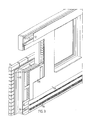
- Figure 2 illustrates an external wall 1 which is of the same principle construction as the external wall 1 illustrated in Figure 1.
- the external wall 1 of the Figure 2 embodiment is comprised of an external wall of an existing building with internal additional or supplementary insulation, in accordance with the invention.
- Those parts which find correspondence in Figure 1 have been identified in Figure 2 with the same reference signs, and the function of the wall shown in Figure 2 is the same as that of the wall shown in Figure 1.
- the main difference is that the outer facing layer is comprised of an outer layer 3a, an insulating layer 3b and an inner layer 3c which forms the inner side of the existing wall, which has been supplemented in accordance with the invention.
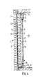
- Figures 3 and 4 illustrate an inventive external wall 1, wherein those parts that find correspondence in Figures 1 and 2 have been identified with the same reference signs.
- the distribution layer 10 is disposed on the outside of the insulating layer 6, instead of on the inside thereof.
- the outer layer 13 is located outwardly of the distribution layer 10 and functions as a first filter for extracting coarse particles from the air, so as to prevent clogging of the fine perforations in the distribution layer 10.
- the external wall 1 of the embodiment shown in Figures 3 and 4 is also provided with a third air gap 14 arranged between the inner air gap 7 and the inner facing layer 8.
- a third air gap 14 Located between the inner air gap 7 and the third air gap 14 is a thin intermediate layer 15 which is comprised of a material that has good thermal conductivity, for instance metal.
- the third air gap 14 is completely separate from the inner air gap 7 and the bottom of the gap 14 communicates with the building interior 9 through an inlet opening 16.
- the third air gap 14 is also open at the top of the gap, so as to form an outlet opening 17 to the building interior 9.
- At least one heating device 18 which functions to heat air that flows in through the inlet opening 16 and then rises up through the third air gap 14 and flows back into the building interior 9 through the outlet opening 17. In this way, there is produced a warm air flow through the third air gap 14, meaning that the inner facing layer 8 will be kept at a suitable temperature, therewith further reducing the risk of draughts or other discomfort in cold weather.
- the intermediate layer 15, which has good thermal conductivity, also contributes to further heating the ventilation air in the inner air gap 7, prior to said air exiting through the outlet opening 11.
- the insulating layer 6 can be made of so-called loose wool, i.e. mineral wool which is comprised of loose fibres in the absence of any binder. This alleviates the problem of possible departure of binder residues from the insulating layer 6.
- loose wool i.e. mineral wool which is comprised of loose fibres in the absence of any binder.
Landscapes
- Engineering & Computer Science (AREA)
- Physics & Mathematics (AREA)
- Architecture (AREA)
- Chemical & Material Sciences (AREA)
- Combustion & Propulsion (AREA)
- Mechanical Engineering (AREA)
- General Engineering & Computer Science (AREA)
- Life Sciences & Earth Sciences (AREA)
- Sustainable Development (AREA)
- Thermal Sciences (AREA)
- Civil Engineering (AREA)
- Electromagnetism (AREA)
- Structural Engineering (AREA)
- Sustainable Energy (AREA)
- Acoustics & Sound (AREA)
- Building Environments (AREA)
Claims (9)
- Wärmeisolierende Außenwand (1) für ein Gebäude, wobei die Wand eine außenliegende Verkleidungs- oder Deckschicht (3) enthält sowie einen äußeren Luftspalt (5), der innerhalb der äußeren Deckschicht (3) angeordnet ist, eine Isolierungsschicht (6), die innerhalb des äußeren Luftspaltes (5) angeordnet ist, einen inneren Luftspalt (7), der innerhalb der Isolierungsschicht (6) angeordnet ist, und eine innere Deckschicht (8), die innerhalb des inneren Luftspaltes (7) angeordnet ist, wobei der äußere Luftspalt (5) mit der Umgebungsluft durch wenigstens eine Einlaßöffnung (4) in der äußeren Deckschicht (3) in Verbindung steht und der innere Luftspalt (7) mit dem Inneren (9) des Gebäudes durch wenigstens eine Auslaßöffnung (11) in der inneren Deckschicht (8) in Verbindung steht, und wobei die Isolierungsschicht (6) aus einem Material besteht, das wenigstens in einer Richtung weg von dem äußeren Luftspalt zum inneren Luftspalt (7) hin luftdurchlässig ist,
dadurch gekennzeichnet, daß die Isolierungsschicht (6) aus einem Material besteht, das als ein Filter wirkt, der Partikel aus der vorbeiströmenden Luft herausnimmt, daß auf der Außenseite und/oder Innenseite der isolierenden Schicht (6) eine Verteilschicht (10) angeordnet ist, wobei die Verteilschicht (10) aus einem allgemein luftundurchlässigen Material besteht und mit einer großen Anzahl von gleichmäßig verteilten Löchern versehen ist oder ein Material mit gut ausgeglichener Porosität enthält, und daß eine Durchflußsteuervorrichtung (12) in der Auslaßöffnung (11) oder in deren Nähe angeordnet ist, um unabhängig von der Druckdifferenz zwischen der Außenseite der Wand (1) und ihrer Innenseite einen allgemein konstanten Luftstrom durch die Wand (1) aufrecht zu erhalten. - Wand nach Anspruch 1, dadurch gekennzeichnet, daß die Isolierungsschicht (6) aus Mineralwolleplatten besteht.
- Wand nach Anspruch 1, dadurch gekennzeichnet, daß die Isolierungsschicht (6) aus Mineralwolle in der Form von loser Wolle besteht, wobei eine tragende Schicht als ein Träger für die lose Wolle auf jeder Seite der Isolierungsschicht (6) vorgesehen ist.
- Wand nach einem der Ansprüche 1 bis 3, dadurch gekennzeichnet, daß die Durchflußsteuervorrichtung (12) ein druckgesteuertes Ventil ist, welches die Durchflußfläche automatisch in Abhängigkeit von der Druckdifferenz zwischen der Außenseite der Wand (1) und ihrer Innenseite einstellt.
- Wand nach einem der Ansprüche 1 bis 4, dadurch gekennzeichnet, daß die Verteilschicht (10) aus einer Platte besteht, die von Löchern durchbrochen ist, die eine geeignet ausgeglichene Luftdurchlässigkeit bereitstellen.
- Wand nach einem der Ansprüche 1 bis 5, dadurch gekennzeichnet, daß außerhalb der Verteilschicht (10) eine Filterschicht (13) angeordnet ist, um Grobpartikel aus der vorbeiströmenden Luft herauszunehmen.
- Wand nach einem der Ansprüche 1 bis 6, dadurch gekennzeichnet, daß zwischen dem inneren Luftspalt (7) und der inneren Deckschicht (8) eine dünne Zwischenschicht (15) und ein dritter Luftspalt (14) vorgesehen sind, wobei sowohl die Zwischenschicht als auch der dritte Luftspalt mit dem Inneren (9) des Gebäudes am oberen Abschnitt der Schicht und des Spaltes in Verbindung stehen.
- Wand nach Anspruch 7, dadurch gekennzeichnet, daß die Zwischenschicht (15) aus einem Material mit guter Wärmeleitfähigkeit besteht, beispielsweise Metall.
- Wand nach Anspruch 7 oder Anspruch 8, dadurch gekennzeichnet, daß in dem dritten Luftspalt eine Heizvorrichtung (18) angebracht ist.
Priority Applications (1)
| Application Number | Priority Date | Filing Date | Title |
|---|---|---|---|
| AT93916340T ATE158369T1 (de) | 1993-06-24 | 1993-06-24 | Wärmeisolierende aussenwand für gebäude |
Applications Claiming Priority (1)
| Application Number | Priority Date | Filing Date | Title |
|---|---|---|---|
| PCT/SE1993/000569 WO1995000722A1 (en) | 1993-06-24 | 1993-06-24 | Heat insulating external wall for buildings |
Publications (2)
| Publication Number | Publication Date |
|---|---|
| EP0705374A1 EP0705374A1 (de) | 1996-04-10 |
| EP0705374B1 true EP0705374B1 (de) | 1997-09-17 |
Family
ID=20388969
Family Applications (1)
| Application Number | Title | Priority Date | Filing Date |
|---|---|---|---|
| EP93916340A Revoked EP0705374B1 (de) | 1993-06-24 | 1993-06-24 | Wärmeisolierende aussenwand für gebäude |
Country Status (5)
| Country | Link |
|---|---|
| EP (1) | EP0705374B1 (de) |
| DE (1) | DE69314063T2 (de) |
| DK (1) | DK0705374T3 (de) |
| RU (1) | RU2109886C1 (de) |
| WO (1) | WO1995000722A1 (de) |
Families Citing this family (12)
| Publication number | Priority date | Publication date | Assignee | Title |
|---|---|---|---|---|
| US5875607A (en) * | 1996-08-28 | 1999-03-02 | The United States Of America As Represented By The United States Department Of Energy | Low-cost exterior insulation process and structure |
| RU2145992C1 (ru) * | 1999-03-17 | 2000-02-27 | Селиванов Вадим Николаевич | Конструкция ограждения с теплоизоляцией с активным удалением влаги |
| RU2144114C1 (ru) * | 1999-03-17 | 2000-01-10 | Селиванов Николай Павлович | Конструкция ограждения с теплоизоляцией с активным удалением влаги |
| TWI227702B (en) * | 2002-07-03 | 2005-02-11 | Asahi Kasei Corp | Calcium silicate hardened article |
| ATA16952002A (de) * | 2002-11-11 | 2004-06-15 | Griffner Ari | Gebäude |
| RU2296278C2 (ru) * | 2005-04-05 | 2007-03-27 | Сергей Борисович Бабакин | Холодильник для пищевых продуктов |
| EP2423398A1 (de) * | 2010-08-23 | 2012-02-29 | insu-fast GmbH | Vorrichtung zur Innenisolation einer Bauteilwand |
| NL1042468B1 (nl) * | 2017-07-19 | 2019-02-12 | Innovy | Klimaatregelsysteem met een doorstroombaar isolatiesamenstel |
| CN110553963A (zh) * | 2018-05-31 | 2019-12-10 | 北新集团建材股份有限公司 | 滤材应用检测系统 |
| JP7174995B2 (ja) * | 2018-10-19 | 2022-11-18 | 株式会社テスク | 通気層を有する密着型外断熱に用いられる火災対応型外壁構造、及び該火災対応型外壁構造に用いられる笠木 |
| NL2022003B1 (nl) * | 2018-11-15 | 2020-05-20 | Innovy | Isolatiesysteem met thermisch isolerende afscheiding |
| WO2025244521A1 (ru) * | 2024-05-21 | 2025-11-27 | Нао "Евразийский Национальный Университет Им. Л.Н. Гумилева" | Наружная стена здания |
Family Cites Families (4)
| Publication number | Priority date | Publication date | Assignee | Title |
|---|---|---|---|---|
| SE300297B (de) * | 1965-05-31 | 1968-04-22 | T Thoren | |
| DE2009002A1 (de) * | 1970-02-26 | 1971-11-11 | Hoch, Wilhelm, 8311 Marklkofen | Leichtbau-Verbundtafel mit Diffusionsdurchlass |
| SE403640B (sv) * | 1976-06-24 | 1978-08-28 | Thoren Torgny | Byggelement |
| DE3530884A1 (de) * | 1984-10-19 | 1986-04-30 | Kaufmann, Ralph A.H., 5000 Köln | Klimawand |
-
1993
- 1993-06-24 EP EP93916340A patent/EP0705374B1/de not_active Revoked
- 1993-06-24 DE DE69314063T patent/DE69314063T2/de not_active Expired - Fee Related
- 1993-06-24 WO PCT/SE1993/000569 patent/WO1995000722A1/en not_active Ceased
- 1993-06-24 RU RU96107409A patent/RU2109886C1/ru active
- 1993-06-24 DK DK93916340.8T patent/DK0705374T3/da active
Also Published As
| Publication number | Publication date |
|---|---|
| DE69314063D1 (de) | 1997-10-23 |
| RU2109886C1 (ru) | 1998-04-27 |
| EP0705374A1 (de) | 1996-04-10 |
| DE69314063T2 (de) | 1998-01-08 |
| WO1995000722A1 (en) | 1995-01-05 |
| DK0705374T3 (da) | 1998-04-14 |
Similar Documents
| Publication | Publication Date | Title |
|---|---|---|
| EP0705374B1 (de) | Wärmeisolierende aussenwand für gebäude | |
| US5799454A (en) | Heat insulating outer wall for a building | |
| RU96107409A (ru) | Теплоизолирующая внешняя стена здания | |
| DK162402B (da) | Fremgangsmaade til ventilering af et gulv | |
| JPH0519444Y2 (de) | ||
| AT413291B (de) | Dämmsystem für gebäudedecken | |
| SU1746896A3 (ru) | Паровентил ционна система кровли | |
| JP4722650B2 (ja) | 建築物 | |
| CA2403722C (en) | Method and apparatus for ventilation of foundations | |
| JP2564365B2 (ja) | 家 屋 | |
| JPH062375A (ja) | 家 屋 | |
| JP2663153B2 (ja) | 家 屋 | |
| JP2703776B2 (ja) | 家 屋 | |
| SU953128A1 (ru) | Стена вентилируемого здани | |
| RU2145992C1 (ru) | Конструкция ограждения с теплоизоляцией с активным удалением влаги | |
| EP0147827B1 (de) | Verfahren und Bauelemente zur Klimatisierung von Arbeits-, Wohn- und Aufenthaltsräumen | |
| JP4829582B2 (ja) | 外壁 | |
| WO1998058138A1 (en) | An arrangement for equalising the flow of ventilation air | |
| JPS6339307Y2 (de) | ||
| JPH03199544A (ja) | 断熱壁 | |
| JP3084312B2 (ja) | 家 屋 | |
| JPH01189439A (ja) | 家屋 | |
| JPH02272234A (ja) | 家屋 | |
| JPH01179834A (ja) | 家屋 | |
| JPH0356602Y2 (de) |
Legal Events
| Date | Code | Title | Description |
|---|---|---|---|
| PUAI | Public reference made under article 153(3) epc to a published international application that has entered the european phase |
Free format text: ORIGINAL CODE: 0009012 |
|
| 17P | Request for examination filed |
Effective date: 19960103 |
|
| AK | Designated contracting states |
Kind code of ref document: A1 Designated state(s): AT BE CH DE DK FR GB LI NL SE |
|
| GRAG | Despatch of communication of intention to grant |
Free format text: ORIGINAL CODE: EPIDOS AGRA |
|
| 17Q | First examination report despatched |
Effective date: 19970124 |
|
| GRAH | Despatch of communication of intention to grant a patent |
Free format text: ORIGINAL CODE: EPIDOS IGRA |
|
| GRAH | Despatch of communication of intention to grant a patent |
Free format text: ORIGINAL CODE: EPIDOS IGRA |
|
| GRAA | (expected) grant |
Free format text: ORIGINAL CODE: 0009210 |
|
| AK | Designated contracting states |
Kind code of ref document: B1 Designated state(s): AT BE CH DE DK FR GB LI NL SE |
|
| PG25 | Lapsed in a contracting state [announced via postgrant information from national office to epo] |
Ref country code: LI Free format text: LAPSE BECAUSE OF NON-PAYMENT OF DUE FEES Effective date: 19970917 Ref country code: CH Free format text: LAPSE BECAUSE OF NON-PAYMENT OF DUE FEES Effective date: 19970917 |
|
| REF | Corresponds to: |
Ref document number: 158369 Country of ref document: AT Date of ref document: 19971015 Kind code of ref document: T |
|
| REG | Reference to a national code |
Ref country code: CH Ref legal event code: NV Representative=s name: BOVARD AG PATENTANWAELTE Ref country code: CH Ref legal event code: EP |
|
| REF | Corresponds to: |
Ref document number: 69314063 Country of ref document: DE Date of ref document: 19971023 |
|
| ET | Fr: translation filed | ||
| PGFP | Annual fee paid to national office [announced via postgrant information from national office to epo] |
Ref country code: FR Payment date: 19980410 Year of fee payment: 6 |
|
| REG | Reference to a national code |
Ref country code: DK Ref legal event code: T3 |
|
| PGFP | Annual fee paid to national office [announced via postgrant information from national office to epo] |
Ref country code: BE Payment date: 19980428 Year of fee payment: 6 |
|
| PGFP | Annual fee paid to national office [announced via postgrant information from national office to epo] |
Ref country code: AT Payment date: 19980610 Year of fee payment: 6 |
|
| PGFP | Annual fee paid to national office [announced via postgrant information from national office to epo] |
Ref country code: GB Payment date: 19980615 Year of fee payment: 6 |
|
| PGFP | Annual fee paid to national office [announced via postgrant information from national office to epo] |
Ref country code: CH Payment date: 19980616 Year of fee payment: 6 |
|
| PLAV | Examination of admissibility of opposition |
Free format text: ORIGINAL CODE: EPIDOS OPEX |
|
| PLBQ | Unpublished change to opponent data |
Free format text: ORIGINAL CODE: EPIDOS OPPO |
|
| PLBI | Opposition filed |
Free format text: ORIGINAL CODE: 0009260 |
|
| PGFP | Annual fee paid to national office [announced via postgrant information from national office to epo] |
Ref country code: NL Payment date: 19980630 Year of fee payment: 6 |
|
| PLBF | Reply of patent proprietor to notice(s) of opposition |
Free format text: ORIGINAL CODE: EPIDOS OBSO |
|
| 26 | Opposition filed |
Opponent name: ROCKWOOL INTERNATIONAL A/S Effective date: 19980616 |
|
| NLR1 | Nl: opposition has been filed with the epo |
Opponent name: ROCKWOOL INTERNATIONAL A/S |
|
| PG25 | Lapsed in a contracting state [announced via postgrant information from national office to epo] |
Ref country code: GB Free format text: LAPSE BECAUSE OF NON-PAYMENT OF DUE FEES Effective date: 19990624 Ref country code: AT Free format text: LAPSE BECAUSE OF NON-PAYMENT OF DUE FEES Effective date: 19990624 |
|
| PG25 | Lapsed in a contracting state [announced via postgrant information from national office to epo] |
Ref country code: BE Free format text: LAPSE BECAUSE OF NON-PAYMENT OF DUE FEES Effective date: 19990630 |
|
| PGFP | Annual fee paid to national office [announced via postgrant information from national office to epo] |
Ref country code: DK Payment date: 19990630 Year of fee payment: 7 |
|
| PGFP | Annual fee paid to national office [announced via postgrant information from national office to epo] |
Ref country code: DE Payment date: 19990830 Year of fee payment: 7 |
|
| BERE | Be: lapsed |
Owner name: SKANSKA TEKNIK A.B. Effective date: 19990630 |
|
| PG25 | Lapsed in a contracting state [announced via postgrant information from national office to epo] |
Ref country code: NL Free format text: LAPSE BECAUSE OF NON-PAYMENT OF DUE FEES Effective date: 20000101 |
|
| RDAH | Patent revoked |
Free format text: ORIGINAL CODE: EPIDOS REVO |
|
| REG | Reference to a national code |
Ref country code: CH Ref legal event code: PL |
|
| GBPC | Gb: european patent ceased through non-payment of renewal fee |
Effective date: 19990624 |
|
| NLV4 | Nl: lapsed or anulled due to non-payment of the annual fee |
Effective date: 20000101 |
|
| RDAG | Patent revoked |
Free format text: ORIGINAL CODE: 0009271 |
|
| STAA | Information on the status of an ep patent application or granted ep patent |
Free format text: STATUS: PATENT REVOKED |
|
| PGFP | Annual fee paid to national office [announced via postgrant information from national office to epo] |
Ref country code: SE Payment date: 20000605 Year of fee payment: 8 |
|
| 27W | Patent revoked |
Effective date: 20000214 |
|
| REG | Reference to a national code |
Ref country code: FR Ref legal event code: ST |