EP0705186B2 - Einrichtung zur steuerung einer scheibenwischanlage - Google Patents
Einrichtung zur steuerung einer scheibenwischanlage Download PDFInfo
- Publication number
- EP0705186B2 EP0705186B2 EP94918290A EP94918290A EP0705186B2 EP 0705186 B2 EP0705186 B2 EP 0705186B2 EP 94918290 A EP94918290 A EP 94918290A EP 94918290 A EP94918290 A EP 94918290A EP 0705186 B2 EP0705186 B2 EP 0705186B2
- Authority
- EP
- European Patent Office
- Prior art keywords
- signals
- value
- signal
- sensor device
- wiper
- Prior art date
- Legal status (The legal status is an assumption and is not a legal conclusion. Google has not performed a legal analysis and makes no representation as to the accuracy of the status listed.)
- Expired - Lifetime
Links
- 238000009434 installation Methods 0.000 title 1
- 230000005855 radiation Effects 0.000 claims description 26
- 238000001514 detection method Methods 0.000 claims description 22
- 230000004044 response Effects 0.000 claims description 22
- 230000006399 behavior Effects 0.000 claims description 21
- 238000009736 wetting Methods 0.000 claims description 20
- 230000015654 memory Effects 0.000 claims description 19
- 230000035945 sensitivity Effects 0.000 claims description 17
- 230000001105 regulatory effect Effects 0.000 claims description 14
- 238000011156 evaluation Methods 0.000 claims description 7
- 230000001276 controlling effect Effects 0.000 claims description 6
- 238000010408 sweeping Methods 0.000 claims description 6
- 230000001960 triggered effect Effects 0.000 claims description 6
- 238000005259 measurement Methods 0.000 claims description 5
- 230000005693 optoelectronics Effects 0.000 claims description 4
- 230000003321 amplification Effects 0.000 claims description 2
- 238000003199 nucleic acid amplification method Methods 0.000 claims description 2
- 238000001914 filtration Methods 0.000 claims 1
- 238000000034 method Methods 0.000 description 21
- 230000008569 process Effects 0.000 description 21
- 238000010586 diagram Methods 0.000 description 6
- XLYOFNOQVPJJNP-UHFFFAOYSA-N water Substances O XLYOFNOQVPJJNP-UHFFFAOYSA-N 0.000 description 4
- 230000004888 barrier function Effects 0.000 description 3
- 230000001419 dependent effect Effects 0.000 description 3
- 230000000694 effects Effects 0.000 description 3
- 241000238631 Hexapoda Species 0.000 description 2
- 206010047571 Visual impairment Diseases 0.000 description 2
- 238000010422 painting Methods 0.000 description 2
- 230000009467 reduction Effects 0.000 description 2
- 230000001360 synchronised effect Effects 0.000 description 2
- 208000029257 vision disease Diseases 0.000 description 2
- 230000004393 visual impairment Effects 0.000 description 2
- 230000032683 aging Effects 0.000 description 1
- 230000008859 change Effects 0.000 description 1
- 238000006243 chemical reaction Methods 0.000 description 1
- 238000004140 cleaning Methods 0.000 description 1
- 239000011248 coating agent Substances 0.000 description 1
- 238000000576 coating method Methods 0.000 description 1
- 230000008878 coupling Effects 0.000 description 1
- 238000010168 coupling process Methods 0.000 description 1
- 238000005859 coupling reaction Methods 0.000 description 1
- 230000003247 decreasing effect Effects 0.000 description 1
- 238000001035 drying Methods 0.000 description 1
- 230000006870 function Effects 0.000 description 1
- 230000003993 interaction Effects 0.000 description 1
- 230000010355 oscillation Effects 0.000 description 1
- 230000002028 premature Effects 0.000 description 1
- 238000011084 recovery Methods 0.000 description 1
- 230000035939 shock Effects 0.000 description 1
- 230000008054 signal transmission Effects 0.000 description 1
- 230000002123 temporal effect Effects 0.000 description 1
- 230000036962 time dependent Effects 0.000 description 1
Images


Classifications
-
- G—PHYSICS
- G01—MEASURING; TESTING
- G01V—GEOPHYSICS; GRAVITATIONAL MEASUREMENTS; DETECTING MASSES OR OBJECTS; TAGS
- G01V8/00—Prospecting or detecting by optical means
- G01V8/10—Detecting, e.g. by using light barriers
- G01V8/20—Detecting, e.g. by using light barriers using multiple transmitters or receivers
-
- B—PERFORMING OPERATIONS; TRANSPORTING
- B60—VEHICLES IN GENERAL
- B60S—SERVICING, CLEANING, REPAIRING, SUPPORTING, LIFTING, OR MANOEUVRING OF VEHICLES, NOT OTHERWISE PROVIDED FOR
- B60S1/00—Cleaning of vehicles
- B60S1/02—Cleaning windscreens, windows or optical devices
- B60S1/04—Wipers or the like, e.g. scrapers
- B60S1/06—Wipers or the like, e.g. scrapers characterised by the drive
- B60S1/08—Wipers or the like, e.g. scrapers characterised by the drive electrically driven
- B60S1/0818—Wipers or the like, e.g. scrapers characterised by the drive electrically driven including control systems responsive to external conditions, e.g. by detection of moisture, dirt or the like
-
- G—PHYSICS
- G01—MEASURING; TESTING
- G01N—INVESTIGATING OR ANALYSING MATERIALS BY DETERMINING THEIR CHEMICAL OR PHYSICAL PROPERTIES
- G01N21/00—Investigating or analysing materials by the use of optical means, i.e. using sub-millimetre waves, infrared, visible or ultraviolet light
- G01N21/17—Systems in which incident light is modified in accordance with the properties of the material investigated
- G01N21/41—Refractivity; Phase-affecting properties, e.g. optical path length
- G01N21/43—Refractivity; Phase-affecting properties, e.g. optical path length by measuring critical angle
-
- G—PHYSICS
- G01—MEASURING; TESTING
- G01N—INVESTIGATING OR ANALYSING MATERIALS BY DETERMINING THEIR CHEMICAL OR PHYSICAL PROPERTIES
- G01N21/00—Investigating or analysing materials by the use of optical means, i.e. using sub-millimetre waves, infrared, visible or ultraviolet light
- G01N21/17—Systems in which incident light is modified in accordance with the properties of the material investigated
- G01N21/55—Specular reflectivity
-
- G—PHYSICS
- G01—MEASURING; TESTING
- G01N—INVESTIGATING OR ANALYSING MATERIALS BY DETERMINING THEIR CHEMICAL OR PHYSICAL PROPERTIES
- G01N21/00—Investigating or analysing materials by the use of optical means, i.e. using sub-millimetre waves, infrared, visible or ultraviolet light
- G01N21/84—Systems specially adapted for particular applications
- G01N21/8422—Investigating thin films, e.g. matrix isolation method
-
- G—PHYSICS
- G01—MEASURING; TESTING
- G01N—INVESTIGATING OR ANALYSING MATERIALS BY DETERMINING THEIR CHEMICAL OR PHYSICAL PROPERTIES
- G01N21/00—Investigating or analysing materials by the use of optical means, i.e. using sub-millimetre waves, infrared, visible or ultraviolet light
- G01N21/17—Systems in which incident light is modified in accordance with the properties of the material investigated
- G01N21/55—Specular reflectivity
- G01N2021/551—Retroreflectance
Definitions
- the invention relates to a device for controlling a Windshield wiper system according to the preamble of claim 1.
- Such a device is known from US-A 5,057,754.
- the wiper is controlled in interval or continuous operation. However, as soon as the wiper blades move over the sensor device and especially if they have water at that time pushing, there is a short circuit of all neighboring Sensor strip. For this reason, there is used as a means of recognizing the signals generated when the wiper is wiped over the sensor surface an additional position sensor is provided. It is suggested that Polling rate during this period in which the wiper the sensor sweeps so slow that there is no counting at all of these signals can come. In this respect there is always an additional one Sensor required.
- DE-A 39 41 905 is a device in which a light barrier as the sensor device is used.
- This light barrier is from not affected by wiping over, so that no signals come from the wiper itself.
- the signals that appear are of a qualitative nature judges whether they're during the actual Wiping process, i.e. during the movement of the Wipers occur, or occur at a time to which the wiper is at rest.
- the wiper reacts too late or too early to be avoided then during the actual Wiping up signals with a Multiplied by 1, the bill of the wiping wearing. Reach those added up according to their pulse width Signals a threshold value, so there is a wiping process initiated and the totalized value to one Initial value reset.
- the problem of signals caused by wiping the wiper themselves are caused does not occur here, has this device has the disadvantage that raindrops cannot be recorded in terms of size and the light barrier is more susceptible to pollution because you 'Visibility' is not cleaned by the wiper.
- interval time is also a programmable interval switch known in which the driver is dependent its visual impairment caused by wetting actuated the interval switch. Measured is the time between two operations in the Sequence is used as the interval time.
- DE-GM 93 09 837 uses an optoelectronic Sensor device described in the case of several measuring sections be clocked and thereby determined clocked signals via a downstream Evaluation device depending on a time constant be settled. Because of this, on the one hand possible external influences, such as one of the radiation to eliminate extraneous radiation superimposed on the arrangement, so that it only depends on wetting Give signals. But this also means that Noise level no longer matters with the input signals plays, every covering and every wetting is clear even analogous to the drop size and quantity of the signals assigned. This allows the signal itself to be analog for wetting to control the wiper be used. Instead of a time window like it from the prior art to hide the from Wiper-generated signals required is, the incoming signals are evaluated.
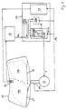
- a sensor device 12 is arranged in the wiping area 10a, as it is known from DE-GM 93 09 837. So far with respect to this sensor device largely on this document to get expelled. If necessary, however, the details of the sensor device in the following.
- the sensor device 12 is used during a wiping operation Wiper 11 in the wiping area of the Wipers swept twice.
- the sensor device is influenced by a coating or wetting of the pane that any influence is a signal Es analogous to the drop size or quantity generated.
- a signal processing device 13 is coupled, which the of the sensor device 12 generated signals in control signals S for formed the drive motor M.
- the facility can also be a Have switch contact device, which may have at least one specific Be assigned to the position of the wiper during the wiping process can. Usually acts it is in the switch contact device 14 around the motor limit switch of the drive motor M when it is actuated the wiper 11 is in its park position.
- the counter Z a counting arrangement 15 is provided.
- the counter counts all during a wipe from the Sensor device 12 determined signals and compares this with a preset certain value. On Exceeding this value triggers a wiping process out. However, the trigger value is larger than the number of signals from the sensor device 12 while sweeping the wiper be generated. After triggering the following wiping process, but at the latest after at least one Wipe cycle, the signal centering counter Z is on reset an initial value. Signal can too give a switch contact device 14 as soon as the Wipers e.g. is in its park position.
- the sensor device itself works optoelectronic, whereby through an interaction of radiation transmitters and radiation receivers formed at least two measuring sections are alternately controlled by a clock become.
- An evaluation device 16 detects the clocked signals, the occurring signals over a time constant, as in DE-GM 93 09 837 described, be adjusted to 0. That’s it possible to block out even strong external radiation that signals arise that are only from the surface and the wetting of the disc 10 are dependent.
- Advantageous is the ability of the sensor device 12 to Generate signals analogous to drop size and quantity. Generate small droplets small signals, big drops big signals and at Movement in the wind even several signals, so that clearly recognize the quality and quantity of wetting leaves.
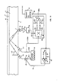
- the Switch arrangement for controlling the two radiation sources 2.1 and 2.2 a clock generator 30 to a non-inverting output 30.0 and at one inverting output 30.1 alternately one Current pulse each to excite the radiation of the radiation source connected to the output for generated the duration of the current pulse.
- One exit of the clock generator 30 contains for adjustment of the current value, a current actuator 32, which by a control signal Sr adjustable at its control input 47 is. The retroreflection of these two radiation sources at the coupling location of the radiation receiver 16 from this into an electrical output signal S 16 converted, corresponding to that shown in Fig.
- a signal centering stage 48 connected to the changes in the detection signal SD at the output of the filter circuit 36 one Center voltage Uz impresses.
- the signal centering stage 48 contains the signal centering stage 48 one Synchronous demodulator 49 with two demodulator outputs 49.1 and 49.2, each a radiation source assigned. The assignment is made via a Control clock S 30.0 of the current pulse generator 30, the also controls the radiation of the radiation sources.
- the demodulator outputs 49.1 and 49.2 are shown in the Embodiment demodulation value memory 50.1 and 50.2 downstream, which the mean amplitude value from that of the synchronous demodulator 49 sampled, the two radiation sources assigned signal sections of the demodulation signal Save SD currently and this way form an envelope demodulator. From the current mean amplitude values of the two detection value memories will be in a subsequent Operational amplifier 51 the difference value is formed and imprinted with a mean value.
- This so educated smoothed detection signal SD m which compared to the Detection signal SD at the output of the filter circuit 36 is substantially free from interference, both an evaluation arrangement 41 and a control circuit 52 supplied with a high control time constant Tv.
- the Control circuit a time constant element 53 and one Comparator 54, which is the comparison with a reference signal Sref a control signal Sr for the control input 47 of the current actuator 32 generated such that the Radiant power of the regulated with the current actuator Radiation source 2.1 is changed so that the Difference in the detection amplitude values at the output the signal centering stage 48 goes to zero.
- the Control speed i.e. the control time constant Tv the control circuit 52 is dimensioned so that it is significantly greater than the slowest Changes to be recorded in a Wetting process.
- the evaluation arrangement 41 can on the input side also directly with the output of the connected to two detection value memories 50.1 and 50.2 be, especially if by means of the evaluation arrangement the wetting is to be measured.
- the control time constant is a significant multiple is greater than an oscillation period of the Switching sequence signal that the radiation receiver assigned radiation sources or groups of Radiation sources switches. This will make it slower or permanent changes in the sensor active Area of the plate or wall that is not affected by the wetting are caused or do not affect wetting, not when recognizing or measuring the wetting takes into account and influences due to aging, pollution or temperature differences the known systems problems are easily eliminated prepare.
- the values determined by the counter Z can then directly fed to a digital-to-analog converter 19 the control signals S for the drive motor M forms.
- the automatic Reset either time-dependent, control voltage-dependent or depending on the wiper position, individually occurring signals are also reliably determined. It becomes the integer Distance between the initial value A and the trigger value if it is exceeded, the wiping process is triggered is increased compared to the value corresponding to the number of Sweeping, e.g. corresponds to the number 1 or 2.
- the first signal can then e.g.
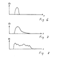
- the clear detection possibility of the Signals causes a single event, such as the An insect encountered according to FIG. 6 is a clear one Single signal results while a drop and especially a drop in the wind according to the fig. 7 and 8 longer or more signals generated the counter have them count up accordingly so that the preset Trigger value is exceeded. An unexpected release and related moments of shock of the Drivers are avoided.
- Setting means 18 can be provided for regulating the response behavior of the sensor device 12. These setting means 18 can also be arranged directly on the sensor device and reduce the response behavior of the sensor device as a function of the motor signal Ms of the switch contact device 14 after a predetermined time t v after the start of a wiping process. This leads to a shift in the value from which the existing signals are detected become. Regulating courses can thus be formed within the individually present signals, which already change the signals corresponding to the drops for evaluation purposes. The detection threshold is shifted within usable signals. As a result, large drops lead to an input signal due to the level and / or duration of the signal with reduced response, while smaller droplets have no effect.
- the setting means 18 for regulating the response behavior of the device the response behavior after a predetermined time t v , which may also be zero and after which the wiper 11 has left its parking position or after which the control signal has been transmitted to the wiper is to regulate from an initial state with sensitive response to a predetermined intermediate state with insensitive response and then regulate back to a final state within a certain time t 2 , which preferably corresponds to the initial state.
- a signal from the limit switch may also be dispensed with.
- a regulation of the determined signals in the sensor always takes place via the control time constant so that the difference value of the signal goes to zero, with a long control time constant the difference value goes slower to zero than a short one Control time constant.
- the setting means 18 regulate the control time constant during a wiping process shorter than at a time when none Wetting is present. That alone is the reason possible changes caused by self-drying Streaks appear after wiping off hide the measurement signals.
- the control time constant is processed by the signal processing device 13 depending on the signal from the motor limit switch and a period of about 10-30 seconds regulated. This shifts the sensitivity so that only large drops can be recognized after returning. As a side effect, one gets overpainted the sensor device 12 through the wiper 11 generated signal can be evaluated, because with a lot of rain too a large wipe pulse is generated.
- adjusting means a can also be provided which, depending on a signal from the switching contact device 14, reduce a division ratio within a predetermined time t 2 to 1: 1, so that initially a plurality of signals Es lead to a single signal until the adjusting means 30 a have set the divisor to 1.
- a signal from the switching contact device 14 reduces a division ratio within a predetermined time t 2 to 1: 1, so that initially a plurality of signals Es lead to a single signal until the adjusting means 30 a have set the divisor to 1.
- Fig. 2a first shows the motor signal Ms, which changes over time. As soon as the windshield wiper motor is switched on at time t 1 , a motor signal Ms results which is present over the wiping period t w . The occurrence of this motor signal ensures that the value of the counter Z is set to the initial value A, which is minus 2 according to FIG. 2c. The number minus 2 is then chosen because the wiper 11 sweeps twice over the sensor device 12 in the wiping area 10a. In FIG. 2b, signals that have occurred over time are also recorded. The first two signals 20 and 21 are caused by the wiper sweeping over the sensor device.
- Each signal leads to a pulse as an input signal Es in the signal processing device 13.
- the counting arrangement 15 counts up to the value 0 solely by these two signals, which corresponds to the preset specific value.
- the two further occurring signals 22 then further increase this value, so that depending on the value of the counter Z, the digital-to-analog converter 19 now generates control signals S for the drive motor, which in turn lead to the wiper being switched on, which resets the counter to the initial value minus 2.
- This counting arrangement 15 can be used together with a sensitivity control, as can be seen in FIGS. 3a to 5 results.
- the examples show a control of the sensitivity, i.e. a reduction in the amplitude.
- changing the control time constant or the divider ratio has a similar effect.
- 3a shows the motor signal which, at time t 1, regulates the sensitivity E according to FIG. 3b from a maximum value E max to a minimum value E min via the setting means 18 for regulating the response behavior.
- this minimum value is initially maintained over a predetermined time t v .
- the sensitivity E is gradually converted back to the value E max .
- the sensitivity that is to say the response behavior of the entire sensor device, is changed in a controlled manner according to the dashed line. Signals lead to a reaction of the control as soon as the detection threshold is exceeded, whereby several signals can also be stored in a memory in order to achieve a smooth, even wiping process.
- a rain sets in on the left side of FIG. 5, which triggers a wiping at the peak P1, since the detection threshold is exceeded.
- the vehicle user would also have operated his wiper now because of the visual impairment.
- t v 0, the sensitivity at the beginning of the wiping process, that is to say at time t 1 , is reduced from the initial state to an intermediate state.
- the following drops appear smaller in amplitude. If it is heavy rain, they would still reach detection threshold D again immediately.
- the sensitivity gradually increases again and would reach a final state of maximum sensitivity E max which corresponds to the initial state if a drop as peak P2 did not exceed the detection threshold.
- E max maximum sensitivity
- the sensitivity immediately falls to the intermediate state of minimal sensitivity E min .
- the control registers the time between the peaks or between the reduction in sensitivity as the next wiping interval with the interval time ti 1 .
- the changing conditions during a rain would be taken into account by the fact that if the second peak had already reached the detection threshold earlier, for example the peak P 3 shown in broken lines, the interval time ti 2 would have resulted.
- the counting arrangement 15 can be a first storage unit be that when a predetermined one is exceeded Value V and / or after a predetermined number of successive, if necessary, within a certain time Wiping over signal transmission means further signals Sw to a background memory 25 transmits, the content of which also generates Control signals, if necessary, even after the storage unit has been discharged affected.
- a predetermined threshold V here additionally or alternatively also the number of immediately consecutive wiping operations can be. Is the value V exceeded or the value of the background memory 25 is reached increased, preferably a value is selected that is less than the total content of the memory by one flexible behavior of this background memory too achieve. For example, the value can be increased by 2. In a subsequent step then becomes this value e.g. decreased by 1 as soon as a signal from the switch contact device is given.
- This background memory 25 is a gradual one Tracking of wiping movements possible, since rain does not start suddenly in nature and stops, so that a regular wiping is achieved after a rain.
- the storage unit operating in the foreground, here the counting arrangement reacts to splash water in a flash.
- the control unit learns that there is a corresponding wetting which requires another wipe makes. However, this trigger value is reached before the previous one Wiping is finished is one Wetting that the wiper in the Continuous operation must remain. In this respect, this leads to premature reaching the trigger values again for such a e.g. Extension of the control signal (S) that the Drive motor (M) remains in continuous operation. This can e.g. the time during which the control voltage is applied accordingly to be influenced.
Landscapes
- Physics & Mathematics (AREA)
- Life Sciences & Earth Sciences (AREA)
- General Physics & Mathematics (AREA)
- Chemical & Material Sciences (AREA)
- Pathology (AREA)
- Analytical Chemistry (AREA)
- Biochemistry (AREA)
- General Health & Medical Sciences (AREA)
- Health & Medical Sciences (AREA)
- Immunology (AREA)
- Engineering & Computer Science (AREA)
- Mathematical Physics (AREA)
- Automation & Control Theory (AREA)
- Mechanical Engineering (AREA)
- General Life Sciences & Earth Sciences (AREA)
- Geophysics (AREA)
- Control Of Direct Current Motors (AREA)
- Control Of Non-Electrical Variables (AREA)
- Vehicle Cleaning, Maintenance, Repair, Refitting, And Outriggers (AREA)
Description
- Fig. 1
- eine schematische Schaltungsanordnung der Einrichtung zur Steuerung einer Scheibenwischanlage,
- Fig. 2a,2b,2c
- Diagramme des Motorsignals, des Eingangssignals und der Zählerstellung über die Zeit,
- Fig. 3a,3b
- Diagramme des Motorsignals und der Empfindlichkeit über die Zeit,
- Fig. 4
- ein Diagramm der Empfindlichkeit über die Zeit bei tv=0,
- Fig. 5
- ein Diagramm der Eingangssignale über die Zeit,
- Fig. 6-8
- Diagramme, bei denen der Wert eines Eingangssignals über die Zeit aufgetragen ist, bei Auftreffen eines Insekts, bei Auftreffen eines Wassertropfens und bei Auftreten eines im Wind bewegten Wassertropfens,
- Fig. 9
- einen Ablaufplan für die Arbeit mit einem Hintergrundspeicher,
- Fig. 10
- ein Blockschaltbild der Sensorvorrichtung.
Claims (12)
- Einrichtung zur Steuerung einer Scheibenwischanlage mitdadurch gekennzeichnet, dasseinem Antriebsmotor (M) für wenigstens einen, einen Wischbereich (10a) einer Scheibe (10) überstreichenden Wischer (11),einer im Wischbereich (10a) angeordneten Sensorvorrichtung (12), die während eines Wischvorgangs vom Wischer (11) zweimal überstrichen wird und Signale vermittelt, die vom Belag oder der Benetzung der Scheibe (10) beeinflußt sind,einer mit Antriebsmotor (M) und Sensorvorrichtung (12) gekoppelten Signalverarbeitungseinrichtung (13), die die von der Sensorvorrichtung (12) vermittelten Signale (Es) in Steuersignale (S) für den Antriebsmotor (M) umformt,einer Auswertevorrichtung (16), die die Signale der Sensorvorrichtung (12) detektiert und der Signalverarbeitungseinrichtung (13) zuführt,einer Zählanordnung (15), deren Zähler (Z) die während eines Wischvorgangs von der Sensorvorrichtung (12) vermittelten Signale (Es) zählt, wobei ein Überschreiten eines bestimmten Wertes des Zählers (Z) einen weiteren Wischvorgang auslöst, wobei der Zähler (Z) selbstätig auf einen Ausgangswert rückstellbar ist,der Zähler (Z) selbst das einzige Mittel zur Erkennung der vom Überstreichen des Wischers hervorgerufenen einzelnen Signale ist,der Auslösewert größer ist als die Anzahl der Signale, die von der Sensorvorrichtung (12) allein dadurch erzeugt werden, daß der Wischer (11) selbst die Sensorvorrichtung (12) überstreicht, wobei der ganzzahlige Abstand zwischen dem Ausgangswert und dem bestimmten Wert größer zwei ist,die optoelektronische Sensorvorrichtung (12) mehrere Strahlungssender und wenigstens einen Strahlungsempfänger oder wenigstens einen Strahlungssender und mehrere Strahlungsempfänger aufweist, die wenigstens zwei Meßstrecken bilden, die über einen Taktgeber wechselweise angesteuert werden, und daß die Auswertevorrichtung (16) die einzelnen getakteten Signale detektiert und der Signalverarbeitungseinrichtung (13) zuführt, wobei eine Einstellanordnung (32) zur Einstellung einer derart bemessenen Strahlungsleistung der einzelnen Strahlungsquellen vorgesehen ist, daß bei unbenetztem sensoraktivem Bereich jede Meßstrecke einen Abschnitt des Detektionssignals erzeugt, dessen mittlerer Amplitudenwert gleich dem mittleren Amplitudenwert der den anderen Meßstrecken zugeordneten Abschnitte des Detektionssignals ist, und wobei eine Signalzentrierstufe (48) das getaktete Detektionssignal hinsichtlich des Unterschieds zwischen den den einzelnen Meßstrecken zugeordneten Abschnitten zur Erzeugung eines Steuersignals filtert.
- Einrichtung nach Anspruch 1, dadurch gekennzeichnet, daß bei Erreichen des bestimmten Wertes des Zählers (Z) ein weiterer Wischvorgang gestartet wird und daß, wenn der bestimmte Wert vor Ende des vorausgehenden Wischvorgangs erreicht wird, das Steuersignal (S) so erzeugt wird, daß der Antriebsmotor (M) im Dauerbetrieb bleibt.
- Einrichtung nach Anspruch 1, dadurch gekennzeichnet, daß ein Motorendschalter des Antriebsmotors (M), bei dessen Betätigung der Wischer (11) in seiner Parkstellung ist, den Zähler (Z) zurückstellt.
- Einrichtung nach Anspruch 1, dadurch gekennzeichnet, daß der ganzzahlige Abstand zwischen Ausgangswert (A) und dem Auslösewert, dessen Überschreiten den Wischvorgang auslöst, um wenigstens 1 größer ist als die Anzahl der Signale, die der Wischer (11) beim Überstreichen der Sensorvorrichtung (12) erzeugt.
- Einrichtung nach Anspruch 4, dadurch gekennzeichnet, daß ein erstes Signal einen Timer (17) schaltet, der den Ausgangswert für einen voreinstellbaren Zeitraum um wenigstens 1 erhöht, wobei jedes neu eintreffende Signal ebenfalls über den Timer geführt wird und die Timerlaufzeit neu startet.
- Einrichtung nach Anspruch 1, dadurch gekennzeichnet, daß die Sensorvorrichtung (12) Signale analog zur Tropfengröße und - anzahl erzeugt und daß Einstellmittel (18) zur Regelung des Ansprechverhaltens der Einrichtung vorgesehen sind, die das Ansprechverhalten nach einer vorgegebenen Zeit (tv), nach der der Wischer (11) gestartet ist, von einem Ausgangszustand mit empfindlichem Ansprechverhalten auf einen vorbestimmten Zwischenzustand mit unempfindlichem Ansprechverhalten regeln und anschließend innerhalb einer bestimmten Zeit (t2) auf einen Endzustand mit empfindlichen Ansprechverhalten zurückregeln, der vorzugsweise dem Ausgangszustand entspricht.
- Einrichtung nach Anspruch 6, dadurch gekennzeichnet, daß die Einstellmittel (18) zur Regelung des Ansprechverhaltens das Ansprechverhalten vor Erreichen des Ausgangszustands wieder auf den Zwischenzustand verringern, wenn die Signale (Es) eine Detektionsschwelle überschreiten, und daß die Zeit zwischen dem ersten und dem zweiten Erreichen des Zwischenzustands bei tv=0 die Intervallzeit (ti) des Wischers ist.
- Einrichtung nach Anspruch 6, dadurch gekennzeichnet, daß die Einstellmittel (18) zur Regelung des Ansprechverhaltens das Ansprechverhalten und die Empfindlichkeit der Sensorvorrichtung durch Verringerung der Verstärkung der Signale regeln und/oder durch Verringerung der Regelzeitkonstante regeln, innerhalb der auftretende Signale (Es) ausgeregelt werden.
- Einrichtung nach Anspruch 6, dadurch gekennzeichnet, daß die Einstellmittel (18) zur Regelung des Ansprechverhaltens Stellmittel (30) umfassen, die ein Teilerverhältnis innerhalb der bestimmten Zeit (t2) bis auf 1:1 verringern, so daß zunächst mehrere Signale (Es) zu einem einzigen Signal führen, bis die Stellmittel (30) den Teiler auf 1 gesetzt haben.
- Einrichtung nach Anspruch 1, dadurch gekennzeichnet, daß die Zählanordnung (15) eine erste Speichereinheit ist und daß bei Überschreiten eines vorgegebenen weiteren Wertes (V) und/oder nach einer vorgegebenen Anzahl von ggf. innerhalb einer bestimmten Zeiteinheit aufeinanderfolgenden Wischvorgängen Signalubertragungsmittel weitere Signale (Sw) an einen Hintergrundspeicher (25) übertragen, dessen Inhalt ebenfalls die Erzeugung von Steuersignalen ggf. auch nach Entladen der Speichereinheit beeinflußt.
- Einrichtung nach Anspruch 10, dadurch gekennzeichnet, daß, sobald der weitere Wert oder die Anzahl von Wischvorgängen überschritten ist, die Signalübertragungsmittel einen begrenzten Signalwert (Y) in den Hintergrundspeicher (25) übertragen, der kleiner ist als sein maximaler Speicherinhalt.
- Einrichtung nach Anspruch 10, dadurch gekennzeichnet, daß der Wert (w) des digitalen Hintergrundspeichers (25) mit jedem erfolgtem Wischvorgang um einen vorgegebenen dritten Wert bis zur vollständigen Entladung verringert wird.
Applications Claiming Priority (7)
| Application Number | Priority Date | Filing Date | Title |
|---|---|---|---|
| DE9309837U DE9309837U1 (de) | 1993-07-02 | 1993-07-02 | Anordnung zum Messen oder Erkennen der Benetzung einer für eine bestimmte Strahlung durchlässigen Wand oder Platte |
| DE9309837U | 1993-07-02 | ||
| DE4403221A DE4403221A1 (de) | 1993-07-02 | 1994-02-03 | Anordnung zum Messen oder Erkennen einer Veränderung an einem rückstrahlenden Element |
| DE4403221 | 1994-02-03 | ||
| DE4411772A DE4411772A1 (de) | 1993-07-02 | 1994-04-06 | Einrichtung zur Steuerung einer Scheibenwischanlage |
| DE4411772 | 1994-04-06 | ||
| PCT/DE1994/000710 WO1995001270A1 (de) | 1993-07-02 | 1994-06-18 | Einrichtung zur steuerung einer scheibenwischanlage |
Publications (3)
| Publication Number | Publication Date |
|---|---|
| EP0705186A1 EP0705186A1 (de) | 1996-04-10 |
| EP0705186B1 EP0705186B1 (de) | 1997-03-12 |
| EP0705186B2 true EP0705186B2 (de) | 2002-09-11 |
Family
ID=27206041
Family Applications (1)
| Application Number | Title | Priority Date | Filing Date |
|---|---|---|---|
| EP94918290A Expired - Lifetime EP0705186B2 (de) | 1993-07-02 | 1994-06-18 | Einrichtung zur steuerung einer scheibenwischanlage |
Country Status (6)
| Country | Link |
|---|---|
| US (1) | US5726547A (de) |
| EP (1) | EP0705186B2 (de) |
| JP (1) | JPH09500345A (de) |
| AU (1) | AU6968394A (de) |
| ES (1) | ES2102230T5 (de) |
| WO (1) | WO1995001270A1 (de) |
Families Citing this family (18)
| Publication number | Priority date | Publication date | Assignee | Title |
|---|---|---|---|---|
| US6118383A (en) * | 1993-05-07 | 2000-09-12 | Hegyi; Dennis J. | Multi-function light sensor for vehicle |
| KR19990063055A (ko) * | 1997-12-17 | 1999-07-26 | 마쯔무라 미노루 | 물방울 감응식 와이퍼 제어장치 |
| DE19815746C1 (de) * | 1998-04-08 | 1999-11-04 | Bosch Gmbh Robert | Sensoreinrichtung zur Erfassung einer Benetzung auf einer Scheibe |
| DE19842064A1 (de) * | 1998-09-15 | 2000-03-16 | Bosch Gmbh Robert | Vorrichtung zur automatischen Ansteuerung einer Einrichtung |
| JP2002123304A (ja) * | 2000-10-13 | 2002-04-26 | Yazaki Corp | 機能選択制御システム |
| SE0101555D0 (sv) * | 2001-05-04 | 2001-05-04 | Amersham Pharm Biotech Ab | Fast variable gain detector system and method of controlling the same |
| DE102004010492A1 (de) | 2004-03-04 | 2005-09-22 | Robert Bosch Gmbh | Regensensor, insbesondere für ein Kraftfahrzeug |
| JP4779860B2 (ja) * | 2006-08-03 | 2011-09-28 | 株式会社デンソー | 雨滴量検出装置及びワイパー制御装置 |
| US7679304B2 (en) * | 2006-09-08 | 2010-03-16 | Hasenberg, Inc. | Intermittent wiper control device |
| FR2937128B1 (fr) * | 2008-10-14 | 2010-12-31 | Continental Automotive France | Dispositif de detection d'un parametre d'environnement |
| FR2932258A1 (fr) * | 2008-10-14 | 2009-12-11 | Continental Automotive France | Dispositif de detection d'un parametre d'environnement |
| JP2012509472A (ja) * | 2008-11-20 | 2012-04-19 | エルモス セミコンダクター エーゲー | 干渉補正可能なセンサ |
| JP2011122870A (ja) * | 2009-12-09 | 2011-06-23 | Seiko Epson Corp | 光学式位置検出装置及び投射型表示装置 |
| JP2011122867A (ja) * | 2009-12-09 | 2011-06-23 | Seiko Epson Corp | 光学式位置検出装置および位置検出機能付き表示装置 |
| JP5741088B2 (ja) | 2011-03-14 | 2015-07-01 | セイコーエプソン株式会社 | 位置検出システム及び投射型表示システム |
| CN105300705B (zh) * | 2015-10-08 | 2017-08-25 | 上汽大众汽车有限公司 | 雨刮器试验装置 |
| FR3050889A1 (fr) * | 2016-04-27 | 2017-11-03 | STMicroelectronics (Alps) SAS | Circuit d'emission optique en creneaux |
| EP3741630B1 (de) | 2019-05-21 | 2024-04-10 | TE Connectivity Sensors France | Echtzeitfeinanpassung eines treiberstroms einer lichtemittierenden vorrichtung eines optischen regensensors |
Family Cites Families (48)
| Publication number | Priority date | Publication date | Assignee | Title |
|---|---|---|---|---|
| US216341A (en) * | 1879-06-10 | Improvement in combined spring and dead bolts | ||
| DE2200878A1 (de) * | 1972-01-08 | 1973-08-23 | Licentia Gmbh | Lichtschranke |
| CH568627A5 (de) * | 1974-07-15 | 1975-10-31 | Cerberus Ag | |
| DE2630470A1 (de) * | 1976-07-07 | 1978-01-12 | Schmidt Karl Heinz | Selbsttaetige steuerung von kraftfahrzeug-scheibenwischanlagen |
| DE3140865A1 (de) * | 1981-10-14 | 1983-05-11 | Hans-Wolfgang 8000 München Diesing | Schaltungsanordnung fuer gepulste reflexionslichtschranken |
| DK146959C (da) * | 1981-12-08 | 1984-08-06 | Boeegh Petersen Allan | Viskerrobot med foeler |
| DE3203091C2 (de) * | 1982-01-30 | 1985-06-13 | Vdo Adolf Schindling Ag, 6000 Frankfurt | Einrichtung zum Steuern der Scheibenreinigungsanlage eines Kraftfahrzeugs |
| DE3218279A1 (de) * | 1982-05-13 | 1983-11-17 | Manfred 1000 Berlin Lau | Automatischer intervallschalter fuer scheibenwischer |
| US4527105A (en) * | 1982-09-02 | 1985-07-02 | Nissan Motor Company, Limited | Automatic windshield wiper speed control with piezoelectric sensor |
| DE3235590C2 (de) * | 1982-09-25 | 1984-11-22 | Fraunhofer-Gesellschaft zur Förderung der angewandten Forschung e.V., 8000 München | Vorrichtung zum optischen Erfassen von Fremdkörpern |
| JPS59140146A (ja) * | 1983-01-28 | 1984-08-11 | Jidosha Denki Kogyo Co Ltd | ワイパ間欠駆動制御装置 |
| DE3314770A1 (de) * | 1983-04-23 | 1984-10-31 | Sidler GmbH & Co, 7400 Tübingen | Einrichtung zum steuern eines scheibenwischermotors |
| JPS6111637A (ja) * | 1984-06-27 | 1986-01-20 | Nec Corp | 液体センサ |
| US4620141A (en) * | 1985-07-03 | 1986-10-28 | Vericom Corp. | Rain-controlled windshield wipers |
| DE3619208A1 (de) * | 1986-06-07 | 1987-12-10 | Bosch Gmbh Robert | Vorrichtung zum optischen erfassen von fremdkoerpern |
| US4867561A (en) * | 1986-08-22 | 1989-09-19 | Nippondenso Co., Ltd. | Apparatus for optically detecting an extraneous matter on a translucent shield |
| DE3715798A1 (de) * | 1987-05-12 | 1988-01-07 | Erich Ing Grad Huber | Opto-elektronische einrichtung zum erkennen von verschmutzung transparenter schutzscheiben und ausloesen der reinigungsmassnahmen |
| DE3722510A1 (de) * | 1987-07-08 | 1989-01-26 | Bosch Gmbh Robert | Vorrichtung zum regenabhaengigen ein- und ausschalten eines elektrischen scheibenwischermotors |
| IT212441Z2 (it) * | 1987-07-31 | 1989-07-04 | Veglia Borletti Srl | Dispositivo sensore della presenza di gocce di acqua su un cristallo di un veicolo e apparecchiatura dicomando di un tergicristallo provvista del detto dispositivo |
| IT212332Z2 (it) * | 1987-07-31 | 1989-07-04 | Veglia Borletti Srl | Dispositivo sensore della presenza di gocce d acqua su un cristallo di un veicolo e apparecchiatura dicomando di un tergicristallo provvista del detto dispositivo |
| DE3733762A1 (de) * | 1987-10-06 | 1989-04-20 | Karl Gerhard | Scheibenverschmutzungsmelder |
| DE3800327A1 (de) * | 1988-01-08 | 1989-07-27 | Bosch Gmbh Robert | Verfahren zum betreiben eines scheibenwischers und vorrichtung zur durchfuehrung des verfahrens |
| JPH0238167A (ja) * | 1988-07-29 | 1990-02-07 | Stanley Electric Co Ltd | 雨滴検出装置 |
| US4942349A (en) * | 1988-10-14 | 1990-07-17 | Millerd Donald L | Control system for operating a window wiper in response to water moisture |
| US5057754A (en) * | 1988-10-14 | 1991-10-15 | Mist-Defy'r, Inc. | Moisture-sensing window cleaning control system |
| DE3941905A1 (de) * | 1988-12-19 | 1990-06-21 | Fujitsu Ten Ltd | Scheibenwischersteuervorrichtung |
| US4960996A (en) * | 1989-01-18 | 1990-10-02 | Hochstein Peter A | Rain sensor with reference channel |
| JP2723355B2 (ja) * | 1989-01-26 | 1998-03-09 | エタブリッセメント・ボラルプ | 自動車用アクセサリのための駆動機構制御装置 |
| DE3902231A1 (de) * | 1989-01-26 | 1990-08-09 | Voralp Ets | Einrichtung fuer die steuerung eines scheibenwischers |
| US4956591A (en) * | 1989-02-28 | 1990-09-11 | Donnelly Corporation | Control for a moisture sensor |
| US4916374A (en) * | 1989-02-28 | 1990-04-10 | Donnelly Corporation | Continuously adaptive moisture sensor system for wiper control |
| FR2648096B1 (fr) * | 1989-06-12 | 1991-08-23 | Valeo Systemes Dessuyage | Systeme d'essuie-glace avec detecteur de pluie |
| DE3935807A1 (de) * | 1989-10-27 | 1991-05-02 | Swf Auto Electric Gmbh | Wischanlage fuer kraftfahrzeuge |
| US5059877A (en) * | 1989-12-22 | 1991-10-22 | Libbey-Owens-Ford Co. | Rain responsive windshield wiper control |
| DE4000736A1 (de) * | 1990-01-12 | 1991-07-18 | Vdo Schindling | Verfahren und anordnung zur steuerung eines scheibenwischers |
| DE4000735A1 (de) * | 1990-01-12 | 1991-07-18 | Vdo Schindling | Verfahren und anordnung zur steuerung eines scheibenwischers |
| DE4018903A1 (de) * | 1990-06-13 | 1991-12-19 | Bosch Gmbh Robert | Vorrichtung zum betreiben eines scheibenwischers |
| US5252898A (en) * | 1990-06-13 | 1993-10-12 | Robert Bosch Gmbh | Method of operating a windshield wiper |
| DE4036407C2 (de) * | 1990-11-15 | 1994-06-01 | Telefunken Microelectron | Sensorsystem |
| DE4120750A1 (de) * | 1991-06-24 | 1993-01-07 | Kostal Leopold Gmbh & Co Kg | Einrichtung zur steuerung einer scheibenwischanlage |
| DE4217390C2 (de) * | 1991-06-24 | 1994-06-16 | Kostal Leopold Gmbh & Co Kg | Einrichtung zur Steuerung einer Scheibenwischanlage |
| DE4134432A1 (de) * | 1991-10-18 | 1993-04-22 | Daimler Benz Ag | Verfahren zur anpassung der ansprechempfindlichkeit eines niederschlagssensorsystems an umgebungsverhaeltnisse und sensorsystem mit einem niederschlagssensor |
| DE4141348C3 (de) * | 1991-12-14 | 1999-04-29 | Kostal Leopold Gmbh & Co Kg | Einrichtung zur Steuerung einer Scheibenwischanlage |
| DE4231763C2 (de) * | 1992-09-23 | 1995-07-06 | Kostal Leopold Gmbh & Co Kg | Einrichtung zur Steuerung einer Scheibenwischanlage |
| DE4209680A1 (de) * | 1992-03-25 | 1993-09-30 | Bosch Gmbh Robert | Regensensor |
| DE4229491A1 (de) * | 1992-09-04 | 1993-01-07 | Steinbacher Peter Dipl Ing Fh | Vorrichtung zur steuerung einer scheibenwischeranlage fuer kraftfahrzeuge |
| DE9309837U1 (de) * | 1993-07-02 | 1993-09-02 | Reime, Gerd, 75328 Schömberg | Anordnung zum Messen oder Erkennen der Benetzung einer für eine bestimmte Strahlung durchlässigen Wand oder Platte |
| DE4403661A1 (de) * | 1994-02-05 | 1995-08-10 | Bosch Gmbh Robert | Vorrichtung zum Betreiben eines Scheibenwischers im Intervall- und Dauerbetrieb |
-
1994
- 1994-06-18 AU AU69683/94A patent/AU6968394A/en not_active Abandoned
- 1994-06-18 US US08/578,683 patent/US5726547A/en not_active Expired - Lifetime
- 1994-06-18 WO PCT/DE1994/000710 patent/WO1995001270A1/de not_active Ceased
- 1994-06-18 ES ES94918290T patent/ES2102230T5/es not_active Expired - Lifetime
- 1994-06-18 EP EP94918290A patent/EP0705186B2/de not_active Expired - Lifetime
- 1994-06-18 JP JP7503209A patent/JPH09500345A/ja active Pending
Also Published As
| Publication number | Publication date |
|---|---|
| ES2102230T3 (es) | 1997-07-16 |
| WO1995001270A1 (de) | 1995-01-12 |
| EP0705186A1 (de) | 1996-04-10 |
| US5726547A (en) | 1998-03-10 |
| JPH09500345A (ja) | 1997-01-14 |
| EP0705186B1 (de) | 1997-03-12 |
| ES2102230T5 (es) | 2003-05-01 |
| AU6968394A (en) | 1995-01-24 |
Similar Documents
| Publication | Publication Date | Title |
|---|---|---|
| DE4411770C2 (de) | Einrichtung zur Steuerung einer Scheibenwischanlage | |
| EP0705186B2 (de) | Einrichtung zur steuerung einer scheibenwischanlage | |
| EP0706648B1 (de) | Anordnung zum messen oder erkennen einer veränderung an einem rückstrahlenden element | |
| DE69011100T2 (de) | Auf regen reagierende scheibenwischersteuerung. | |
| DE4036407C2 (de) | Sensorsystem | |
| EP0547337B1 (de) | Einrichtung zur Steuerung einer Scheibenwischanlage | |
| DE4339574C2 (de) | Auswertevorrichtung für Signale, die von einer Meßanordnung zum Messen oder Erkennen einer Benetzung einer Fläche ermittelt wurden | |
| DE19526249A1 (de) | Vorrichtung zur Erfassung von Wasser oder dergleichen auf einer Fensterscheibe eines Kraftfahrzeuges | |
| DE3244767A1 (de) | Scheibenreinigungsanlage fuer kratfahrzeuge | |
| EP0770010B1 (de) | Vorrichtung zum betreiben eines scheibenwischers | |
| EP0720547B1 (de) | Einrichtung für die automatische steuerung eines scheibenwischermotors | |
| DE4231763A1 (de) | Einrichtung zur Steuerung einer Scheibenwischanlage | |
| DE10214421A1 (de) | Verfahren zum Betreiben eines Regensensors, insbesondere für Kraftfahrzeuge | |
| DE19536621C2 (de) | Vorrichtung zur elektronischen Steuerung eines Scheibenwischers bei Kraftfahrzeugen | |
| EP1398230A2 (de) | Regensensor insbesondere für ein Kraftfahrzeug mit einer Scheibenwischvorrichtung sowie Verfahren zum Steuern einer Scheibenwischvorrichtung | |
| EP0827467B1 (de) | Vorrichtung zum betreiben eines scheibenwischers | |
| WO1996037387A1 (de) | Vorrichtung zum betreiben eines scheibenwischers | |
| EP1199231A2 (de) | Verfahren zur Steuerung einer Scheibenwischanlage | |
| DE102006000215B4 (de) | Einrichtung zur Steuerung einer Scheibenwischanlage eines Kraftfahrzeuges | |
| DE29508822U1 (de) | Vorrichtung zum Betreiben eines Scheibenwischers | |
| DE29508821U1 (de) | Vorrichtung zum Betreiben eines Scheibenwischers |
Legal Events
| Date | Code | Title | Description |
|---|---|---|---|
| PUAI | Public reference made under article 153(3) epc to a published international application that has entered the european phase |
Free format text: ORIGINAL CODE: 0009012 |
|
| 17P | Request for examination filed |
Effective date: 19951229 |
|
| AK | Designated contracting states |
Kind code of ref document: A1 Designated state(s): DE ES FR GB |
|
| GRAG | Despatch of communication of intention to grant |
Free format text: ORIGINAL CODE: EPIDOS AGRA |
|
| 17Q | First examination report despatched |
Effective date: 19960502 |
|
| GRAH | Despatch of communication of intention to grant a patent |
Free format text: ORIGINAL CODE: EPIDOS IGRA |
|
| GRAH | Despatch of communication of intention to grant a patent |
Free format text: ORIGINAL CODE: EPIDOS IGRA |
|
| GRAA | (expected) grant |
Free format text: ORIGINAL CODE: 0009210 |
|
| AK | Designated contracting states |
Kind code of ref document: B1 Designated state(s): DE ES FR GB |
|
| GBT | Gb: translation of ep patent filed (gb section 77(6)(a)/1977) |
Effective date: 19970313 |
|
| REF | Corresponds to: |
Ref document number: 59402089 Country of ref document: DE Date of ref document: 19970417 |
|
| ET | Fr: translation filed | ||
| REG | Reference to a national code |
Ref country code: ES Ref legal event code: FG2A Ref document number: 2102230 Country of ref document: ES Kind code of ref document: T3 |
|
| PLBQ | Unpublished change to opponent data |
Free format text: ORIGINAL CODE: EPIDOS OPPO |
|
| PLBI | Opposition filed |
Free format text: ORIGINAL CODE: 0009260 |
|
| PLBQ | Unpublished change to opponent data |
Free format text: ORIGINAL CODE: EPIDOS OPPO |
|
| PLBI | Opposition filed |
Free format text: ORIGINAL CODE: 0009260 |
|
| PLBI | Opposition filed |
Free format text: ORIGINAL CODE: 0009260 |
|
| 26 | Opposition filed |
Opponent name: AWS SYSTEM-VERWERTUNGS GMBH AUTOMATIC WIPER Effective date: 19971114 |
|
| PLBF | Reply of patent proprietor to notice(s) of opposition |
Free format text: ORIGINAL CODE: EPIDOS OBSO |
|
| 26 | Opposition filed |
Opponent name: MANNESMANN VDO AG Effective date: 19971202 Opponent name: AWS SYSTEM-VERWERTUNGS GMBH AUTOMATIC WIPER Effective date: 19971114 |
|
| 26 | Opposition filed |
Opponent name: ROBERT BOSCH GMBH Effective date: 19971212 Opponent name: MANNESMANN VDO AG Effective date: 19971202 Opponent name: AWS SYSTEM-VERWERTUNGS GMBH AUTOMATIC WIPER Effective date: 19971114 |
|
| PLBF | Reply of patent proprietor to notice(s) of opposition |
Free format text: ORIGINAL CODE: EPIDOS OBSO |
|
| PLAW | Interlocutory decision in opposition |
Free format text: ORIGINAL CODE: EPIDOS IDOP |
|
| APAC | Appeal dossier modified |
Free format text: ORIGINAL CODE: EPIDOS NOAPO |
|
| APAE | Appeal reference modified |
Free format text: ORIGINAL CODE: EPIDOS REFNO |
|
| APAC | Appeal dossier modified |
Free format text: ORIGINAL CODE: EPIDOS NOAPO |
|
| REG | Reference to a national code |
Ref country code: GB Ref legal event code: IF02 |
|
| APAC | Appeal dossier modified |
Free format text: ORIGINAL CODE: EPIDOS NOAPO |
|
| PLAW | Interlocutory decision in opposition |
Free format text: ORIGINAL CODE: EPIDOS IDOP |
|
| PUAH | Patent maintained in amended form |
Free format text: ORIGINAL CODE: 0009272 |
|
| STAA | Information on the status of an ep patent application or granted ep patent |
Free format text: STATUS: PATENT MAINTAINED AS AMENDED |
|
| 27A | Patent maintained in amended form |
Effective date: 20020911 |
|
| AK | Designated contracting states |
Kind code of ref document: B2 Designated state(s): DE ES FR GB |
|
| GBTA | Gb: translation of amended ep patent filed (gb section 77(6)(b)/1977) | ||
| ET3 | Fr: translation filed ** decision concerning opposition | ||
| REG | Reference to a national code |
Ref country code: ES Ref legal event code: DC2A Date of ref document: 20030124 Kind code of ref document: T5 |
|
| APAH | Appeal reference modified |
Free format text: ORIGINAL CODE: EPIDOSCREFNO |
|
| PGFP | Annual fee paid to national office [announced via postgrant information from national office to epo] |
Ref country code: FR Payment date: 20100706 Year of fee payment: 17 Ref country code: ES Payment date: 20100628 Year of fee payment: 17 |
|
| PGFP | Annual fee paid to national office [announced via postgrant information from national office to epo] |
Ref country code: GB Payment date: 20100623 Year of fee payment: 17 |
|
| GBPC | Gb: european patent ceased through non-payment of renewal fee |
Effective date: 20110618 |
|
| REG | Reference to a national code |
Ref country code: FR Ref legal event code: ST Effective date: 20120229 |
|
| PG25 | Lapsed in a contracting state [announced via postgrant information from national office to epo] |
Ref country code: FR Free format text: LAPSE BECAUSE OF NON-PAYMENT OF DUE FEES Effective date: 20110630 |
|
| PG25 | Lapsed in a contracting state [announced via postgrant information from national office to epo] |
Ref country code: GB Free format text: LAPSE BECAUSE OF NON-PAYMENT OF DUE FEES Effective date: 20110618 |
|
| REG | Reference to a national code |
Ref country code: ES Ref legal event code: FD2A Effective date: 20130405 |
|
| PG25 | Lapsed in a contracting state [announced via postgrant information from national office to epo] |
Ref country code: ES Free format text: LAPSE BECAUSE OF NON-PAYMENT OF DUE FEES Effective date: 20110619 |
|
| PGFP | Annual fee paid to national office [announced via postgrant information from national office to epo] |
Ref country code: DE Payment date: 20130628 Year of fee payment: 20 |
|
| REG | Reference to a national code |
Ref country code: DE Ref legal event code: R071 Ref document number: 59402089 Country of ref document: DE |