EP0704609B1 - Orosselklappengehäuse Fehlerbetätigung - Google Patents
Orosselklappengehäuse Fehlerbetätigung Download PDFInfo
- Publication number
- EP0704609B1 EP0704609B1 EP95202381A EP95202381A EP0704609B1 EP 0704609 B1 EP0704609 B1 EP 0704609B1 EP 95202381 A EP95202381 A EP 95202381A EP 95202381 A EP95202381 A EP 95202381A EP 0704609 B1 EP0704609 B1 EP 0704609B1
- Authority
- EP
- European Patent Office
- Prior art keywords
- air flow
- throttle
- throttle valve
- spring
- default
- Prior art date
- Legal status (The legal status is an assumption and is not a legal conclusion. Google has not performed a legal analysis and makes no representation as to the accuracy of the status listed.)
- Revoked
Links
Images


Classifications
-
- F—MECHANICAL ENGINEERING; LIGHTING; HEATING; WEAPONS; BLASTING
- F02—COMBUSTION ENGINES; HOT-GAS OR COMBUSTION-PRODUCT ENGINE PLANTS
- F02D—CONTROLLING COMBUSTION ENGINES
- F02D9/00—Controlling engines by throttling air or fuel-and-air induction conduits or exhaust conduits
- F02D9/02—Controlling engines by throttling air or fuel-and-air induction conduits or exhaust conduits concerning induction conduits
-
- F—MECHANICAL ENGINEERING; LIGHTING; HEATING; WEAPONS; BLASTING
- F02—COMBUSTION ENGINES; HOT-GAS OR COMBUSTION-PRODUCT ENGINE PLANTS
- F02D—CONTROLLING COMBUSTION ENGINES
- F02D11/00—Arrangements for, or adaptations to, non-automatic engine control initiation means, e.g. operator initiated
- F02D11/06—Arrangements for, or adaptations to, non-automatic engine control initiation means, e.g. operator initiated characterised by non-mechanical control linkages, e.g. fluid control linkages or by control linkages with power drive or assistance
- F02D11/10—Arrangements for, or adaptations to, non-automatic engine control initiation means, e.g. operator initiated characterised by non-mechanical control linkages, e.g. fluid control linkages or by control linkages with power drive or assistance of the electric type
- F02D11/107—Safety-related aspects
-
- F—MECHANICAL ENGINEERING; LIGHTING; HEATING; WEAPONS; BLASTING
- F02—COMBUSTION ENGINES; HOT-GAS OR COMBUSTION-PRODUCT ENGINE PLANTS
- F02D—CONTROLLING COMBUSTION ENGINES
- F02D9/00—Controlling engines by throttling air or fuel-and-air induction conduits or exhaust conduits
- F02D9/02—Controlling engines by throttling air or fuel-and-air induction conduits or exhaust conduits concerning induction conduits
- F02D2009/0201—Arrangements; Control features; Details thereof
- F02D2009/0269—Throttle closing springs; Acting of throttle closing springs on the throttle shaft
-
- F—MECHANICAL ENGINEERING; LIGHTING; HEATING; WEAPONS; BLASTING
- F02—COMBUSTION ENGINES; HOT-GAS OR COMBUSTION-PRODUCT ENGINE PLANTS
- F02D—CONTROLLING COMBUSTION ENGINES
- F02D9/00—Controlling engines by throttling air or fuel-and-air induction conduits or exhaust conduits
- F02D9/02—Controlling engines by throttling air or fuel-and-air induction conduits or exhaust conduits concerning induction conduits
- F02D2009/0201—Arrangements; Control features; Details thereof
- F02D2009/0277—Fail-safe mechanisms, e.g. with limp-home feature, to close throttle if actuator fails, or if control cable sticks or breaks
Definitions
- the invention relates to throttle body mechanisms for internal combustion engines.
- Electronically controlled throttle valves are contemplated for controlling the quantity of combustion air admitted to the intake manifold of internal combustion engines.
- These systems typically referred to in the automotive arts as electronic throttle control systems (ETC)
- ETC electronic throttle control systems
- ETC utilize an operator-actuated pedal position sensor which functions to transmit driver intent to an electronic actuator for positioning the throttle valve. It may be desirable to mechanically locate the throttle valve in a predetermined "default" position at times of actuator inoperativeness thereby assuring continued engine operation.
- a contemplated apparatus for default positioning of the throttle valve utilizes a throttle valve having a range of travel extending from a negative throttle plate position through a zero or minimum throttle plate position at which air flow through the throttle valve is minimized to a maximum or wide-open-throttle position in which air flow is maximized.
- the throttle plate is operated between the minimum and maximum air flow positions. Inoperativeness of the actuator allows a biasing member to move the throttle plate to the negative throttle plate position assuring a default quantity of air flow to the engine and, therefore, continued engine operation.
- the negative position throttle body referred to as an over-center design, involves costly manufacturing processes imposed by throttle bore/valve plate tolerances required to allow the throttle plate deflection through the zero or minimum air flow position.
- DE-U-9409891 discloses an air control valve having a pair of springs which impart a force on a throttle valve towards a default position of the valve when the valve is between a first, minimum air flow position and the default position; and a force on the throttle valve towards the default position when the valve is between a second, maximum air flow position and the default position.
- EP-A-0651147 which was published after the priority date of the present application, discloses an air control valve with a single spring acting on the throttle valve, and an actuator acting on the spring ends above first and second stop faces.
- An air control valve in accordance with the present invention is characterised by the features specified in Claim 1.
- the present invention discloses an air control valve or throttle body having a valve which is operated by an electronic throttle actuator between a minimum air flow position and a maximum air flow position.
- a default mechanism positions the throttle valve in a default position between the minimum and the maximum positions. In the default position, positive air flow through the valve allows continued engine operation.
- the air control valve includes a housing having an intake air passage or throttle bore in which is disposed a throttle valve.
- the throttle valve is rotatable between a minimum and a maximum position to thereby meter the quantity of air passing through the throttle bore and to the engine.
- a throttle shaft to which a throttle plate is attached, is driven by the electronic actuator to a desired location between the minimum and the maximum air flow positions. As mentioned above, a default position lies between the minimum and the maximum valve positions.
- a biasing member is operable on the throttle shaft at locations between the minimum air flow position and the default position and at locations between the default position and the maximum air flow position to return the throttle valve to the default position. Should the actuator become inoperative in this range of motion, the biasing member will return the valve to the default position.
- the throttle valve is biased towards a default position from all locations within it operating range.
- the bias of the throttle valve towards the default air flow position achieved with a single spring.
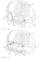
- an air control valve assembly designated generally as 10, is shown having a throttle body housing 12 with an air flow passage or throttle bore 14 extending therethrough.
- the throttle bore 14 conducts air to the intake system of an internal combustion engine (not shown).
- a throttle valve 16 which includes a throttle plate 18 attached to a shaft 20, is rotatably mounted within the throttle bore 14 of the throttle body housing 12.
- Bearings 22 support the throttle valve shaft 20 in the housing 12 and define a throttle valve axis 24 about which the valve 16 rotates to meter the flow of air through the throttle bore 14.
- Figure 3 illustrates the full range of motion of the throttle valve 16 in the bore 14.
- the valve is rotatably moveable from a minimum air flow position "A" to a maximum air flow position "B".
- Intermediate of the minimum and maximum throttle valve positions is a default position "C”.
- the default position "C" relates to a predetermined positive air flow which will allow continued engine operation should the actuating mechanism used to position the throttle valve become inoperative.
- an electronic actuator 26 Operably connected to the throttle shaft 20 is an electronic actuator 26.
- the actuator drives the throttle valve 16, based on operator input, to position the throttle valve between the minimum “A” and the maximum “B” air flow positions.
- the throttle body housing 12 includes a throttle return spring housing portion 28 which includes an inner wall 30 and a bottom 32 through which the end 34 of the throttle valve shaft 20 extends for attachment to the actuator 26.
- a biasing member such as spirally wound torsion spring 36 is disposed within the spring housing portion 28 of the throttle body housing 12.
- the spring 36 surrounds the end 34 of the throttle valve shaft 20 in a coaxial relationship therewith and includes first and second ends 38 and 40, respectively.
- Support for the spring coils may be provided by a bushing disposed between the throttle shaft 20 and the coils.
- the spring member 36 is rotationally preloaded within the spring housing 28 by rotating the spring ends 38,40 in opposite directions about the throttle valve axis 24 in the direction of the spring bias.
- the preload of spring 36 is maintained by allowing each spring end 38,40 to abut a stop 42 in the spring housing portion 28.
- the spring ends 38,40 abut opposite sides 44,46 of the housing stop 42 resulting in a spring force Fa being exerted on side 44 of the housing stop 42 in the counterclockwise direction, as viewed in the Figures, of rotation about axis 24, and a spring force Fb being exerted on side 46 of the housing stop 42 in the clockwise direction of rotation about axis 24.
- a spring actuating tang 48 depends from the throttle shaft 20 of the throttle valve 16 and is configured for positioning between the spring ends 38,40 in their positions against the housing stop 42; the position referred to as the default throttle position "C".
- the throttle valve plate 18 In the default position, the throttle valve plate 18 is positioned within the throttle bore 14 to allow a positive, default quantity of air to flow to the intake of the engine allowing continued engine operation with no throttle plate movement as in the case of actuator inoperativeness.
- a neutral or zero force condition exists on the throttle valve spring actuating tang 48 with the spring ends 38,40 seated against opposing sides 44,46 of the housing stop 42 and the tang 48 positioned therebetween.
- the actuator 26 will rotate the throttle valve shaft 20 and attached throttle valve plate 18 through a range of motion extending between the minimum air flow position "A" and the maximum air flow position "B”; the range of motion including the default position "C".
- the first spring end 38 is moved off of its seated position against the housing stop 42.
- force Fa is exerted on the spring actuating tang 48 and acts to return the tang to the default position "C”.
- first and second ends of the spring member be positioned against a common housing stop as in the above example.
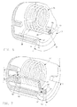
- the embodiment of the invention shown in Figures 7, 8 and 9, utilizes a throttle body housing 12' having first and second housing stops 50,52 located in arcuately separated positions about the throttle valve shaft axis.
- the ends 38',40' of the spring member 36' separately engage the housing stops 50,52, respectively.
- the first spring end 38' engages first housing stop 50 and exerts a force Fa in the counterclockwise direction, as viewed in the Figures, while the second spring end 40' engages second housing stop 52 and exerts a force Fb in the clockwise direction.
- the default position of the throttle valve is defined across an arc between the stops 50,52 and the spring actuation tang 48' depending from the throttle valve shaft will similarly include the arc between its actuating faces 54,56.
- tang 48' is illustrated as a one piece body in the Figures, it is contemplated that multiple tangs having faces 54,56 rotating in a fixed relationship to each other are equally suitable to the present application.
- the actuator will rotate the throttle valve through a range of motion extending between the minimum air flow position "A” and the maximum air flow position "B”; the range of motion including the default position "C".
- the first spring end 38' is moved off of its seated position against the housing stop 50.
- force Fa is exerted on the spring actuating tang 48' and acts to return the tang to the default position "C”.
- the disclosed invention provides an air control valve for an internal combustion engine in which the throttle valve is positioned through an electronic actuator.
- a default position providing positive air flow to the engine is achieved through the use of a single spring.
- the throttle default position lies between the minimum and maximum air flow positions of the throttle valve.
Claims (1)
- Luftsteuerungsventil (10) zum Dosieren von Verbrennungsluft in einen Verbrennungsmotor, umfassend ein Drosselgehäuse (12) durch das hindurch sich ein Luftdurchgang (14) erstreckt, ein Drosselventil (16), das zur Drehung in dem Luftdurchgang angebracht ist, um die Strömung von Luft durch diesen hindurch zu verändern, wobei das Ventil eine Drosselklappe (18) umfaßt, die an einer Welle (20) angebracht ist, die um eine Achse (24) herum drehbar ist, wobei das Ventil innerhalb eines Bereiches zwischen einer ersten Stellung einer minimalen Luftströmung (A) und einer zweiten Stellung einer maximalen Luftströmung (B) positionierbar ist, wobei der Bereich eine Vorgabestellung (C) zwischen der minimalen und der maximalen Stellung umfaßt, eine spiralförmig gewickelte Torsionsfeder (36), die in einer koaxialen Beziehung zur Drosselventilwelle angeordnet ist, wobei die Feder ein erstes Ende (38') aufweist, das angrenzend an eine erste Anschlagfläche (44) angeordnet ist und auf diese eine erste Kraft in einer ersten Richtung ausübt, und ein zweites Ende (40') aufweist, das angrenzend an eine zweite Anschlagfläche (46) angeordnet ist und auf diese eine zweite Kraft ausübt, die der Kraft von dem ersten Federende entgegenwirkt, wobei die Drosselventilwelle ein Federstellglied (48') aufweist, das von dieser absteht und mit dieser drehbar ist, wobei das Stellglied zwischen der ersten und der zweiten Anschlagfläche positioniert ist, um die Welle und das Drosselventil in der Stellung der Vorgabeluftströmung anzuordnen, und dazu dient, das erste Federende von der ersten Anschlagfläche weg gegen die erste Kraft zu bewegen, wenn sich das Drosselventil zwischen der Stellung der minimalen Luftströmung und der Stellung der Vorgabeluftströmung bewegt, und dazu dient, das zweite Federende von der zweiten Anschlagfläche weg gegen die zweite entgegenwirkende Kraft zu bewegen, wenn sich das Drosselventil zwischen der Stellung der Vorgabeluftströmung und der Stellung der maximalen Luftströmung bewegt, wobei die erste und die zweite Kraft dazu dienen, das Drosselklappenfederstellglied zu dem Ort zwischen der ersten und der zweiten Anschlagfläche zurückzuführen, um dadurch das Drosselventil über den ganzen Drosselventilbereich hinweg in die Stellung der Vorgabeluftströmung zurückzuführen.
Applications Claiming Priority (2)
| Application Number | Priority Date | Filing Date | Title |
|---|---|---|---|
| US08/316,418 US5492097A (en) | 1994-09-30 | 1994-09-30 | Throttle body default actuation |
| US316418 | 1999-05-21 |
Publications (2)
| Publication Number | Publication Date |
|---|---|
| EP0704609A1 EP0704609A1 (de) | 1996-04-03 |
| EP0704609B1 true EP0704609B1 (de) | 1999-12-15 |
Family
ID=23228972
Family Applications (1)
| Application Number | Title | Priority Date | Filing Date |
|---|---|---|---|
| EP95202381A Revoked EP0704609B1 (de) | 1994-09-30 | 1995-09-04 | Orosselklappengehäuse Fehlerbetätigung |
Country Status (3)
| Country | Link |
|---|---|
| US (1) | US5492097A (de) |
| EP (1) | EP0704609B1 (de) |
| DE (1) | DE69513921T2 (de) |
Families Citing this family (47)
| Publication number | Priority date | Publication date | Assignee | Title |
|---|---|---|---|---|
| JP3166546B2 (ja) * | 1994-08-17 | 2001-05-14 | トヨタ自動車株式会社 | 内燃機関 |
| DE19612869A1 (de) * | 1996-03-30 | 1997-10-02 | Bosch Gmbh Robert | Steuereinrichtung zum Steuern einer Leistung einer Antriebsmaschine |
| EP1512857A3 (de) * | 1996-09-03 | 2011-04-20 | Hitachi Automotive Systems, Ltd. | Drosselklappen-Betätigungsvorrichtung für eine Brennkraftmaschine |
| JPH10153142A (ja) * | 1996-11-21 | 1998-06-09 | Aisin Seiki Co Ltd | スロットル制御装置 |
| JP3877835B2 (ja) * | 1997-05-19 | 2007-02-07 | 三菱電機株式会社 | 自動車のスロットル制御装置 |
| DE19735046A1 (de) * | 1997-08-13 | 1999-04-22 | Pierburg Ag | Anordnung einer Klammerfeder |
| DE19736521A1 (de) * | 1997-08-22 | 1999-02-25 | Mannesmann Vdo Ag | Lastverstellvorrichtung |
| US5992378A (en) * | 1998-03-25 | 1999-11-30 | Ford Motor Company | Self-aligning throttle plate |
| US6006722A (en) * | 1998-06-12 | 1999-12-28 | General Motors Corporation | Fine resolution air control valve |
| FR2781525B1 (fr) * | 1998-07-22 | 2000-09-22 | Coutier Moulage Gen Ind | Boitier papillon motorise comportant un dispositif de securite dit "limp home" |
| US6070852A (en) * | 1999-01-29 | 2000-06-06 | Ford Motor Company | Electronic throttle control system |
| US6095488A (en) * | 1999-01-29 | 2000-08-01 | Ford Global Technologies, Inc. | Electronic throttle control with adjustable default mechanism |
| US6155533C1 (en) * | 1999-01-29 | 2002-07-30 | Visteon Global Tech Inc | Default mechanism for electronic throttle control system |
| US6244565B1 (en) | 1999-01-29 | 2001-06-12 | Ford Global Technologies, Inc. | Throttle body shaft axial play control |
| US6299545B1 (en) | 1999-05-03 | 2001-10-09 | Visteon Global Tech., Inc. | Rotating shaft assembly |
| US6375151B1 (en) | 1999-09-08 | 2002-04-23 | Siemens Canada Limited | Return spring mechanism for an electronic throttle control assembly |
| US6173939B1 (en) | 1999-11-10 | 2001-01-16 | Ford Global Technologies, Inc. | Electronic throttle control system with two-spring failsafe mechanism |
| US6286481B1 (en) * | 1999-11-11 | 2001-09-11 | Ford Global Technologies, Inc. | Electronic throttle return mechanism with a two-spring and one lever default mechanism |
| US6267352B1 (en) * | 1999-11-11 | 2001-07-31 | Ford Global Technologies, Inc. | Electronic throttle return mechanism with default and gear backlash control |
| DE10013917A1 (de) * | 2000-03-21 | 2001-09-27 | Bosch Gmbh Robert | Vorrichtung zur Rückstellung einer Drosselklappe |
| FR2808563B1 (fr) * | 2000-05-05 | 2002-07-19 | Sagem | Dispositif de commande de la rotation d'un papillon motorise et asservi pour le controle du debit d'un melange comburant alimentant un moteur a combustion interne |
| US6431340B1 (en) * | 2000-11-07 | 2002-08-13 | Siemens Vdo Automotive Corporation | Soft stop mechanism and method |
| US6522038B2 (en) | 2000-12-15 | 2003-02-18 | Delphi Technologies, Inc. | Integrated air control valve using contactless technology |
| JP3945568B2 (ja) | 2000-12-27 | 2007-07-18 | 株式会社デンソー | 内燃機関の吸気制御装置 |
| DE10102775A1 (de) * | 2001-01-23 | 2002-07-25 | Bosch Gmbh Robert | Vorrichtung zur Rückstellung eines Drehglieds |
| DE10102776A1 (de) | 2001-01-23 | 2002-07-25 | Bosch Gmbh Robert | Vorrichtung zur Rückstellung eines Drehglieds |
| JP3863008B2 (ja) * | 2001-11-20 | 2006-12-27 | 本田技研工業株式会社 | 内燃機関の出力制御装置 |
| DE10202096A1 (de) * | 2002-01-21 | 2003-07-24 | Siemens Ag | Drosselklappenstutzen |
| JP3750934B2 (ja) | 2002-02-25 | 2006-03-01 | 三菱電機株式会社 | 吸気絞弁装置 |
| JP3872743B2 (ja) * | 2002-03-28 | 2007-01-24 | 株式会社日立製作所 | スロットルバルブ開閉装置 |
| US6683429B2 (en) * | 2002-04-24 | 2004-01-27 | Borgwarner Inc. | Electric positional actuator |
| JP2004150324A (ja) * | 2002-10-30 | 2004-05-27 | Denso Corp | 電子制御式スロットル制御装置 |
| DE602004006038T2 (de) * | 2003-03-07 | 2008-01-10 | Denso Corp., Kariya | Elektronische Drosselklappensteuereinrichtung |
| JP2006022660A (ja) * | 2004-07-06 | 2006-01-26 | Denso Corp | 内燃機関用吸気制御装置 |
| JP4353291B2 (ja) * | 2007-09-20 | 2009-10-28 | 株式会社デンソー | バルブ開閉制御装置 |
| DE102009020245A1 (de) * | 2009-05-07 | 2011-09-15 | Pierburg Gmbh | Planetengetriebevorrichtung für eine Regelvorrichtung einer Verbrennungskraftmaschine |
| EP2412960A1 (de) | 2010-07-30 | 2012-02-01 | Perkins Engines Company Limited | Abgasrückführungsvorrichtung |
| US9127854B2 (en) * | 2012-04-12 | 2015-09-08 | Airfixture Llc | Damper vane and housing construction |
| JP2017067067A (ja) * | 2015-09-30 | 2017-04-06 | 株式会社デンソー | 捩りばね |
| JP6354724B2 (ja) * | 2015-10-02 | 2018-07-11 | 株式会社デンソー | 吸気制御装置 |
| US10138820B2 (en) | 2015-11-25 | 2018-11-27 | Continental Automotive Systems, Inc. | Electronic throttle control assembly with default airflow adjustment pin |
| JP6675959B2 (ja) * | 2016-09-07 | 2020-04-08 | 愛三工業株式会社 | スロットル装置及びその製造方法 |
| US10138821B1 (en) | 2017-08-31 | 2018-11-27 | GM Global Technology Operations LLC | Method of making a throttle body |
| US10151251B1 (en) | 2017-11-14 | 2018-12-11 | GM Global Technology Operations LLC | Method and controller for engine torque control in a vehicle during a default throttle condition |
| JP6963519B2 (ja) | 2018-02-02 | 2021-11-10 | 株式会社ミクニ | スロットル装置 |
| CA3125906C (en) * | 2019-01-15 | 2024-01-02 | Shanghai Auzone Auto Parts Manufacturing Co., Ltd | Reset mechanism for electronic throttle body |
| DE102019104018A1 (de) * | 2019-02-18 | 2020-08-20 | Friedrich Boysen Gmbh & Co. Kg | Klappeneinrichtung |
Family Cites Families (8)
| Publication number | Priority date | Publication date | Assignee | Title |
|---|---|---|---|---|
| US4867122A (en) * | 1988-09-12 | 1989-09-19 | Sumitomo Electric Industries, Ltd. | Throttle opening control actuator |
| DE58907650D1 (de) * | 1989-03-25 | 1994-06-16 | Audi Ag | Drosselklappe. |
| JP3205002B2 (ja) * | 1991-05-20 | 2001-09-04 | 株式会社日立製作所 | スロットルアクチュエータ |
| DE4243893C2 (de) * | 1991-12-26 | 1996-03-28 | Hitachi Ltd | Vorrichtung zum Steuern einer Drosselklappe einer Brennkraftmaschine |
| US5301646A (en) * | 1991-12-27 | 1994-04-12 | Aisin Seiki Kabushiki Kaisha | Throttle control apparatus |
| DE4337184A1 (de) * | 1993-10-30 | 1995-05-04 | Pierburg Gmbh | Drosselklappenstutzen |
| US5429090A (en) * | 1994-02-28 | 1995-07-04 | Coltec Industries Inc. | Fail safe throttle positioning system |
| DE9409891U1 (de) * | 1994-06-18 | 1994-08-11 | A B Elektronik Gmbh | Anordnung zur Notfahrstellung eines Drosselklappenelements |
-
1994
- 1994-09-30 US US08/316,418 patent/US5492097A/en not_active Expired - Lifetime
-
1995
- 1995-09-04 EP EP95202381A patent/EP0704609B1/de not_active Revoked
- 1995-09-04 DE DE69513921T patent/DE69513921T2/de not_active Revoked
Also Published As
| Publication number | Publication date |
|---|---|
| DE69513921D1 (de) | 2000-01-20 |
| US5492097A (en) | 1996-02-20 |
| DE69513921T2 (de) | 2000-04-20 |
| EP0704609A1 (de) | 1996-04-03 |
Similar Documents
| Publication | Publication Date | Title |
|---|---|---|
| EP0704609B1 (de) | Orosselklappengehäuse Fehlerbetätigung | |
| EP1170487B1 (de) | Elektronisches Drosselklappensteuersystem mit reduzierter Reibung und reduziertem Verschleiss | |
| EP1170484B1 (de) | Elektronische Drosselklappensteuervorrichtung mit Aufrechterhaltung von Zahnradkamm und Zahnradausrichtung | |
| USRE40350E1 (en) | Fail safe throttle positioning system | |
| US4840350A (en) | Electrically actuated EGR valve | |
| US5983858A (en) | Throttle device for internal combustion engine | |
| EP1219803B1 (de) | Sicherheitsluftansaugsteuervorrichtung | |
| US4060063A (en) | Throttle positioner | |
| EP1357453B1 (de) | Elektrischer Stellantrieb | |
| US6843239B2 (en) | High speed exhaust gas recirculation valve | |
| US5423299A (en) | Control valve opening control apparatus | |
| US4438745A (en) | Engine idle speed control device | |
| EP0574093A1 (de) | Ventilzusammenbau | |
| US5829409A (en) | Throttle valve control apparatus | |
| US5762044A (en) | Throttle valve return mechanism for engine throttle valve | |
| EP1170486A2 (de) | Integriertes modulares elektronisches Drosselklappensteuersystem | |
| US6561161B2 (en) | Throttle valve configuration having an emergency air device | |
| JP3397613B2 (ja) | 往復動機構の位置戻し或いは保持装置 | |
| US6622984B2 (en) | Electronic throttle body with low friction default mechanism | |
| US4870990A (en) | Double-flow butterfly valve part | |
| JPH04219426A (ja) | 調節部材を有する装置 | |
| US6868828B2 (en) | Idle speed control apparatus in throttle body | |
| US5065722A (en) | Apparatus having a control motor for intervention into a force transmission device | |
| EP0262883A1 (de) | Drosselvorrichtung für ein Fahrzeug | |
| US6085722A (en) | Exhaust restrictor with gear motor actuator and method of controlling same |
Legal Events
| Date | Code | Title | Description |
|---|---|---|---|
| PUAI | Public reference made under article 153(3) epc to a published international application that has entered the european phase |
Free format text: ORIGINAL CODE: 0009012 |
|
| AK | Designated contracting states |
Kind code of ref document: A1 Designated state(s): DE FR GB |
|
| 17P | Request for examination filed |
Effective date: 19961004 |
|
| 17Q | First examination report despatched |
Effective date: 19980819 |
|
| GRAG | Despatch of communication of intention to grant |
Free format text: ORIGINAL CODE: EPIDOS AGRA |
|
| GRAG | Despatch of communication of intention to grant |
Free format text: ORIGINAL CODE: EPIDOS AGRA |
|
| GRAH | Despatch of communication of intention to grant a patent |
Free format text: ORIGINAL CODE: EPIDOS IGRA |
|
| GRAH | Despatch of communication of intention to grant a patent |
Free format text: ORIGINAL CODE: EPIDOS IGRA |
|
| GRAA | (expected) grant |
Free format text: ORIGINAL CODE: 0009210 |
|
| AK | Designated contracting states |
Kind code of ref document: B1 Designated state(s): DE FR GB |
|
| REF | Corresponds to: |
Ref document number: 69513921 Country of ref document: DE Date of ref document: 20000120 |
|
| ET | Fr: translation filed | ||
| PLBI | Opposition filed |
Free format text: ORIGINAL CODE: 0009260 |
|
| PLBI | Opposition filed |
Free format text: ORIGINAL CODE: 0009260 |
|
| PGFP | Annual fee paid to national office [announced via postgrant information from national office to epo] |
Ref country code: GB Payment date: 20000904 Year of fee payment: 6 |
|
| PGFP | Annual fee paid to national office [announced via postgrant information from national office to epo] |
Ref country code: FR Payment date: 20000915 Year of fee payment: 6 |
|
| 26 | Opposition filed |
Opponent name: ROBERT BOSCH GMBH Effective date: 20000805 |
|
| 26 | Opposition filed |
Opponent name: PIERBURG AG Effective date: 20000816 Opponent name: ROBERT BOSCH GMBH Effective date: 20000805 |
|
| PLBF | Reply of patent proprietor to notice(s) of opposition |
Free format text: ORIGINAL CODE: EPIDOS OBSO |
|
| PGFP | Annual fee paid to national office [announced via postgrant information from national office to epo] |
Ref country code: DE Payment date: 20001026 Year of fee payment: 6 |
|
| PLBF | Reply of patent proprietor to notice(s) of opposition |
Free format text: ORIGINAL CODE: EPIDOS OBSO |
|
| RDAH | Patent revoked |
Free format text: ORIGINAL CODE: EPIDOS REVO |
|
| RDAG | Patent revoked |
Free format text: ORIGINAL CODE: 0009271 |
|
| STAA | Information on the status of an ep patent application or granted ep patent |
Free format text: STATUS: PATENT REVOKED |
|
| 27W | Patent revoked |
Effective date: 20010209 |
|
| GBPR | Gb: patent revoked under art. 102 of the ep convention designating the uk as contracting state |
Free format text: 20010209 |