EP0703412A2 - Procédé de réduction des émissions gazeuses de composés halogénés dans un réacteur à lit fluidisé - Google Patents
Procédé de réduction des émissions gazeuses de composés halogénés dans un réacteur à lit fluidisé Download PDFInfo
- Publication number
- EP0703412A2 EP0703412A2 EP95306559A EP95306559A EP0703412A2 EP 0703412 A2 EP0703412 A2 EP 0703412A2 EP 95306559 A EP95306559 A EP 95306559A EP 95306559 A EP95306559 A EP 95306559A EP 0703412 A2 EP0703412 A2 EP 0703412A2
- Authority
- EP
- European Patent Office
- Prior art keywords
- flue gases
- baghouse
- particles
- halogen
- reactor
- Prior art date
- Legal status (The legal status is an assumption and is not a legal conclusion. Google has not performed a legal analysis and makes no representation as to the accuracy of the status listed.)
- Granted
Links
- 238000000034 method Methods 0.000 title claims abstract description 27
- 150000002366 halogen compounds Chemical class 0.000 title claims abstract description 16
- 239000003546 flue gas Substances 0.000 claims abstract description 38
- 229910052736 halogen Inorganic materials 0.000 claims abstract description 25
- 150000002367 halogens Chemical class 0.000 claims abstract description 25
- 239000002245 particle Substances 0.000 claims abstract description 21
- 239000007789 gas Substances 0.000 claims abstract description 16
- 238000002485 combustion reaction Methods 0.000 claims description 19
- 239000002594 sorbent Substances 0.000 claims description 13
- 239000000446 fuel Substances 0.000 claims description 12
- 238000010521 absorption reaction Methods 0.000 claims description 7
- 239000007787 solid Substances 0.000 claims description 7
- 239000000463 material Substances 0.000 claims description 6
- 230000001105 regulatory effect Effects 0.000 claims description 5
- 238000012544 monitoring process Methods 0.000 claims description 4
- XTQHKBHJIVJGKJ-UHFFFAOYSA-N sulfur monoxide Chemical class S=O XTQHKBHJIVJGKJ-UHFFFAOYSA-N 0.000 claims description 4
- 229910052815 sulfur oxide Inorganic materials 0.000 claims description 4
- 230000001276 controlling effect Effects 0.000 claims 4
- 238000004064 recycling Methods 0.000 claims 1
- 239000010419 fine particle Substances 0.000 abstract description 16
- 235000019738 Limestone Nutrition 0.000 description 20
- 239000006028 limestone Substances 0.000 description 20
- 239000000203 mixture Substances 0.000 description 14
- 239000003245 coal Substances 0.000 description 9
- 235000008733 Citrus aurantifolia Nutrition 0.000 description 7
- 235000011941 Tilia x europaea Nutrition 0.000 description 7
- 239000004571 lime Substances 0.000 description 7
- 238000012806 monitoring device Methods 0.000 description 7
- XLYOFNOQVPJJNP-UHFFFAOYSA-N water Substances O XLYOFNOQVPJJNP-UHFFFAOYSA-N 0.000 description 7
- 238000011084 recovery Methods 0.000 description 5
- 239000011236 particulate material Substances 0.000 description 4
- 238000012546 transfer Methods 0.000 description 4
- 238000006243 chemical reaction Methods 0.000 description 3
- 238000002347 injection Methods 0.000 description 3
- 239000007924 injection Substances 0.000 description 3
- 238000001694 spray drying Methods 0.000 description 3
- 238000005200 wet scrubbing Methods 0.000 description 3
- 239000007864 aqueous solution Substances 0.000 description 2
- 150000001875 compounds Chemical class 0.000 description 2
- 238000010276 construction Methods 0.000 description 2
- 230000003993 interaction Effects 0.000 description 2
- 230000000717 retained effect Effects 0.000 description 2
- ZAMOUSCENKQFHK-UHFFFAOYSA-N Chlorine atom Chemical compound [Cl] ZAMOUSCENKQFHK-UHFFFAOYSA-N 0.000 description 1
- PXGOKWXKJXAPGV-UHFFFAOYSA-N Fluorine Chemical compound FF PXGOKWXKJXAPGV-UHFFFAOYSA-N 0.000 description 1
- 239000012670 alkaline solution Substances 0.000 description 1
- 230000003190 augmentative effect Effects 0.000 description 1
- 238000005452 bending Methods 0.000 description 1
- 229910052801 chlorine Inorganic materials 0.000 description 1
- 239000000460 chlorine Substances 0.000 description 1
- 239000010883 coal ash Substances 0.000 description 1
- 239000011362 coarse particle Substances 0.000 description 1
- 238000004891 communication Methods 0.000 description 1
- 239000002826 coolant Substances 0.000 description 1
- 238000005260 corrosion Methods 0.000 description 1
- 230000007797 corrosion Effects 0.000 description 1
- 238000013461 design Methods 0.000 description 1
- 238000007599 discharging Methods 0.000 description 1
- TXKMVPPZCYKFAC-UHFFFAOYSA-N disulfur monoxide Inorganic materials O=S=S TXKMVPPZCYKFAC-UHFFFAOYSA-N 0.000 description 1
- 239000010459 dolomite Substances 0.000 description 1
- 229910000514 dolomite Inorganic materials 0.000 description 1
- 238000005203 dry scrubbing Methods 0.000 description 1
- 230000000694 effects Effects 0.000 description 1
- 230000007613 environmental effect Effects 0.000 description 1
- 239000004744 fabric Substances 0.000 description 1
- 239000012530 fluid Substances 0.000 description 1
- 229910052731 fluorine Inorganic materials 0.000 description 1
- 239000011737 fluorine Substances 0.000 description 1
- 239000012433 hydrogen halide Substances 0.000 description 1
- 229910000039 hydrogen halide Inorganic materials 0.000 description 1
- -1 lime Chemical class 0.000 description 1
- 239000008239 natural water Substances 0.000 description 1
- 238000005201 scrubbing Methods 0.000 description 1
- 239000000126 substance Substances 0.000 description 1
- 238000011144 upstream manufacturing Methods 0.000 description 1
- 239000002699 waste material Substances 0.000 description 1
Images
Classifications
-
- F—MECHANICAL ENGINEERING; LIGHTING; HEATING; WEAPONS; BLASTING
- F23—COMBUSTION APPARATUS; COMBUSTION PROCESSES
- F23C—METHODS OR APPARATUS FOR COMBUSTION USING FLUID FUEL OR SOLID FUEL SUSPENDED IN A CARRIER GAS OR AIR
- F23C10/00—Fluidised bed combustion apparatus
- F23C10/02—Fluidised bed combustion apparatus with means specially adapted for achieving or promoting a circulating movement of particles within the bed or for a recirculation of particles entrained from the bed
- F23C10/04—Fluidised bed combustion apparatus with means specially adapted for achieving or promoting a circulating movement of particles within the bed or for a recirculation of particles entrained from the bed the particles being circulated to a section, e.g. a heat-exchange section or a return duct, at least partially shielded from the combustion zone, before being reintroduced into the combustion zone
- F23C10/08—Fluidised bed combustion apparatus with means specially adapted for achieving or promoting a circulating movement of particles within the bed or for a recirculation of particles entrained from the bed the particles being circulated to a section, e.g. a heat-exchange section or a return duct, at least partially shielded from the combustion zone, before being reintroduced into the combustion zone characterised by the arrangement of separation apparatus, e.g. cyclones, for separating particles from the flue gases
- F23C10/10—Fluidised bed combustion apparatus with means specially adapted for achieving or promoting a circulating movement of particles within the bed or for a recirculation of particles entrained from the bed the particles being circulated to a section, e.g. a heat-exchange section or a return duct, at least partially shielded from the combustion zone, before being reintroduced into the combustion zone characterised by the arrangement of separation apparatus, e.g. cyclones, for separating particles from the flue gases the separation apparatus being located outside the combustion chamber
-
- F—MECHANICAL ENGINEERING; LIGHTING; HEATING; WEAPONS; BLASTING
- F23—COMBUSTION APPARATUS; COMBUSTION PROCESSES
- F23J—REMOVAL OR TREATMENT OF COMBUSTION PRODUCTS OR COMBUSTION RESIDUES; FLUES
- F23J15/00—Arrangements of devices for treating smoke or fumes
- F23J15/02—Arrangements of devices for treating smoke or fumes of purifiers, e.g. for removing noxious material
- F23J15/022—Arrangements of devices for treating smoke or fumes of purifiers, e.g. for removing noxious material for removing solid particulate material from the gasflow
- F23J15/025—Arrangements of devices for treating smoke or fumes of purifiers, e.g. for removing noxious material for removing solid particulate material from the gasflow using filters
-
- F—MECHANICAL ENGINEERING; LIGHTING; HEATING; WEAPONS; BLASTING
- F23—COMBUSTION APPARATUS; COMBUSTION PROCESSES
- F23J—REMOVAL OR TREATMENT OF COMBUSTION PRODUCTS OR COMBUSTION RESIDUES; FLUES
- F23J2215/00—Preventing emissions
- F23J2215/30—Halogen; Compounds thereof
-
- F—MECHANICAL ENGINEERING; LIGHTING; HEATING; WEAPONS; BLASTING
- F23—COMBUSTION APPARATUS; COMBUSTION PROCESSES
- F23J—REMOVAL OR TREATMENT OF COMBUSTION PRODUCTS OR COMBUSTION RESIDUES; FLUES
- F23J2217/00—Intercepting solids
- F23J2217/10—Intercepting solids by filters
- F23J2217/101—Baghouse type
-
- F—MECHANICAL ENGINEERING; LIGHTING; HEATING; WEAPONS; BLASTING
- F23—COMBUSTION APPARATUS; COMBUSTION PROCESSES
- F23J—REMOVAL OR TREATMENT OF COMBUSTION PRODUCTS OR COMBUSTION RESIDUES; FLUES
- F23J2219/00—Treatment devices
- F23J2219/60—Sorption with dry devices, e.g. beds
-
- Y—GENERAL TAGGING OF NEW TECHNOLOGICAL DEVELOPMENTS; GENERAL TAGGING OF CROSS-SECTIONAL TECHNOLOGIES SPANNING OVER SEVERAL SECTIONS OF THE IPC; TECHNICAL SUBJECTS COVERED BY FORMER USPC CROSS-REFERENCE ART COLLECTIONS [XRACs] AND DIGESTS
- Y10—TECHNICAL SUBJECTS COVERED BY FORMER USPC
- Y10S—TECHNICAL SUBJECTS COVERED BY FORMER USPC CROSS-REFERENCE ART COLLECTIONS [XRACs] AND DIGESTS
- Y10S423/00—Chemistry of inorganic compounds
- Y10S423/05—Automatic, including computer, control
-
- Y—GENERAL TAGGING OF NEW TECHNOLOGICAL DEVELOPMENTS; GENERAL TAGGING OF CROSS-SECTIONAL TECHNOLOGIES SPANNING OVER SEVERAL SECTIONS OF THE IPC; TECHNICAL SUBJECTS COVERED BY FORMER USPC CROSS-REFERENCE ART COLLECTIONS [XRACs] AND DIGESTS
- Y10—TECHNICAL SUBJECTS COVERED BY FORMER USPC
- Y10S—TECHNICAL SUBJECTS COVERED BY FORMER USPC CROSS-REFERENCE ART COLLECTIONS [XRACs] AND DIGESTS
- Y10S423/00—Chemistry of inorganic compounds
- Y10S423/06—Temperature control
-
- Y—GENERAL TAGGING OF NEW TECHNOLOGICAL DEVELOPMENTS; GENERAL TAGGING OF CROSS-SECTIONAL TECHNOLOGIES SPANNING OVER SEVERAL SECTIONS OF THE IPC; TECHNICAL SUBJECTS COVERED BY FORMER USPC CROSS-REFERENCE ART COLLECTIONS [XRACs] AND DIGESTS
- Y10—TECHNICAL SUBJECTS COVERED BY FORMER USPC
- Y10S—TECHNICAL SUBJECTS COVERED BY FORMER USPC CROSS-REFERENCE ART COLLECTIONS [XRACs] AND DIGESTS
- Y10S423/00—Chemistry of inorganic compounds
- Y10S423/09—Reaction techniques
- Y10S423/16—Fluidization
Definitions
- This invention relates to fluidized bed reactors, and more particularly, to a method to reduce the emission of halogen compounds in gaseous products resulting from the combustion of halogen containing fuels in fluidized bed reactors.
- the dry-solids contact process typically involves the injection of a dry, alkaline sorbent-material, such as limestone, into the combustion vessel of a fluidized bed reactor.
- a dry, alkaline sorbent-material such as limestone
- a dry, alkaline, sorbent material such as lime
- the filter thus provides a region in which interaction between the sorbent material and the flue gases can take place.
- the temperature of flue gases containing entrained relatively-fine particles from a fluidized bed reactor is regulated prior to the flue gases entering a baghouse.
- the entrained fine particles, containing significant amounts of unsulfated limestone form a temporary boundary layer on the baghouse filter for the absorption of halogen compounds.
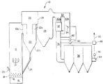
- the steam generator 10 includes a fluidized bed reactor 12 having four walls. It is understood that each wall is formed by a plurality of vertically-disposed tubes interconnected by vertically elongated bars or fins to form a substantially rectangular, contiguous and air-tight structure. Since this type of structure is conventional, it is not shown in the drawings nor will it be described in any further detail.
- a plenum chamber 14 is disposed at the lower portion of the reactor 12 into which pressurized air from a suitable source (not shown) is introduced by conventional means, such as a forced-draft blower, or the like.
- a perforated air distribution plate 16 is suitably supported at the lower end of the combustion chamber of the reactor 12, and above the plenum chamber 14.
- the air introduced through the plenum chamber 14 passes in an upwardly direction through the air distribution plate 16 and may be preheated by air preheaters (not shown) and appropriately regulated by air control dampers as needed.
- the air distribution plate 16 is adapted to support a bed 18 of particulate material consisting in general, of crushed coal, as well as limestone, and/or dolomite, for absorbing a portion of the sulfur oxides (SOx) formed during the combustion of the coal.
- a fuel distributor 20 extends through the front wall of the reactor 12 for introducing particulate fuel into the bed 18, it being understood that other distributors can be associated with the walls of the reactor 12 for distributing particulate sorbent material and/or additional particulate fuel material into the bed 18, as needed.
- a multiplicity of air ports 21 are provided through a side wall of the reactor 12 at a predetermined elevation from the bed 18 to introduce secondary air into the reactor 12 for reasons to be described. It is understood that additional air ports at one or more elevation can be provided through the sidewalls of the reactor 12 as needed.
- the separator 22 includes a hopper portion 22b into which the separated fine particles fall before being passed back into the reactor 12 by a recycle conduit 24.
- a duct 26 is disposed above, and connected to, the cyclone separator 22 and operates to pass the separated flue gases which contain entrained relatively-fine particulate material that was not separated out in the separator 22 to a heat recovery enclosure 28 that is formed adjacent the duct 26.
- An opening 28a is formed in the upper wall portion of the heat recovery enclosure 28 to receive the relatively-clean hot flue gases from the duct 26.
- the heat recovery enclosure 28 is of conventional construction and operates to transfer heat from the hot flue gases to a cooling medium such as water which is in fluid flow relationship with flow conduits, and the like, of the steam generator 10.
- a gas flow duct 30 is formed adjacent the heat recovery enclosure 28 for receiving the relatively-clean flue gases from the enclosure 28 and divides into two branch ducts 30a and 30b.
- An upper economizer 32 is disposed in branch duct 30a and operates to transfer heat from the flue gases to water flowing through conventional water flow circuitry of the economizer.
- a damper 34 is disposed in branch duct 30b and operates to control the flow of flue gases through branch duct 30a for purposes that will be described later.
- a gas flow duct 36 is provided below the branch ducts 30a and 30b for connecting a baghouse 38 in gas flow communication with the ducts 30a and 30b.
- a halogen monitoring device 40 and a temperature monitoring device 42 are connected to the duct 36 and monitor the halogen content and temperature, respectively, of the flue gases entering the baghouse 38.
- the temperature monitoring device 42 is electrically connected to the damper 34 and sends the damper 34 control signals to regulate the flow of the flue gases through the duct 30b and, consequently, the temperature of the flue gases to the baghouse 38.
- the baghouse 38 is of a conventional design and contains, for example, fabric filters in the path of the gases as they pass through the baghouse.
- An outlet duct 44 extends from the baghouse 38 for discharging gases from the baghouse to an external stack, or the like.
- a second halogen monitoring device 46 is connected to the duct 44 for monitoring the halogen content of the flue gases exiting the baghouse 38.
- the halogen monitoring devices 40 and 46 are electrically connected to a control device 48 which operates to produce control signals on a control line shown in part by the reference numeral 50.
- the control line 50 is used to control the baghouse cycle rate and/or the limestone feed rate as necessary to control the emission of halogen compounds.
- a quantity of start-up coal with limestone for absorbing a portion of the sulfur oxides generated as a result of the combustion of the coal is introduced to, and spread over the upper surface of, the particulate material in the bed 18.
- Air is introduced into the plenum chamber 14 and passes through the coal and limestone within the bed 18 and the start-up coal and limestone is ignited by burners (not shown) positioned within the bed.
- burners not shown
- additional air is introduced into the plenum chamber 14 at a relatively high pressure and velocity.
- the bed 18 can be warmed up by a burner located in the plenum chamber 14.
- the primary air introduced through the plenum chamber 14 comprises a fraction of the total air required for complete combustion of the coal so that the combustion in the lower section of the reactor 12 is incomplete.
- the latter section thus operates under reducing conditions and the remaining air required for complete combustion of the coal is supplied by the air ports 21.
- the range of air supplied through the plenum 14 can be from 40% to 90% of that required for complete combustion, with this amount varying according to the desired bed temperature, while the remaining air (60% to 10%) is supplied through the ports 21 to complete the combustion.
- the high-pressure, high-velocity, combustion-supporting air introduced by the air distribution plate 16 from the plenum chamber 14 causes the particles of the relative-fine particulate material, including particles of coal ash and limestone, to become entrained within, and to thus be pneumatically transported by, hot flue gases consisting of air and the gaseous products of combustion.
- This mixture of entrained particles and flue gases rises upwardly within the reactor 12 to form a gas column containing the entrained particles.
- the relatively coarse particles accumulate in the lower portion of the reactor 12 along with a portion of the relatively fine particles while the remaining portion of the relatively fine particles pass upwardly through the gas column.
- the mixture of the hot flue gases and a portion of the relatively fine particles travel the length of the gas column and exit from the reactor 12 through the opening 12a.
- a portion of the relatively fine particles are separated from the hot flue gases within the separator 22 and are recycled back to the fluidized bed 18 through the recycle conduit 24, while the remaining portion of the relatively fine particles remain entrained in the flue gases.
- Particulate fuel material is supplied, in addition to the recycled portion of fine particles, at a sufficient rate to saturate the gas column formed above the bed 18 in the reactor 12, i.e., maximum entrainment of the relatively fine particles by the flue gases is obtained.
- the mixture of hot flue gases and fine particles pass through the heat recovery enclosure 28 in a heat exchange relation with water passing through conventional water flow circuitry (not shown), to transfer heat from the mixture prior to the mixture entering the duct 30 including the branch ducts 30a and 30b.
- the damper 34 receives control signals from the temperature monitoring device 42 and operates to control the temperature of the mixture entering the baghouse 38 by regulating the flow of the mixture through the duct 30b, and therefore through the duct 30a to regulate the transfer of heat from the mixture flowing through the latter duct to the economizer 32.
- the mixture enters the baghouse 38 at a controlled temperature range which preferably is between 525°F and 615°F.
- a portion of the fine particles in the mixture entering the baghouse 38 are particles of limestone which are both unsulfated and have undergone chemical conversion to calcined limestone as a result of the high temperature in the reactor 12.
- the mixture of flue gases and entrained fine particles enter the baghouse 38 and the particles accumulate on the baghouse filter so as to form a temporary layer of sufficient thickness for the flue gases in the mixture to take between 0.1 and 1.0 seconds to traverse the layer.
- the above-mentioned controlled temperature range is conducive to the absorption of halogen compounds in the flue gases by the calcined limestone particles which accumulated on the filter, and the baghouse cycle rate and/or the limestone feed rate are regulated by the control device 48 to maximize the absorption of halogen gases as indicated by the halogen monitoring devices 40 and 46 whose outputs can be used to control the baghouse cycle rate and/or the limestone feed rate, as described above.
- the method of the present invention utilizes the limestone in the entrained fine particles contained in the flue gases for the absorption of halogen compounds resulting from the combustion of fuels containing halogen.
- the use of the limestone particles in this manner results in significant cost savings in that it avoids the recurring costs associated with the procurement of halogen sorbing compounds, such as lime, in addition to the non-recurring cost associated with the equipment required for the injection of halogen sorbing compounds.
- the fluidized bed reactor need not be of the "circulating" type but could be any other type of fluidized bed in which halogen containing fuels undergo combustion in the presence of sulfur-oxide sorbing-materials, such as limestone.
- the absorption of halogen by the limestone can be augmented by injection of other alkaline sorbent material, such as lime, limestone or other halogen sorbing-materials.
Applications Claiming Priority (2)
| Application Number | Priority Date | Filing Date | Title |
|---|---|---|---|
| US312024 | 1994-09-26 | ||
| US08/312,024 US5500195A (en) | 1992-11-13 | 1994-09-26 | Method for reducing gaseous emission of halogen compounds in a fluidized bed reactor |
Publications (3)
| Publication Number | Publication Date |
|---|---|
| EP0703412A2 true EP0703412A2 (fr) | 1996-03-27 |
| EP0703412A3 EP0703412A3 (fr) | 1996-05-15 |
| EP0703412B1 EP0703412B1 (fr) | 1999-11-17 |
Family
ID=23209537
Family Applications (1)
| Application Number | Title | Priority Date | Filing Date |
|---|---|---|---|
| EP95306559A Expired - Lifetime EP0703412B1 (fr) | 1994-09-26 | 1995-09-18 | Procédé de réduction des émissions gazeuses de composés halogénés dans un réacteur à lit fluidisé |
Country Status (7)
| Country | Link |
|---|---|
| US (1) | US5500195A (fr) |
| EP (1) | EP0703412B1 (fr) |
| JP (1) | JP2955835B2 (fr) |
| CA (1) | CA2158804C (fr) |
| DE (1) | DE69513358T2 (fr) |
| ES (1) | ES2139152T3 (fr) |
| FI (1) | FI118460B (fr) |
Cited By (2)
| Publication number | Priority date | Publication date | Assignee | Title |
|---|---|---|---|---|
| US6035628A (en) * | 1997-02-26 | 2000-03-14 | Foster Wheeler Energia Oy | Pressurized fluidized bed combustion system including control of temperature of flue gases entering a high temperature filter |
| WO2016110828A3 (fr) * | 2015-02-13 | 2016-10-13 | Dürr Systems GmbH | Procédé et appareil pour accroître l'efficacité d'une combustion industrielle |
Families Citing this family (26)
| Publication number | Priority date | Publication date | Assignee | Title |
|---|---|---|---|---|
| US5882381A (en) * | 1996-03-28 | 1999-03-16 | Modern Equipment Company, Inc. | Thermal desorption system |
| US6189461B1 (en) * | 1996-12-06 | 2001-02-20 | Nkk Corporation | Burning apparatus and method for restricting the occurrence of dioxins |
| CN1087643C (zh) * | 1997-04-04 | 2002-07-17 | 清华大学 | 干式脱硫剂床料内循环的烟气脱硫方法及装置 |
| US6029956A (en) * | 1998-02-06 | 2000-02-29 | Foster Wheeler Usa Corporation | Predominantly liquid filled vapor-liquid chemical reactor |
| CN1089023C (zh) * | 1998-10-16 | 2002-08-14 | 清华大学 | 中温干式循环流化床烟气脱硫方法及装置 |
| US6352676B1 (en) * | 1999-02-16 | 2002-03-05 | Air Products And Chemicals, Inc. | Abatement of F2 using small particle fluidized bed |
| FR2803369B1 (fr) * | 1999-12-30 | 2002-06-28 | Olivier Francois | Procede de traitement de dechets par combustion |
| CN1113682C (zh) * | 2000-01-05 | 2003-07-09 | 浙江大学 | 高温燃烧两段脱硫方法 |
| CN1114467C (zh) * | 2000-12-15 | 2003-07-16 | 清华大学 | 一种循环悬浮床干法烟气脱硫工艺及其系统 |
| CN1100590C (zh) * | 2000-12-20 | 2003-02-05 | 岳建华 | 高温等离子体烟气脱硫剂 |
| CN1100591C (zh) * | 2000-12-21 | 2003-02-05 | 岳建华 | 高温等离子体烟气脱硫方法 |
| CN100460047C (zh) * | 2006-12-01 | 2009-02-11 | 沙晓农 | 一种循环流化床干法烟气脱硫装置 |
| JP4671976B2 (ja) * | 2007-01-12 | 2011-04-20 | 中国電力株式会社 | 有害微量元素溶出抑制剤添加量算出方法及びこれを用いた有害微量元素溶出抑制方法 |
| JP2008275181A (ja) * | 2007-01-12 | 2008-11-13 | Chugoku Electric Power Co Inc:The | 有害微量元素溶出抑制方法 |
| JP4726813B2 (ja) * | 2007-01-12 | 2011-07-20 | 中国電力株式会社 | 有害微量元素溶出抑制方法 |
| JP4726812B2 (ja) * | 2007-01-12 | 2011-07-20 | 中国電力株式会社 | 有害微量元素溶出抑制方法 |
| JP4726811B2 (ja) * | 2007-01-12 | 2011-07-20 | 中国電力株式会社 | 有害微量元素溶出抑制方法及び石炭火力発電システム |
| US20100206203A1 (en) * | 2007-05-21 | 2010-08-19 | Mario Magaldi | System for dry extracting/cooling heterogeneous material ashes with control of the air inlet in the combustion chamber |
| US8695516B2 (en) * | 2009-04-21 | 2014-04-15 | Industrial Accessories Company | Pollution abatement process for fossil fuel-fired boilers |
| US20100263577A1 (en) * | 2009-04-21 | 2010-10-21 | Industrial Accessories Company | Pollution abatement process for fossil fuel-fired boilers |
| PL2555851T3 (pl) * | 2010-04-07 | 2022-01-10 | Calgon Carbon Corporation | Sposoby usuwania rtęci z gazów spalinowych |
| KR101015154B1 (ko) * | 2010-10-05 | 2011-02-16 | 한국에너지기술연구원 | 황산화물과 붕소화합물을 함유한 고온 배가스용 분말 흡수제 내외부 순환형 산성가스 제거장치 및 이를 이용한 산성가스 제거 방법 |
| US8715402B2 (en) * | 2011-03-22 | 2014-05-06 | Mitsubishi Heavy Industries, Ltd. | Air pollution control system and air pollution control method, spray drying device of dewatering filtration fluid from desulfurization discharged water, and method thereof |
| US20130330257A1 (en) | 2012-06-11 | 2013-12-12 | Calgon Carbon Corporation | Sorbents for removal of mercury |
| US10220369B2 (en) | 2015-08-11 | 2019-03-05 | Calgon Carbon Corporation | Enhanced sorbent formulation for removal of mercury from flue gas |
| CN109092000B (zh) * | 2018-09-26 | 2021-03-23 | 上海交通大学 | 一种多级吸附烟气污染物捕集系统及其净化烟气的方法 |
Citations (1)
| Publication number | Priority date | Publication date | Assignee | Title |
|---|---|---|---|---|
| WO1988010291A1 (fr) | 1987-06-24 | 1988-12-29 | A. Ahlstrom Corporation | Combustion de combustible contenant des acalins |
Family Cites Families (16)
| Publication number | Priority date | Publication date | Assignee | Title |
|---|---|---|---|---|
| DE220905C (fr) * | ||||
| BE560740A (fr) * | 1956-09-12 | 1958-03-11 | ||
| JPS555969B2 (fr) * | 1972-08-22 | 1980-02-12 | ||
| GB1429427A (en) * | 1974-07-25 | 1976-03-24 | Asahi Fibreglass Co | Method of cleaning waste gases containing a fluorine component |
| DE2524540C2 (de) * | 1975-06-03 | 1986-04-24 | Metallgesellschaft Ag, 6000 Frankfurt | Verfahren zur Durchführung endothermer Prozesse |
| SU584882A1 (ru) * | 1976-08-11 | 1977-12-25 | Научно-Исследовательский И Проектный Институт По Комплексной Автоматизации Нефтяной И Химической Промышленности | Способ регулировани процесса абсорбционной очистки газа |
| DE2735436C2 (de) * | 1977-08-05 | 1984-11-29 | Rohrbach, Gerhard, 7461 Dotternhausen | Verfahren zur Entfernung der bei der Verbrennung fossiler Brennstoffe entstandenen Schwefeloxide aus Rauchgasen |
| JPS5437378A (en) * | 1977-08-30 | 1979-03-19 | Ishikawajima Harima Heavy Ind Co Ltd | Removal of hydrogen chloride gas produced in fluidized bed type incinerator |
| DE3235558A1 (de) * | 1982-09-25 | 1984-03-29 | Metallgesellschaft Ag, 6000 Frankfurt | Verfahren zur abtrennung von schadstoffen aus abgasen |
| AT380645B (de) * | 1983-11-25 | 1986-06-25 | Waagner Biro Ag | Verfahren zur abscheidung von sauren schadgasen und verbrennungsanlage zur durchfuehrung des verfahrens |
| JPH0611376B2 (ja) * | 1984-07-25 | 1994-02-16 | バブコツク日立株式会社 | 排ガス中の硫黄化合物およびハロゲン化合物除去方法 |
| US4931264A (en) * | 1986-11-07 | 1990-06-05 | Board Of Regents, The University Of Texas System | Process for removing sulfur from sulfur-containing gases |
| JPH0732862B2 (ja) * | 1989-05-09 | 1995-04-12 | 日立造船株式会社 | 濾過集塵式排ガス処理装置の運転方法 |
| DE3919124A1 (de) * | 1989-06-12 | 1990-01-18 | Haji Javad Mehdi Dr Ing | Verfahren zur abscheidung von polyzylkischen kohlenwasserstoffen und schwermetallen aus abgasen |
| JP2667909B2 (ja) * | 1989-06-23 | 1997-10-27 | 株式会社日立製作所 | エレベータの信号伝送方法 |
| US4981111A (en) * | 1989-11-28 | 1991-01-01 | Air Products And Chemicals, Inc. | Circulating fluidized bed combustion reactor with fly ash recycle |
-
1994
- 1994-09-26 US US08/312,024 patent/US5500195A/en not_active Expired - Lifetime
-
1995
- 1995-09-18 DE DE69513358T patent/DE69513358T2/de not_active Expired - Lifetime
- 1995-09-18 EP EP95306559A patent/EP0703412B1/fr not_active Expired - Lifetime
- 1995-09-18 ES ES95306559T patent/ES2139152T3/es not_active Expired - Lifetime
- 1995-09-18 FI FI954376A patent/FI118460B/fi not_active IP Right Cessation
- 1995-09-21 CA CA002158804A patent/CA2158804C/fr not_active Expired - Fee Related
- 1995-09-22 JP JP7244420A patent/JP2955835B2/ja not_active Expired - Fee Related
Patent Citations (1)
| Publication number | Priority date | Publication date | Assignee | Title |
|---|---|---|---|---|
| WO1988010291A1 (fr) | 1987-06-24 | 1988-12-29 | A. Ahlstrom Corporation | Combustion de combustible contenant des acalins |
Cited By (3)
| Publication number | Priority date | Publication date | Assignee | Title |
|---|---|---|---|---|
| US6035628A (en) * | 1997-02-26 | 2000-03-14 | Foster Wheeler Energia Oy | Pressurized fluidized bed combustion system including control of temperature of flue gases entering a high temperature filter |
| EP0977622B1 (fr) * | 1997-02-26 | 2002-08-28 | Foster Wheeler Energia Oy | Regulation de la temperature a l'entree d'un filtre en ceramique |
| WO2016110828A3 (fr) * | 2015-02-13 | 2016-10-13 | Dürr Systems GmbH | Procédé et appareil pour accroître l'efficacité d'une combustion industrielle |
Also Published As
| Publication number | Publication date |
|---|---|
| DE69513358T2 (de) | 2000-06-08 |
| FI118460B (fi) | 2007-11-30 |
| CA2158804A1 (fr) | 1996-03-27 |
| EP0703412A3 (fr) | 1996-05-15 |
| US5500195A (en) | 1996-03-19 |
| CA2158804C (fr) | 2007-04-24 |
| DE69513358D1 (de) | 1999-12-23 |
| JP2955835B2 (ja) | 1999-10-04 |
| EP0703412B1 (fr) | 1999-11-17 |
| ES2139152T3 (es) | 2000-02-01 |
| FI954376A0 (fi) | 1995-09-18 |
| JPH08178240A (ja) | 1996-07-12 |
| FI954376A (fi) | 1996-03-27 |
Similar Documents
| Publication | Publication Date | Title |
|---|---|---|
| CA2158804C (fr) | Methode pour reduire l'emission gazeuse de composes halogenes dans un reacteur a lit fluidise | |
| US4716856A (en) | Integral fluidized bed heat exchanger in an energy producing plant | |
| US4915061A (en) | Fluidized bed reactor utilizing channel separators | |
| CA2097572A1 (fr) | Systeme de reacteur a lit fluidise et methode faisant appel a un echangeur de chaleur | |
| US5269263A (en) | Fluidized bed reactor system and method of operating same | |
| US4809625A (en) | Method of operating a fluidized bed reactor | |
| US4951612A (en) | Circulating fluidized bed reactor utilizing integral curved arm separators | |
| US5237963A (en) | System and method for two-stage combustion in a fluidized bed reactor | |
| JPH0391603A (ja) | 流動床燃焼方法及び装置 | |
| JPH06134346A (ja) | 流動床反応器用の横型サイクロン分離器 | |
| US5344614A (en) | Reactor for reducing sulfur oxides emissions in a combustion process | |
| EP0698726B1 (fr) | Centrale combinée avec un réacteur sous pression à lit fluidisé circulant | |
| EP0294024A1 (fr) | Procédé d'élimination des oxydes d'azote d'un gaz | |
| US5735682A (en) | Fluidized bed combustion system having an improved loop seal valve | |
| CA1274422A (fr) | Reacteur a lit fluidise, et son exploitation | |
| CN1086300A (zh) | 用于流化床反应器的卧式旋风分离器 | |
| JPH0339808A (ja) | 流動床反応器及びその操作方法 | |
| CN1017826B (zh) | 流化床反应器及其操作方法 |
Legal Events
| Date | Code | Title | Description |
|---|---|---|---|
| PUAI | Public reference made under article 153(3) epc to a published international application that has entered the european phase |
Free format text: ORIGINAL CODE: 0009012 |
|
| AK | Designated contracting states |
Kind code of ref document: A2 Designated state(s): DE ES FR GB IT SE |
|
| PUAL | Search report despatched |
Free format text: ORIGINAL CODE: 0009013 |
|
| AK | Designated contracting states |
Kind code of ref document: A3 Designated state(s): DE ES FR GB IT SE |
|
| 17P | Request for examination filed |
Effective date: 19961025 |
|
| 17Q | First examination report despatched |
Effective date: 19980706 |
|
| GRAG | Despatch of communication of intention to grant |
Free format text: ORIGINAL CODE: EPIDOS AGRA |
|
| GRAG | Despatch of communication of intention to grant |
Free format text: ORIGINAL CODE: EPIDOS AGRA |
|
| GRAG | Despatch of communication of intention to grant |
Free format text: ORIGINAL CODE: EPIDOS AGRA |
|
| GRAG | Despatch of communication of intention to grant |
Free format text: ORIGINAL CODE: EPIDOS AGRA |
|
| GRAH | Despatch of communication of intention to grant a patent |
Free format text: ORIGINAL CODE: EPIDOS IGRA |
|
| GRAH | Despatch of communication of intention to grant a patent |
Free format text: ORIGINAL CODE: EPIDOS IGRA |
|
| GRAA | (expected) grant |
Free format text: ORIGINAL CODE: 0009210 |
|
| AK | Designated contracting states |
Kind code of ref document: B1 Designated state(s): DE ES FR GB IT SE |
|
| REF | Corresponds to: |
Ref document number: 69513358 Country of ref document: DE Date of ref document: 19991223 |
|
| ITF | It: translation for a ep patent filed |
Owner name: ING. C. GREGORJ S.P.A. |
|
| ET | Fr: translation filed | ||
| REG | Reference to a national code |
Ref country code: ES Ref legal event code: FG2A Ref document number: 2139152 Country of ref document: ES Kind code of ref document: T3 |
|
| PLBE | No opposition filed within time limit |
Free format text: ORIGINAL CODE: 0009261 |
|
| STAA | Information on the status of an ep patent application or granted ep patent |
Free format text: STATUS: NO OPPOSITION FILED WITHIN TIME LIMIT |
|
| 26N | No opposition filed | ||
| REG | Reference to a national code |
Ref country code: GB Ref legal event code: IF02 |
|
| PGFP | Annual fee paid to national office [announced via postgrant information from national office to epo] |
Ref country code: GB Payment date: 20120920 Year of fee payment: 18 Ref country code: SE Payment date: 20120919 Year of fee payment: 18 |
|
| PGFP | Annual fee paid to national office [announced via postgrant information from national office to epo] |
Ref country code: DE Payment date: 20120921 Year of fee payment: 18 Ref country code: ES Payment date: 20120919 Year of fee payment: 18 |
|
| PGFP | Annual fee paid to national office [announced via postgrant information from national office to epo] |
Ref country code: FR Payment date: 20121010 Year of fee payment: 18 |
|
| PGFP | Annual fee paid to national office [announced via postgrant information from national office to epo] |
Ref country code: IT Payment date: 20120927 Year of fee payment: 18 |
|
| REG | Reference to a national code |
Ref country code: DE Ref legal event code: R119 Ref document number: 69513358 Country of ref document: DE |
|
| REG | Reference to a national code |
Ref country code: SE Ref legal event code: EUG |
|
| PG25 | Lapsed in a contracting state [announced via postgrant information from national office to epo] |
Ref country code: SE Free format text: LAPSE BECAUSE OF NON-PAYMENT OF DUE FEES Effective date: 20130919 |
|
| GBPC | Gb: european patent ceased through non-payment of renewal fee |
Effective date: 20130918 |
|
| REG | Reference to a national code |
Ref country code: FR Ref legal event code: ST Effective date: 20140530 |
|
| PG25 | Lapsed in a contracting state [announced via postgrant information from national office to epo] |
Ref country code: GB Free format text: LAPSE BECAUSE OF NON-PAYMENT OF DUE FEES Effective date: 20130918 |
|
| PG25 | Lapsed in a contracting state [announced via postgrant information from national office to epo] |
Ref country code: DE Free format text: LAPSE BECAUSE OF NON-PAYMENT OF DUE FEES Effective date: 20140401 Ref country code: FR Free format text: LAPSE BECAUSE OF NON-PAYMENT OF DUE FEES Effective date: 20130930 Ref country code: IT Free format text: LAPSE BECAUSE OF NON-PAYMENT OF DUE FEES Effective date: 20130918 |
|
| REG | Reference to a national code |
Ref country code: ES Ref legal event code: FD2A Effective date: 20141007 |
|
| REG | Reference to a national code |
Ref country code: DE Ref legal event code: R079 Ref document number: 69513358 Country of ref document: DE Free format text: PREVIOUS MAIN CLASS: F23J0015020000 Ipc: B01D0053680000 |
|
| REG | Reference to a national code |
Ref country code: DE Ref legal event code: R119 Ref document number: 69513358 Country of ref document: DE Effective date: 20140401 Ref country code: DE Ref legal event code: R079 Ref document number: 69513358 Country of ref document: DE Free format text: PREVIOUS MAIN CLASS: F23J0015020000 Ipc: B01D0053680000 Effective date: 20141030 |
|
| PG25 | Lapsed in a contracting state [announced via postgrant information from national office to epo] |
Ref country code: ES Free format text: LAPSE BECAUSE OF NON-PAYMENT OF DUE FEES Effective date: 20130919 |