EP0703360B1 - Verfahren und Überwachungseinrichtung zur Fehlererkennung oder zum Warnen eines Fahrzeugführers für einen Fehler der Einlassluftheizvorrichtung - Google Patents
Verfahren und Überwachungseinrichtung zur Fehlererkennung oder zum Warnen eines Fahrzeugführers für einen Fehler der Einlassluftheizvorrichtung Download PDFInfo
- Publication number
- EP0703360B1 EP0703360B1 EP95306692A EP95306692A EP0703360B1 EP 0703360 B1 EP0703360 B1 EP 0703360B1 EP 95306692 A EP95306692 A EP 95306692A EP 95306692 A EP95306692 A EP 95306692A EP 0703360 B1 EP0703360 B1 EP 0703360B1
- Authority
- EP
- European Patent Office
- Prior art keywords
- temperature
- predetermined
- flag
- time period
- engine
- Prior art date
- Legal status (The legal status is an assumption and is not a legal conclusion. Google has not performed a legal analysis and makes no representation as to the accuracy of the status listed.)
- Expired - Lifetime
Links
- 238000010438 heat treatment Methods 0.000 title claims description 71
- 238000000034 method Methods 0.000 title claims description 13
- 230000004044 response Effects 0.000 claims description 9
- 238000002485 combustion reaction Methods 0.000 claims description 8
- 230000003213 activating effect Effects 0.000 claims 11
- 239000003570 air Substances 0.000 description 52
- 238000002405 diagnostic procedure Methods 0.000 description 9
- 238000012360 testing method Methods 0.000 description 7
- 239000000779 smoke Substances 0.000 description 6
- 230000006870 function Effects 0.000 description 4
- 238000004519 manufacturing process Methods 0.000 description 3
- 238000001514 detection method Methods 0.000 description 2
- 238000012774 diagnostic algorithm Methods 0.000 description 2
- 230000000694 effects Effects 0.000 description 2
- 238000005286 illumination Methods 0.000 description 2
- 230000003287 optical effect Effects 0.000 description 2
- 230000000717 retained effect Effects 0.000 description 2
- 239000007858 starting material Substances 0.000 description 2
- 230000000153 supplemental effect Effects 0.000 description 2
- 244000304337 Cuminum cyminum Species 0.000 description 1
- 230000002411 adverse Effects 0.000 description 1
- 230000004075 alteration Effects 0.000 description 1
- 239000012080 ambient air Substances 0.000 description 1
- 230000003750 conditioning effect Effects 0.000 description 1
- 230000001276 controlling effect Effects 0.000 description 1
- 230000001351 cycling effect Effects 0.000 description 1
- 239000000446 fuel Substances 0.000 description 1
- 229930195733 hydrocarbon Natural products 0.000 description 1
- 150000002430 hydrocarbons Chemical class 0.000 description 1
- 239000002085 irritant Substances 0.000 description 1
- 231100000021 irritant Toxicity 0.000 description 1
- 230000007257 malfunction Effects 0.000 description 1
- 238000012986 modification Methods 0.000 description 1
- 230000004048 modification Effects 0.000 description 1
- 238000012806 monitoring device Methods 0.000 description 1
- 238000012545 processing Methods 0.000 description 1
- 230000001737 promoting effect Effects 0.000 description 1
- 230000009467 reduction Effects 0.000 description 1
- 230000001105 regulatory effect Effects 0.000 description 1
- 230000000241 respiratory effect Effects 0.000 description 1
- 230000011664 signaling Effects 0.000 description 1
- 238000012546 transfer Methods 0.000 description 1
- 238000012795 verification Methods 0.000 description 1
- 238000010792 warming Methods 0.000 description 1
Images


Classifications
-
- F—MECHANICAL ENGINEERING; LIGHTING; HEATING; WEAPONS; BLASTING
- F02—COMBUSTION ENGINES; HOT-GAS OR COMBUSTION-PRODUCT ENGINE PLANTS
- F02N—STARTING OF COMBUSTION ENGINES; STARTING AIDS FOR SUCH ENGINES, NOT OTHERWISE PROVIDED FOR
- F02N19/00—Starting aids for combustion engines, not otherwise provided for
- F02N19/02—Aiding engine start by thermal means, e.g. using lighted wicks
- F02N19/04—Aiding engine start by thermal means, e.g. using lighted wicks by heating of fluids used in engines
- F02N19/06—Aiding engine start by thermal means, e.g. using lighted wicks by heating of fluids used in engines by heating of combustion-air by flame generating means, e.g. flame glow-plugs
-
- F—MECHANICAL ENGINEERING; LIGHTING; HEATING; WEAPONS; BLASTING
- F02—COMBUSTION ENGINES; HOT-GAS OR COMBUSTION-PRODUCT ENGINE PLANTS
- F02M—SUPPLYING COMBUSTION ENGINES IN GENERAL WITH COMBUSTIBLE MIXTURES OR CONSTITUENTS THEREOF
- F02M31/00—Apparatus for thermally treating combustion-air, fuel, or fuel-air mixture
- F02M31/02—Apparatus for thermally treating combustion-air, fuel, or fuel-air mixture for heating
- F02M31/04—Apparatus for thermally treating combustion-air, fuel, or fuel-air mixture for heating combustion-air or fuel-air mixture
- F02M31/042—Combustion air
-
- F—MECHANICAL ENGINEERING; LIGHTING; HEATING; WEAPONS; BLASTING
- F02—COMBUSTION ENGINES; HOT-GAS OR COMBUSTION-PRODUCT ENGINE PLANTS
- F02M—SUPPLYING COMBUSTION ENGINES IN GENERAL WITH COMBUSTIBLE MIXTURES OR CONSTITUENTS THEREOF
- F02M31/00—Apparatus for thermally treating combustion-air, fuel, or fuel-air mixture
- F02M31/02—Apparatus for thermally treating combustion-air, fuel, or fuel-air mixture for heating
- F02M31/12—Apparatus for thermally treating combustion-air, fuel, or fuel-air mixture for heating electrically
- F02M31/13—Combustion air
-
- F—MECHANICAL ENGINEERING; LIGHTING; HEATING; WEAPONS; BLASTING
- F02—COMBUSTION ENGINES; HOT-GAS OR COMBUSTION-PRODUCT ENGINE PLANTS
- F02N—STARTING OF COMBUSTION ENGINES; STARTING AIDS FOR SUCH ENGINES, NOT OTHERWISE PROVIDED FOR
- F02N19/00—Starting aids for combustion engines, not otherwise provided for
- F02N19/02—Aiding engine start by thermal means, e.g. using lighted wicks
- F02N19/04—Aiding engine start by thermal means, e.g. using lighted wicks by heating of fluids used in engines
-
- Y—GENERAL TAGGING OF NEW TECHNOLOGICAL DEVELOPMENTS; GENERAL TAGGING OF CROSS-SECTIONAL TECHNOLOGIES SPANNING OVER SEVERAL SECTIONS OF THE IPC; TECHNICAL SUBJECTS COVERED BY FORMER USPC CROSS-REFERENCE ART COLLECTIONS [XRACs] AND DIGESTS
- Y02—TECHNOLOGIES OR APPLICATIONS FOR MITIGATION OR ADAPTATION AGAINST CLIMATE CHANGE
- Y02T—CLIMATE CHANGE MITIGATION TECHNOLOGIES RELATED TO TRANSPORTATION
- Y02T10/00—Road transport of goods or passengers
- Y02T10/10—Internal combustion engine [ICE] based vehicles
- Y02T10/12—Improving ICE efficiencies
Definitions
- This invention relates in general to internal combustion engines and more specifically to air intake heating and diagnostic systems for diesel engines which aid in cold weather starting and control white smoke exhaust emissions upon starting the engine and as required thereafter during operation of the engine.
- white smoke An undesirable phenomenon known as "white smoke” is a frequent side effect of no load or light load diesel engine operation at low temperatures. This phenomenon is essentially the result of unburned hydrocarbons in the engine exhaust and is attributable to misfiring or incomplete combustion in some or all cylinders. White smoke is both a respiratory and optical irritant as well as adversely affecting visibility. While white smoke is not a regulated exhaust emission, sociability of the engine or vehicle suffers as a result of the production of white smoke.
- Trotta et al. discloses a method and apparatus for preheating intake manifold air prior to starting the engine, and for postheating the intake air while the engine is running. In so doing, a pair of intake manifold air heaters are each activated for predetermined durations, and at predetermined duty cycles, according to specific ranges of intake air temperature.
- CARB California Air Resources Board
- OBD II On Board Diagnostics
- the present invention provides a system and method for heating intake manifold air to reduce white smoke while providing continuous diagnostic testing of the various system componentry.
- a system complies with OBD II by continuously warning a driver, under certain conditions more fully described hereinafter, of an existing fault or failure condition within the intake manifold air heating system.
- an air intake heating and diagnostic system for use with a vehicle having an internal combustion engine as claimed in claim 1.
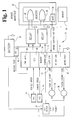
- FIG. 1 is a diagrammatic illustration of an air intake heating and diagnostic system according to one embodiment of the present invention.
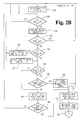
- FIG. 2A is a flowchart of a heater control and system diagnostic software program executed by a microprocessor of the air intake heating and diagnostic system.
- FIG. 2B is a continuation of the flowchart of FIG. 2A.
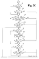
- FIG. 2C is a continuation of the flowchart of FIG. 2B.
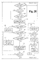
- FIG. 2D is a continuation of the flowchart of FIG. 2C.
- FIG. 2E is a continuation of the flowchart of FIG. 2D.
- FIG. 2F is a continuation of the flowchart of FIG. 2E.
- FIG. 3 is a flowchart of the sensor diagnostics subroutine of FIGS. 2A-2E.
- FIG. 4 is a flowchart of the postheat heater schedule subroutine of FIG. 2E.
- FIG. 5 is a flowchart of the heater diagnostic threshold temperature subroutine of FIG. 2F.
- FIG. 1 a diagrammatic illustration of a microprocessor controlled air intake heating and diagnostic system 10 embodying the present invention is shown.
- the battery 24 provides battery voltage to relays 32 and 34, key switch 22, "wait to start” lamp 36 and “check engine” lamp 38, as well as many other electrical vehicle components, (not shown).
- battery voltage is approximately 12-14 volts, but the system 10 of the present invention must be operable with battery voltages as low as 7 volts and as high as 24 volts.
- Key switch 22 is a three-position switch having an "off” position, an "on” position and a “crank” position. In the “off” position, key switch 22 disconnects battery voltage from the controller 12. In the “on” position, key switch 22 supplies battery voltage to the controller 12.
- key switch 22 In the "crank" position, key switch 22 further supplies battery voltage to an engine starter system (not shown) in order to start the engine.
- the three key positions, or states, described above for key switch 22 correspond to those normally encountered in a motor vehicle wherein the key switch is initially switched from the “off” position to the “run” position to supply power to the electrical system of a vehicle and upon further rotation of the switch to the "crank” position, a starter solenoid of the vehicle is engaged to start the engine.
- the key switch 22 just described is used in a preferred embodiment, the present invention contemplates other switch means for accomplishing the key switch function.
- a "software key", or software controlled system may be used to actuate a system of relays or other switches in order to supply battery voltage to the necessary electrical components.
- Controller 12 is a microcomputer including a microprocessor portion 42, an output driver portion 44 including output interface circuitry, a power supply portion 46, an analog-to-digital convertor portion 48, a memory portion 50 and a supporting circuitry portion 52.
- the microprocessor portion 42 runs software routines and manages the overall operation of the system 10.
- the microprocessor portion 42 may contain the analog-to digital convertor portion 48 for converting analog sensor signals to digital signals for further processing by the microprocessor portion 42.
- microprocessor portion 42 of controller 12 is a Motorolla 68336 microprocessor.
- the memory portion 50 of controller 12 may include ROM, RAM, EPROM, EEPROM, Flash PROM and any other reusable type of memory known to those skilled in the art.
- the memory portion 50 may be further supplemented by memory 40 connected thereto as shown by a dashed-line connection.
- Memory 40 may include any of the memory features described with respect to memory portion 50. Memory 40 may also be used to supplant memory portion 50 if controller 12 lacks a memory portion 50 or if memory portion 50 provides inadequate storage.
- the microprocessor portion 42 may include sufficient memory (including ROM and RAM) to obviate the need for memory portion 50 and/or supplemental memory 40.
- the power supply portion 46 of controller 12 receives electrical power from the battery 24 through key switch 22 when key switch 22 is in the "on" position, and supplies electrical power to the various controller portions as well as supporting circuitry which may be added to the system 10.
- the output driver portion 44 of controller 12 supplies power output signals capable of driving relays, switches and the like.
- the supporting circuitry portion 52 may include, for example, interface circuitry for conditioning input signals, a UART, load dump and electrostatic discharge (ESD) protection circuitry, buffer circuitry and other circuitry commonly associated with microcomputers.
- interface circuitry for conditioning input signals a UART, load dump and electrostatic discharge (ESD) protection circuitry, buffer circuitry and other circuitry commonly associated with microcomputers.
- ESD electrostatic discharge
- Heating elements 26 and 28 are located within the air intake manifold assembly 30. In a preferred embodiment, heating elements 26 and 28 are disposed adjacent to the intake manifold air inlet so that intake air is drawn over elements 26 and 28 before entering the intake manifold 30 during engine operation. Alternatively, heating elements 26 and 28 may be located inside the intake manifold 30 so that intake air is drawn into the engine through the intake manifold 30 and over elements 26 and 28 during operation of the engine. Heating elements 26 and 28, in a preferred embodiment, are rated at 1,050 watts, although the present invention contemplates using heating elements 26 and 28 rated as low as 500 watts and as high as 1,500 watts.
- Relays 32 and 34 connect heaters 26 and 28 to the battery 24, although another source of power, such as the alternator or an auxiliary power supply (not shown), may be used.
- the controller 12 activates or energizes relays 32 and 34, battery voltage is supplied to heaters 26 and 28, respectively.
- FIG. 1 shows two heating elements 26 and 28, the present invention contemplates using a variable number of heating elements depending on the engine model, type and usage. For example, some applications may require only a single heating element while others may call for as many as 8.
- controller 12 In addition to the switched battery voltage supplied to the controller 12 through the key switch 22, signals corresponding to battery temperature, intake manifold air temperature, vehicle speed and engine speed are supplied to inputs of controller 12.
- a battery temperature sensor (BTS) 18 provides the controller 12 with a signal corresponding to battery temperature.
- FIG. 1 shows BTS 18 as being attached to the battery 24, the present invention also contemplates locating BTS 18 within the battery 24 itself.
- An intake manifold air temperature sensor (IMATS) 20 is disposed within the intake manifold of the engine and provides controller 12 with a signal corresponding to the temperature of the air entering the intake manifold.
- An engine speed sensor (ESS) 16 supplies engine speed signals to controller 12 and is used to detect a stalled, cranking and running engine, as well as determined certain engine speed threshold levels discussed hereinafter.
- a stalled or stopped engine is defined as having an engine speed of less than 32 revolutions per minute (RPM).
- RPM revolutions per minute
- a cranking engine is defined as having an engine speed of greater than 32 RPM and less than 480 RPM
- a running engine is defined as having an engine speed above 480 RPM.
- a vehicle speed sensor (VSS) 14 provides controller 12 with a signal corresponding to the speed of the vehicle, and is used to establish an engine load threshold more fully described hereinafter.
- BTS 18, VSS 14, ESS 16 and IMATS 20 are analog sensors known in the automotive art.
- the present invention also contemplates using sensors that supply digital signals corresponding to the sensed parameter in order to accomplish the above-described functions. In so doing, the analog-to-digital convertor portion 48 of controller 12 is no longer necessary and may be omitted.
- the present invention further contemplates using redundant sensors within the system 10 so that the system 10 may remain fully operational while awaiting service on the failed or faulty sensor.
- Controller 12 further supplies signals to operator prompting device 36 and operator warning device 38.
- Operator prompting device 36 is a means for prompting the vehicle operator to wait for a predetermined preheat time period before starting the engine, after switching the key switch from the "off" position to the “on” position.
- Operator warning device 38 is a means for warning the operator of a fault or failure condition within the air intake heating system 10.
- Devices 36 and 38 are connected to the battery 24, or similar power source as described above with respect to the heaters 26 and 28, and are actuated by signals supplied by controller 12.
- the prompting means 36 is the "wait to start" lamp, as shown in FIG.
- the warning means 38 in a preferred embodiment, is the "check engine” lamp, as shown in FIG. 1, which is standard on most vehicles and is located within the instrument panel or cluster (not shown).
- the "check engine” lamp 38 is illuminated by the controller 12 to warn the vehicle operator of a fault condition within the intake air heating system, and continues to warn the operator until the key switch is returned to the "off" position.
- the "wait to start” lamp 36 or the “check engine” lamp 38 may be an incandescent lamp, any number of light emitting diodes (LEDs) or a combination of either type of light source with an optical waveguide.
- the present invention contemplates locating lamps 36 and 38 anywhere on the vehicle that may be observed by the vehicle operator while operating the vehicle.
- either device 36 or 38 may be, or include, an audible device for providing an audible signal, corresponding to the required function, to the vehicle operator.
- the controller 12 energizes or activates heaters 26 and 28 for a variable preheat time period prior to starting the engine in accordance with the initial temperature of the intake manifold air. If "preheat" is successfully completed, the controller 12 cycles heaters 26 and 28 after the engine has been started, for various time periods and duty cycles, for the duration of a postheat time period in accordance with the engine speed and initial temperature of the intake manifold air. Under certain conditions, more fully described hereinafter, the controller 12 continuously runs a heater diagnostic check during postheat to test the operation of heaters 26 and 28. If preheat is not successfully completed, the heater diagnostic check will be aborted.
- the controller 12 continuously executes a sensor diagnostics check from key switch 22 "on” to key switch 22 "off” to test each of the VSS 14, ESS 16, BTS 18 and IMATS 20 for faults and/or failures. Under certain failure or fault conditions, the vehicle operator is warned of the condition and certain sensor fault flags are set within memory portion 50 of controller 12.
- Controller 12 is powered up when key switch 22 is switched from the "off” position to the “on” position. Upon power up, controller 12 resets or initializes its air intake heating and diagnostic algorithm, illuminates the "wait to start” lamp 36, and begins to monitor all sensors for functionality.
- controller 12 If controller 12 senses an initial intake manifold air temperature (IMAT) below a predetermined temperature level for longer than a predetermined time period, controller 12 assumes that IMATS 20 is open-circuited and sets a temporary temperature sensor open-circuit (TSOC) flag within memory portion 50. On the other hand, if controller 12 senses an initial IMAT above another predetermined level for another predetermined time period, controller 12 assumes that IMATS 20 is short-circuited and sets a permanent temperature sensor short-circuit (TSSC) flag within memory portion 50. In a preferred embodiment, controller 12 detects an open-circuited IMATS 20 if the voltage supplied by IMATS 20 to the analog-to-digital portion 48 of controller 12 is below a valid lower threshold voltage level.
- IMAT intake manifold air temperature
- IMATS 20 voltage reading below the valid lower threshold voltage level may not correspond to an actual open-circuited IMATS, it is treated as such by the controller 12 since such an invalid voltage reading is indicative of an IMATS 20 fault condition.
- IMATS 20 voltages readings of below the valid lower threshold voltage level correspond to any temperature reading of below -40 degrees F.
- controller 12 detects a short-circuited IMATS 20 if the voltage supplied by IMATS 20 to the analog-to-digital portion 48 of controller 12 is above a valid upper threshold voltage level.
- an IMATS 20 voltage reading above the valid upper threshold voltage level may not correspond to an actual short-circuited IMATS, it is treated as such by the controller 12 since such an invalid voltage reading is indicative of an IMATS 20 fault condition.
- IMATS 20 voltages readings of above the valid upper threshold voltage level correspond to any temperature reading in excess of 250 degrees F.
- the controller 12 activates the "check engine” lamp 38 until the key switch 22 is returned to the "off” position only if a TSSC condition is detected.
- controller 12 activates the "check engine” lamp 38 until key switch 22 is returned to the "off” position in response to any invalid IMATS 20 voltage reading being detected by controller 12 for longer than 5 seconds,.
- the predetermined time period is set at 5 seconds in a preferred embodiment, the present invention contemplates predetermined time periods of between 0 and 64 seconds.
- the upper and lower predetermined temperature levels of 250 and -40 degrees F are limitations of the IMATS 20 itself and not of the present invention. As such, the present invention contemplates upper and lower predetermined temperature levels corresponding to the limits of the valid sensor voltage vs temperature characteristics of the particular IMATS 20 being used.
- the controller 12 flashes the "wait to start" lamp 36 at approximately 1 Hz until the preheat time period has expired.
- the invention contemplates flashing other lamps in response to the TSOC flag being set, including the "check engine” lamp 38 or other lamp observable by the vehicle operator. Further, the invention contemplates ramping the lamp illumination on and off as well as other flash or ramp rates. An important requirement of this feature is that the flashing or ramping of the lamp must be discernable by the vehicle operator in contrast to the continuous illumination of the lamp.
- Controller 12 further detects open-circuit and short-circuit failure conditions within BTS 18 and sets a battery temperature sensor fault (BTSF) flag within memory portion 50 in response to either.
- BTSF battery temperature sensor fault
- the BTS 18 open-circuit and short-circuit detection is performed identically to the open-circuit and short-circuit detection of IMATS 20 as previously discussed.
- controller 12 sets a vehicle speed sensor fault (VSSF) flag or engine speed sensor fault (ESSF) flag, respectively, within memory portion 50.
- the controller 12 activates the "check engine” lamp 38 if a BTSF, VSSF or ESSF flag is set within the memory portion 50.
- the present invention contemplates alternate embodiments wherein the "check engine” lamp 38 is activated in response to only certain ones of the BTSF, VSSF, ESSF, TSOC and TSSC flags being set, as well as further embodiments wherein only the foregoing flags are set in response to the corresponding fault being detected and the "check engine” lamp 38 is not activated in response thereto.
- the controller 12 determines that the initial IMAT reading is in excess of a preheat threshold temperature, then the controller 12 deactivates the "wait to start" lamp 36 and assumes that no intake manifold air preheating is necessary. In this case, heating elements 26 and 28 are not energized.
- the preheat threshold temperature in a preferred embodiment is 60 degrees F. If the initial IMAT is less than 60 degrees F the controller 12 determines a preheat schedule for energizing heaters 26 and 28 based upon the initial IMAT reading.
- Table 1 provides a suggested guide for determining the preheat schedule although other initial IMAT ranges, heater combinations, preheat durations and duty cycles are contemplated.
- both heaters 26 and 28 are energized continuously for a preheat duration of 30 seconds. If IIMAT is greater than or equal to zero degrees F and less than 16 degrees F, both heaters 26 and 28 are energized continuously for a preheat duration of 15 seconds. Finally, if IIMAT is greater than or equal to 16 degrees F and less than 60 degrees F, both heaters 26 and 28 are energized continuously for a preheat duration of 10 seconds.
- the controller 12 assumes an initial IMAT reading in excess of 60 degrees F and the preheat schedule is aborted. If a TSOC flag was set with the initial IMAT reading, the controller assumes an initial IMAT reading of below zero degrees F and automatically selects the preheat schedule corresponding to IIMAT less than zero degrees F. If a TSOC flag is set at any time during the preheat schedule, the controller 12 extends the current preheat schedule to the preheat schedule corresponding to an initial IMAT reading of below 0 degrees F.
- the "wait to start” lamp 36 is flashed for the duration of the preheat schedule as previously discussed. If the controller 12 detects engine cranking (engine RPM greater than 32 RPM) at any time during the preheat schedule, the controller 12 sets an engine speed during preheat (ESDP) flag within the memory portion 50 and the remainder of the preheat schedule is aborted.
- engine cranking engine RPM greater than 32 RPM
- the controller 12 deactivates both heaters 26 and 28 and the "wait to start" lamp 36.
- Deactivating the "wait to start” lamp 36 by the controller 12 signals the vehicle operator to start the engine by switching the key switch 22 from the “on” position to the “crank” position until the engine is started. Once the engine is running, if the initial IMAT reading was less than 60 degrees F, a TSSC flag has not been set and the engine speed exceeds a postheat RPM level, postheat operation begins subject to further conditions determined by the controller 12 and described below.
- this feature is intended as a pre-delivery battery saver and the predetermined number may therefore be arbitrarily chosen. In a preferred embodiment, this predetermined number is chosen to be 25. Finally, if cranking has been detected for longer than a predetermined cranking time period, postheat will be aborted. This feature is also intended as a battery saver function and, although the predetermined cranking period may be between zero and 255 seconds, this period is set at 10 seconds in the preferred embodiment.
- a postheat RPM level of 480 RPM is used in a preferred embodiment. If the controller 12 fails to detect an engine speed exceeding 480 RPM within a predetermined engine speed timeout period, the controller 12 will set an engine speed timeout (ESTO) flag within the memory portion 50. In a preferred embodiment, this predetermined engine speed timeout period is 60 seconds although timeout periods of between 5 and 255 seconds are contemplated.
- ESO engine speed timeout
- the controller 12 determines the appropriate postheat schedule for cycling heaters 26 and 28 during the first few moments of engine operation.
- the postheat schedule is determined in accordance with the initial IMAT and current engine speed. Table 2 provides a suggested guide for determining the postheat schedule although other initial IMAT ranges, heater combinations, preheat durations and duty cycles are contemplated.
- both heaters 26 and 28 are continuously activated for 20 seconds. After 20 seconds have expired, one of the heaters, heater 26 for example, is continuously activated for 10 seconds while heater 28 is deactivated. After 10 seconds have expired, the other heater, heater 28 for example, is activated for 180 second at a 25% duty cycle while heater 26 is deactivated.
- both heaters 26 and 28 are continuously activated for 15 seconds. After 15 seconds have expired, one of the heaters, heater 26 for example, is activated for 195 seconds at a 25% duty cycle while heater 28 is deactivated, if the current engine speed is below 1500 RPM. If the engine speed is greater than 1500 RPM after the first 15 seconds have expired, one of the heaters, heater 26 for example, is activated continuously for 135 seconds while heater 28 is deactivated. After 135 seconds has elapsed, the other heater, heater 28 for example, is activated for 60 seconds at a 50% duty cycle while heater 26 is deactivated. If, at any time during the postheat schedule, the engine speed changes from less than 1500 RPM to greater than 1500 RPM, or vice versa, the controller 12 will activate the heaters 26 and 28 in accordance with the most recently detected engine speed.
- each of the foregoing duty cycles is based on a 10 second cycle.
- a 25% duty cycle corresponds to the appropriate heater being activated for 2.5 seconds and deactivated for 7.5 seconds
- a 50% duty cycle corresponds to the appropriate heater being activated for 5.0 seconds and deactivated for 5.0 seconds.
- the postheat time duration is approximately 210 seconds regardless of the IIMAT reading, the present invention contemplates variable postheat time durations based on IIMAT and current engine RPM levels.
- the controller 12 will continue postheat operation for the duration of the postheat time period. If, however, the engine speed falls below an engine stall threshold RPM level, postheat will be aborted to avoid consuming battery power. In a preferred embodiment, the engine is considered by the controller 12 to have stalled if the engine speed falls below 32 RPM. Postheat will also be aborted if the vehicle speed exceeds 10 MPH, since this condition will cause the engine to quickly achieve running temperature as previously explained. Finally, postheat will be aborted if, during the postheat time period, the ESS 16 fails resulting in the controller 12 setting the ESSF flag.
- the controller 12 continuously executes a heater diagnostics check for the duration of postheat to test the functionality of heaters 26 and 28.
- the conditions for executing the heater diagnostics check are determined by the controller 12 and are described below.
- the heater diagnostics check will be disabled by the controller 12. Similarly, if the initial IMAT reading is more than a predetermined temperature difference from the battery temperature, the controller 12 will disable the heater diagnostics check. This feature is included as a supplemental temperature verification and is intended to improve the reliability of the heater diagnostics check. If the battery temperature and initial IMAT are approximately equal, the controller 12 assumes that the engine is undergoing a "true" cold start. However, if the two temperatures are not close, the controller 12 assumes that the ambient air temperature is lower than the engine and the heater diagnostics check is disabled.
- this predetermined temperature difference is 10 degrees F although predetermined temperature differences of between zero and 255 degrees F are contemplated.
- the controller 12 continuously executes the heater diagnostics check as long as postheat operation continues.
- the controller 12 continuously compares the initial IMAT with the current IMAT value. If the absolute value of the difference between the two temperatures exceeds a predetermined heater diagnostic threshold temperature (HDTT) level for a predetermined time period, then the controller 12 sets a heater diagnostics test flag to "pass". However, if the absolute value of the difference between the two temperatures fails to exceed the HDTT level within the predetermined time period, the controller 12 will check the heater diagnostics test flag to determine whether it is set to "tempfail" for "temporary fail".
- HDTT heater diagnostic threshold temperature
- the controller 12 will set this flag to "tempfail”. If the heater diagnostic test flag is set to "tempfail”, this means that the controller 12 detected a heater fault or failure during operation of the engine prior to most recent switching of key switch 22 from the "off" position to the "on” position. In such a case, the controller 12 replaces the "tempfail” flag with a "permfail” flag, corresponding to a permanent fault flag, and further illuminates the "check engine” lamp 38 until the key switch 22 is returned to the "off” position.
- the controller 12 immediately illuminates the "check engine” lamp 38 until the key switch 22 is returned to the "off” state.
- the heater diagnostic test flag is an tri-state flag having the above-discussed states.
- the heater diagnostic test flag includes three distinct binary flags, those flags being a "pass” flag, a "permfail” flag and a "tempfail” flag.
- Table 3 provides a suggested guide for determining the heater diagnostic threshold temperature (HDTT) for the heater diagnostics check although other initial IMAT ranges and engine speed threshold values are contemplated.
- HDTT heater diagnostic threshold temperature
- HDTT HEATER DIAGNOSTIC TEMPERATURE THRESHOLD
- RPM RPM
- IIMAT IIMAT IIMAT ⁇ 0 0 ⁇ IIMAT ⁇ 16 16 ⁇ IIMAT ⁇ 60 ⁇ 1500 24 15 12 > 1500 12 10 8
- the controller 12 sets HDTT to 24 degrees F. If the engine speed is greater than 1500 RPM, the controller sets HDTT to 12 degrees F. If IIMAT is greater than or equal to zero degrees F and less than 16 degrees F, and the engine speed is below 1500 RPM, the controller 12 sets HDTT to 15 degrees F. If the engine speed is greater than 1500 RPM, the controller 12 sets HDTT to 10 degrees F. Finally, if IIMAT is greater than or equal to 16 degrees F and less than 60 degrees F, and the engine speed is less than 1500 RPM, the controller sets HDTT to 12 degrees F. If the engine speed is greater than 1500 RPM, the controller sets HDTT to 8 degrees F.
- the controller 12 deactivates both heaters 26 and 28 and checks whether a heater diagnostic test (HDT) flag has been set. If not, the controller 12 sets the HDT flag to "pass". Regardless of the status of the preheat, postheat, and heater diagnostics operations, the controller 12 continues to execute the sensor diagnostics check until the key switch 22 is returned to the "off" position.
- HDT heater diagnostic test
- the characteristics of another engine model may require defining a "running engine” as having an engine speed in excess of 850 RPM, or a preheat duration of 5 seconds when the initial intake manifold air temperature is greater than or equal to 60 degrees and less than 75 degrees.
- a common air intake heating and diagnostic system 10 for use with multiple engine models, types and usages is contemplated by the present invention.
- the controller 12 may include multiple sets of program data in EPROM, for example, for defining the above described numerical system parameters.
- a temporary flag is retained within memory portion 50 until the key switch 22 is returned to the "off" position.
- a permanent flag is retained within memory until erased during service of the air intake heating and diagnostic system.
- the TSOC flag for example, will be erased from memory portion 50 while the TSSC flag, for example, will remain within memory portion 50 until it is erased by service personnel.
- FIG. 2A a flowchart depicting one embodiment of ⁇ n intake air heating and diagnostic algorithm according to the present invention is shown.
- Such an algorithm is executable by the microprocessor portion 42 of the controller 12 and is stored within the memory portion 50. All numerical values described in relation to this flow chart represent typical values and other values are contemplated by this invention as elsewhere noted.
- the program begins at step 200, and at step 202 the key switch 22 is tested to determine the key position or state. If at step 202 the key switch is not in the "on” position, the algorithm continuously executes step 202 until the key switch 22 is switched to the "on” position. When key "on” is detected, the algorithm advances to step 204 where the "wait to start” lamp 36 is activated.
- step 206 the status of the heater diagnostic test (HDT) flag is tested. If the HDT flag is set to "permfail”, the "check engine” lamp is activated at step 208. If the HDT flag is not set to "permfail” at step 206, the algorithm advances to step 210 where the sensor diagnostics subroutine of FIG. 3 is executed. The sensor diagnostics subroutine will be more fully described hereinafter. At step 212, if the intake manifold air temperature sensor was not detected as being short-circuited (permanent TSSC flag set) at step 210, the algorithm advances to step 248.
- HDT heater diagnostic test
- the initial intake manifold air temperature (initial IMAT) is compared to a value of 60 degrees F at step 214. If the initial IMAT is is greater than or equal to 60 degrees F, the algorithm advances to step 248. If the initial IMAT is less than 60 degrees F, the status of the temporary temperature sensor open-circuit (TSOC) flag is tested at step 216. If the TSOC flag is set, the algorithm advances to step 219. If the TSOC flag is not set, the initial IMAT is compared to a temperature value of zero degrees F at step 218. If the TSOC flag was found to be set at step 216, the "wait to start" lamp 36 is flashed at approximately 1 Hz at step 219.
- TSOC temporary temperature sensor open-circuit
- the preheat time period is set to 30 seconds at step 220. If the initial IMAT is greater than or equal to zero degrees F at step 218, the initial IMAT is compared to a temperature of 16 degrees F at step 222. If the initial IMAT is less than 16 degrees, the preheat time period is set to 15 seconds at step 224. If the initial IMAT is greater than or equal to 16 degrees at step 222, the preheat time period is set to 10 seconds at step 226 of FIG. 2B.
- the TSOC flag status is tested at step 228. If the TSOC flag is set, the algorithm advances to step 237. If the TSOC flag is not set at step 228, the sensor diagnostics subroutine of FIG. 3 is executed at step 230. At step 232, the status of the TSSC flag is tested. If a TSSC flag is set at step 230, the algorithm advances to step 248. If a TSSC flag was not set at step 230, the status of the TSOC is again tested at step 234. If the TSOC flag is set, the preheat time period is extended to 30 seconds at step 236.
- step 236 will have no effect. If, however, the preheat time period was originally set to 15 seconds at step 224, or to 10 seconds at step 226, the appropriate time period is added to the elapsed preheat time period to achieve a total preheat time period of 30 seconds. If the TSOC flag was set at step 228, or if the preheat time period was extended to 30 seconds at step 236, the "wait to start" lamp 36 is flashed at approximately 1 Hz at step 237.
- the TSOC flag is not set at step 234, or if flashing of the "wait to start" lamp 36 was commenced at step 237, the status of the engine speed sensor fault (ESSF) flag is tested at step 238. If the ESSF flag set at step 238, the algorithm advances to step 244. If the ESSF flag is not set, the engine speed is compared to a minimum engine speed cranking value of 32 RPM at step 240. If the engine speed is greater than 32 RPM (engine cranking), the engine speed during preheat (ESDP) flag is set at step 242 and the algorithm advances to step 248. If the engine speed is less than or equal to 32 RPM at step 240, both intake manifold air heaters 26 and 28 are activated at step 244. At step 246, the elapsed preheat time period is tested. If the preheat time period has not expired, the algorithm returns to step 228.
- the ESSF flag the engine speed is compared to a minimum engine speed cranking value of 32 RPM at step 240. If the engine
- both intake manifold air heaters 26 and 28 are deactivated at step 248.
- the "wait to start” lamp 36 is thereafter deactivated at step 250.
- the "continue at A” indicator 252 marks the end of the air intake heating and diagnostic preheat operation.
- the TSOC flag status is tested at step 254. If the TSOC flag is set, the algorithm continues at step 260. If the TSOC flag is not set at step 254, the status of the TSSC flag is tested at step 258. If a TSSC flag has been set, the algorithm continues at step 342. If a TSSC flag has not been set, or if the TSOC flag is set at step 254, the number of times the engine has been started since vehicle production is compared to a value of 25 at step 260. If the engine has been started less than 25 times, the algorithm continues at step 342. If the engine has been started 25 times or more, the initial IMAT is compared to a temperature value of 60 degrees F at step 262. If the initial IMAT was greater than or equal to 60 degrees F the algorithm continues at step 342. If the initial IMAT was less than 60 degrees F, the status of the TSOC flag is tested at step 264.
- the algorithm continues at step 270. If the TSOC flag is not set at step 264, the sensor diagnostics subroutine of FIG. 3 is executed at step 266. At step 268, the status of the TSSC flag is tested. If a TSSC flag was set at step 266, the algorithm continues at step 342. If a TSSC flag was not set at step 266, or if the TSOC flag was set at step 264, the status of the vehicle speed sensor fault (VSSF) flag is tested. If the VSSF flag is set at step 264, the algorithm continues at step 274. If the VSSF flag is not set, the vehicle speed is compared to a value of 10 MPH. If the vehicle speed is in excess of 10 MPH, the algorithm continues at step 342.
- VSSF vehicle speed sensor fault
- the vehicle speed is 10 MPH or less at step 272, or if the VSSF flag is set at step 270, the status of the ESSF flag is tested at step 274. If the ESSF flag is set, the algorithm continues at step 342. If the ESSF flag is not set, the engine speed is compared to the engine cranking speed window of greater than 32 RPM and less than 480 RPM at step 276. If the engine speed indicates cranking (engine speed between 32 RPM and 480 RPM) for longer than 10 seconds at step 278, the algorithm continues at step 342.
- the engine speed is compared to an engine running value of 480 RPM at step 280. If the engine speed is in excess of 480 RPM at step 280, the algorithm continues at step 288. If, at step 282, the engine speed is found to have been less than or equal to 480 RPM for longer than 60 seconds since the preheat time period expired, the engine speed timeout (ESTO) flag is set at step 284. If 60 seconds has not elapsed since the preheat time expired at step 282, or if the ESTO flag is set at step 284, the algorithm returns to step 264.
- ESTO engine speed timeout
- step 288 postheat operation begins at step 288 and the status of the TSOC flag is tested. If the TSOC flag is set, the algorithm continues at step 294. IF the TSOC flag is not set at step 288, the sensor diagnostics subroutine of FIG. 3 is executed at step 290. At step 292, the status of the TSSC flag is tested. If a TSSC flag was set at step 290, the algorithm continues at step 342. If a TSSC flag was not set at step 290, or if the TSOC flag is set at step 288, the status of the ESSF flag is tested at step 294. If the ESSF flag is set at step 294, the algorithm continues at step 342. If the ESSF flag is not set, the engine speed is compared to an engine stall speed of 32 RPM at step 296.
- the status of the VSSF flag is tested at step 298. If the VSSF flag is set at step 298, the algorithm continues at step 302. If the VSSF flag is not set at step 298, the vehicle speed is compared to a vehicle speed of 10 MPH at step 300. If the vehicle speed is in excess of 10 MPH, the algorithm continues at step 342. If the vehicle speed is less than or equal to 10 MPH, or if the VSSF flag was set at step 298, the postheat heater schedule (PHS) subroutine of FIG. 4 is executed at step 302. The PHS subroutine of FIG. 5 will be more fully described hereinafter.
- PHS postheat heater schedule
- both intake manifold air (1MA) heaters 26 and 28 are activated at step 306. If, at step 308, T1 has elapsed but the postheat time period T2 has not elapsed since the postheat schedule was determined at step 302, IMA heater 26 is deactivated and IMA heater 28 is activated according to a duty cycle determined within the PHS subroutine, at step 310.
- IMA heater 28 is deactivated and IMA heater 26 is activated according to a duty cycle determined within the PHS subroutine, at step 314. If T3 has elapsed at step 312, then postheat is completed and the algorithm continues at step 342.
- the heater diagnostics check begins with testing the ESDP flag at step 315. If preheat was aborted due to engine cranking during preheat, thereby setting the ESDP flag, the algorithm continues from step 315 at step 288. If the ESDP flag is not set at step 315, program execution continues at step 316.
- the ESTO flag is tested at step 316. If the ESTO flag is set at step 316, the algorithm returns to step 288. If the ESTO flag is not set at step 316, the status of the battery temperature sensor fault (BTSF) flag is tested at step 318. lf the BTSF flag is set, the algorithm returns to step 288. If the BTSF flag is not set, the most recently sensed battery temperature is compared to the initial IMAT reading at step 320. If, at step 320, the absolute value of the difference between the most recently sensed battery temperature and the initial IMAT reading is greater than or equal to 10 degrees F, the algorithm returns to step 288.
- BTSF battery temperature sensor fault
- the status of the TSOC flag is tested at step 322. If the TSOC flag is set at step 322, the algorithm returns to step 288. If the TSOC flag is not set, the status of the HDT flag is tested at step 324. If the HDT flag is set to "pass” or “permfail”, the algorithm returns to step 288. If the HDT flag is not set to either "pass” or "permfail", the heater diagnostic temperature threshold (HDTT) subroutine of FIG. 5 is executed at step 326. The HDTT subroutine of FIG. 5 will be more fully described hereinafter.
- HDTT heater diagnostic temperature threshold
- step 328 the initial IMAT is compared to the most recently sensed IMAT. If the absolute value of the difference between the initial IMAT and the most recently sensed IMAT is in excess of HDTT, the heater diagnostic test (HDT) flag is set to pass at step 330. If, at step 332, the absolute value of the difference determined in step 328 is less than or equal to HDTT for less than 10 seconds, or if the HDT flag is set to "pass" at step 330, the algorithm returns to step 288. If, at step 332, the absolute value of the difference determined in step 330 is less than or equal to HDTT for longer than 10 seconds, the status of the HDT flag is tested at step 334.
- HDT heater diagnostic test
- step 202 If the HDT flag was set to "tempfail” at key “on” (step 202), the "check engine” lamp 38 is activated at step 338 and the HDT flag is set to "permfail” at step 340. If, at step 334, the HDT flag was not set to "tempfail” at key “on” (step 202), the HDT flag is set to "tempfail” at step 336. After the HDT flag is set to "pass” at step 330, "tempfail” at 336 or “permfail” at step 340, the algorithm returns to step 288.
- the TSSC flag was set at steps 258, 268 or 292
- the engine was detected as having been started less than 25 times at step 260
- the initial IMAT was greater than or equal to 60 degrees F at step 262
- the vehicle speed was in excess of 10 MPH at steps 272 or 300
- the ESSF flag was set at steps 274 or 294
- the engine was cranking (engine speed greater than 32 RPM and less than 480 RPM) for more than 10 seconds at step 278, the engine speed was less than 32 RPM at step 296 or the postheat time period T3 had elapsed since PHS at step 312, then postheat was either completed or aborted and, in either case, both IMA heaters 26 and 28 are deactivated at step 342.
- step 344 the status of the HDT flag is tested. If the HDT flag was set (to "pass”, “tempfail” or “permfail” at steps 330, 336 or 340 respectively), the algorithm continues at step 348. If the HDT flag has not yet been set at step 344, the HDT flag is set to "pass” at step 346. If the HDT flag had been set at step 344, or if the HDT flag was set at step 346, the status of the key switch 22 is tested at step 348. If the key switch 22 is not "off", the sensor diagnostic subroutine of FIG. 3 is executed at step 350.
- the algorithm continuously alternates between testing the status of the key switch 22 at step 348 and executing the sensor diagnostics algorithm of FIG. 3 at step 350. If the key switch 22 is detected as being "off” at step 348, the algorithm terminates at step 352.
- the sensor diagnostics subroutine begins at step 360.
- the intake manifold air temperature (IMAT) is sensed.
- IMAT is compared to a temperature value of 250 degrees F. If IMAT is in excess of 250 degrees F, the subroutine continues at step 366.
- the subroutine returns to step 362. If, at step 366, IMAT has been in excess of 250 degrees for more than 5 seconds, an intake manifold air temperature sensor short-circuit condition (TSSC) exists and a permanent TSSC flag is set at step 368.
- TSSC intake manifold air temperature sensor short-circuit condition
- the "check engine” lamp 38 is thereafter activated at step 370.
- IMAT is not in excess of 250 degrees F at step 364, IMAT is compared to a temperature of -40 degrees F at step 372. If IMAT is less than -40 degrees F at step 372, the subroutine continues at step 374. If, at step 374, IMAT has been below -40 degrees F for less than 5 seconds, the subroutine returns to step 362. If, at step 374, IMAT has been below -40 degrees F for at least 5 seconds, an intake manifold air temperature sensor open-circuit condition (TSOC) exists and a temporary TSOC flag is set at step 376. The check engine lamp is thereafter activated at step 378. If, at step 372, IMAT is greater than or equal to -40 degrees F, the subroutine continues at step 380.
- TSOC intake manifold air temperature sensor open-circuit condition
- the engine speed is sensed at step 380. If, at step 382, the engine speed sensor is determined to be either open-circuited or short-circuited, the ESSF flag is set, and the "check engine” lamp 38 is activated, at step 384.
- step 382 If, at step 382, the engine speed sensor is neither open-circuited nor short-circuited, or if the ESSF flag is set at step 384, the vehicle speed is sensed at step 386. If, at step 388, the vehicle speed sensor is determined to be either open-circuited or short circuited, the VSSF flag is set, and the "check engine" lamp 38 is activated, at step 390.
- the battery temperature is sensed at step 392. If, at step 394, the battery temperature is determined to be less than or equal to -40 degrees F, or greater than or equal to 250 degrees F, the BTSF flag is set, and the "check engine" lamp 38 is activated, at step 396. If the battery temperature is greater than -40 degrees F and less than 250 degrees F at step 394, or if the BTSF flag is set at step 396, the subroutine returns to the algorithm of FIGS. 2A-2F at step 398.
- the postheat heater schedule subroutine begins at step 400, and at step 402 the status of the TSOC flag is tested. If the TSOC flag is set, the subroutine continues at step 406. If the TSOC flag is not set at step 402, the initial IMAT is compared to a temperature value of zero degrees F at step 404. If the initial IMAT is greater than or equal to zero degrees F, the subroutine continues at step 412. If the initial IMAT is less than zero degrees F at step 404, or if the TSOC flag was set at step 402, the postheat time period T1 is set to 20 seconds and the corresponding duty cycle is set to continuous, at step 406.
- the subroutine continues at step 408 where the postheat time period T2 is set at 10 seconds and the corresponding duty cycle is set to continuous.
- the subroutine continues at step 410 where the postheat time period T3 is set to 180 seconds and the corresponding duty cycle is set so that the appropriate IMA heater is continuously activated ("on") for 2.5 seconds and deactivated ("off") for 7.5 seconds.
- the T1 is set to 15 seconds and the corresponding duty cycle is set to continuous at step 412.
- the subroutine continues at step 414 where the engine speed is compared to an engine speed value of 1500 RPM. If the engine speed is greater than 1500 RPM, T2 is set to 135 seconds and the corresponding duty cycle is set to continuous at step 420.
- the subroutine continues then at step 422 where T3 is set to 60 seconds and the corresponding duty cycle is set so that the appropriate IMA heater is continuously activated ("on") for 5.0 seconds and deactivated ("off”) for 5.0 seconds.
- T2 is set at 195 seconds and the corresponding duty cycle is set so that the appropriate IMA heater is continuously activated ("on") for 2.5 seconds and deactivated ("off") for 7.5 seconds, at step 416.
- the subroutine then continues at step 418 where T3 is set to zero seconds. After T3 is set at step 410, 418 or 422, the subroutine returns to the algorithm of FIGS. 2A-2F at step 424.
- the heater diagnostic temperature threshold subroutine begins at step 500, and at step 502, the status of the TSOC flag is tested. If the TSOC flag is set, the subroutine continues at step 506. If the TSOC flag is not set at step 502, the initial IMAT is compared to a temperature value of zero degrees F at step 504. If the initial IMAT is greater than or equal to zero degrees F, the subroutine continues at step 512. If the initial IMAT is less than zero degrees F at step 504, or if the TSOC flag was set at step 502, the engine speed is compared to an engine speed value of 1500 RPM at step 506. If the engine speed is below 1500 RPM, HDTT is set to 24 degrees F. If the engine speed is above 1500 RPM at step 506, HDTT is set to 12 degrees F at step 510.
- the initial IMAT is compared to a temperature value of 16 degrees F at step 512. If the initial IMAT is greater than or equal to 16 degrees F, the subroutine continues at step 520. If the initial IMAT is less than 16 degrees F at step 512, the engine speed is compared to an engine speed value of 1500 RPM at step 514. If the engine speed is greater than or equal to 1500 RPM, the HDTT is set to 12 degrees F at step 516. If the engine speed is less than 1500 RPM at step 514, the HDTT is set to 10 degrees F at step 518.
- the engine speed is compared to an engine speed value of 1500 RPM at step 520. If the engine speed is greater than or equal to 1500 RPM, the HDTT is set to 15 degrees at step 522. If the engine speed is less than 1500 RPM at step 520, the HDTT is set to 10 degrees F at step 524. After the HDTT is set at step 508, 510, 516, 518, 522 or 524, the subroutine returns to the algorithm of FIGS. 2A-2F at step 526.
Landscapes
- Engineering & Computer Science (AREA)
- Chemical & Material Sciences (AREA)
- Combustion & Propulsion (AREA)
- Mechanical Engineering (AREA)
- General Engineering & Computer Science (AREA)
- Combined Controls Of Internal Combustion Engines (AREA)
- Electrical Control Of Air Or Fuel Supplied To Internal-Combustion Engine (AREA)
Claims (19)
- Zufuhrluftheiz- und Diagnosesystem (10) zur Verwendung in einem Fahrzeug mit einem Verbrennungsmotor, wobei das System aufweist:dadurch gekennzeichnet, daß die Temperaturmeßvorrichtung (20) zum Messen der Zufuhrrohrlufttemperatur dient, und dadurch, daß das System des weiteren aufweist, daßeine Vorrichtung (20) zum Messen der Lufttemperatur und Erzeugen eines dazu entsprechenden Temperatursignals,eine Vorrichtung (38) zum Warnen eines Bedieners des Fahrzeugs vor einem Ausfallzustand, der in dem System festgestellt wurde,eine Vorrichtung (22) zum Starten und Ausmachen des Motors, die zwischen "Aus"-, "An"- und "Anlassen"-Zuständen schaltbar ist und ein Zündsignal entsprechend jedem der Zustände erzeugt,eine Vorrichtung (26, 28) zum Heizen der Zufuhrrohrluft, undeine Vorrichtung (12) zum Regeln der Zufuhrluftheizvorrichtung (26, 28) für eine variable Vorheizzeitdauer vor dem Starten des Motors, wobei die Regelvorrichtung (12) einen ersten Eingang zum Empfangen des Temperatursignals und einen zweiten Eingang zum Empfangen des Zündsignals aufweist, wobei die Regelvorrichtung (12) das Temperatur- und das Zündsignal empfängt,
die Zufuhrrohrlufttemperaturmeßvorrichtung (20), die Anfangszufuhrrohrlufttemperatur mißt, wenn das Zündungssignal von dem "Aus"-Zustand in den "An"-Zustand geschaltet wird,
wobei die Steuervorrichtung (12) auf einen ersten Ausfallzustand durch Ersetzen der variablen Vorheizzeitdauer durch eine bestimmte Vorheizzeitdauer und Aktivieren der Zufuhrrohrluftheizvorrichtung (26, 28) reagiert, wenn das Temperatursignal unter einen bestimmten ersten Temperaturwert für zumindest eine bestimmte erste Zeitdauer fällt, und
auf einen zweiten Fehlerzustand durch Aktivieren der Warnvorrichtung (38), Deaktivieren der Zufuhrrohrluftheizvorrichtung (26, 28) und Ungültigmachen der variablen Vorheizzeitdauer reagiert, wenn das Temperatursignal einen bestimmten zweiten Temperaturwert für zumindest eine bestimmte zweite Zeitdauer übersteigt,
wobei die Regelvorrichtung (12) die Zufuhrrohrluftheizvorrichtung (26, 28) für die variable Vorheizzeitdauer in Übereinstimmung mit bestimmten Bereichen der Anfangstemperatur aktiviert, wenn weder der erste noch der zweite Ausfallzustand innerhalb der variablen Vorheizzeitdauer festgestellt werden, und die Anfangszufuhrrohrlufttemperatur unterhalb eines Schwellwerttemperaturwerts liegt. - Zufuhrluftheiz- und Diagnosesystem (10) nach Anspruch 1, des weiteren mit
einer Vorrichtung (36) zum Hinweisen des Bedieners des Fahrzeugs, die variable Vorheizzeitdauer abzuwarten, nachdem die Start- und Ausmachvorrichtung (22) aus dem "Aus"-Zustand in den "An"-Zustand geschaltet wurde, bevor die Start- und Ausmachvorrichtung (22) aus dem "An"-Zustand in den "Anlassen"-Zustand geschaltet wird, um dadurch den Motor zu starten,
wobei die Regelvorrichtung (12) ununterbrochen die Hinweisvorrichtung (36) über die variable Vorheizzeitdauer als weitere Antwort auf die erste Ausfallbedingung aktiviert und deaktiviert, und
wobei die Regelvorrichtung (12) des weiteren die Hinweisvorrichtung (36) für die variable Vorheizzeitdauer aktiviert, wenn die Anfangstemperatur unterhalb des ersten bestimmten Temperaturwerts liegt, und die Hinweisvorrichtung (36) deaktiviert, bevor die variable Vorheizzeitdauer abgelaufen ist, wenn der zweite Ausfallzustand festgestellt wird. - Zufuhrluftheiz- und Diagnosesystem (10) nach Anspruch 2, des weiteren mit
einer Einrichtung (16) zum Messen der Motordrehzahl und zum Bereitstellen eines dementsprechenden Motordrehzahlsignals,
wobei die Regelvorrichtung (12) einen dritten Eingang zum Empfangen des Motordrehzahlsignals aufweist,
und wobei die Regelvorrichtung (12) das Motordrehzahlsignal empfängt, und die Zufuhrrohrluftheizvorrichtung (26, 28) und die Hinweisvorrichtung (36) deaktiviert, wenn die Motordrehzahl einen bestimmten RPM-Kurbelwert übersteigt. - Zufuhrluftheiz- und Diagnosesystem (10) nach Anspruch 1, des weiteren mit
einer Vorrichtung (16) zum Messen der Motordrehzahl und Erzeugen eines dementsprechenden Motordrehzahlsignals,
wobei die Vorrichtung (12) zum Regeln der Zufuhrluftheizvorrichtung (26, 28) des weiteren betriebsfähig ist, um die Zufuhrluftheizvorrichtung (26, 28) für eine bestimmte Nachheizzeitdauer zu regeln, nachdem der Motor gestartet wurde, wobei die Regelvorrichtung (12) einen Speicher (50) und einen dritten Eingang zum Empfangen des Motordrehzahlsignals aufweist, wobei die Regelvorrichtung (12) das Temperatur-, Motordrehzahl- und Zündsignal empfängt, und die Zufuhrrohrluftheizvorrichtung (26, 28) für die bestimmte Nachheizzeitdauer in Übereinstimmung mit bestimmten Bereichen der Anfangstemperatur und bestimmten Bereichen der Motordrehzahl aktiviert, wenn die Anfangstemperatur unterhalb einer bestimmten dritten Temperatur und die Motordrehzahl über einen bestimmten RPM-Wert liegt,
wobei die Regelvorrichtung (12) des weiteren ununterbrochen eine Differenz zwischen der Zufuhrrohrlufttemperatur und der Anfangstemperatur für die Dauer der bestimmten Nachheizzeitdauer berechnet, und
ein erstes Bit in dem Speicher (50) speichert, wenn die Differenz einen bestimmten Temperaturschwellwert übersteigt, und
ein zweites Bit in dem Speicher (50) speichert, wenn die Differenz den bestimmten Schwellwert nicht innerhalb einer bestimmten dritten Zeitdauer überschritten hat. - Zufuhrluftheiz- und Diagnosesystem (10) nach Anspruch 4, bei dem die Regelvorrichtung (12) des weiteren betriebsfähig ist, um ein drittes Bit in dem Speicher (50) zu speichern und andauernd die Warnvorrichtung (38) zu aktivieren, wenn der Unterschied den bestimmten Temperaturschwellwert nicht innerhalb der bestimmten dritten Zeitdauer übersteigt, und Rücksetzen des zweiten Bits in dem Speicher (50), wenn der Unterschied den bestimmten Temperaturschwellwert innerhalb der bestimmten dritten Zeitdauer übersteigt, wenn das zweite Bit in dem Speicher (50) gespeichert wurde, bevor die Start- und Ausmachvorrichtung (22) aus den "Aus"-Zustand in den "An"-Zustand geschaltet wurde.
- Zufuhrluftheiz- und Diagnosesystem (10) nach Anspruch 1, des weiteren mitwobei die Regelvorrichtung (12) des weiteren betriebsfähig ist, um Zufuhrluftheizsystemausfälle festzustellen, wobei die Regelvorrichtung (12) das Temperatur- und Drehzahlsignal empfängt und andauernd ein Unterschied zwischen der Zufuhrrohrlufttemperatur und der Anfangstemperatur für eine bestimmte Nachheizzeitdauer berechnet, undeiner Vorrichtung (50) zum Speichern einer Anzahl bestimmter Temperaturschwellwerte, einer bestimmten dritten Zeitdauer und einer Anzahl von Bits, undeiner Vorrichtung (16) zum Messen der Motordrehzahl und Bereitstellen eines dementsprechenden Motordrehzahlsignals,
Speichern eines ersten Bits in der Speichervorrichtung (50), wenn der Unterschied einen besonderen Schwellwert der Anzahl bestimmter Temperaturschwellwerte innerhalb der bestimmten dritten Zeitdauer übersteigt, und
Speichern eines zweiten Bits in der Speichervorrichtung (50), wenn der Unterschied den besonderen Schwellwert der Anzahl bestimmter Temperaturschwellwerte nicht innerhalb der bestimmten dritten Zeitdauer überschritten hat,
wenn die Anfangstemperatur unterhalb eines bestimmten dritten Temperaturwerts liegt, und die Motordrehzahl oberhalb eines bestimmten ersten RPM-Werts liegt, und anderenfalls Speichern des ersten Bits in der Speichervorrichtung (50) . - Zufuhrluftheiz- und Diagnosesystem (10) nach Anspruch 6, bei dem die Regelvorrichtung (12) des weiteren betriebsfähig ist, um ein viertes Bit in der Speichervorrichtung (50) zu speichern und andauernd die Warnvorrichtung (38) zu aktivieren, bis die Schaltvorrichtung (22) in den "Aus"-Zustand geschaltet ist, wenn die Differenz den besonderen Schwellwert der Anzahl bestimmter Temperaturschwellwerte nicht innerhalb der bestimmten dritten Zeitdauer überschritten hat, und Entfernen des zweiten Bits aus der Speichervorrichtung (50), wenn die Differenz den besonderen Schwellwert der Anzahl bestimmter Temperaturschwellwerte innerhalb der bestimmten dritten Zeitdauer übersteigt, wenn das zweite Bit in der Speichervorrichtung (50) vor dem Schalten der Schaltvorrichtung (22) aus dem "Aus"-Zustand in den "An"-Zustand gespeichert wurde.
- Zufuhrluftheiz- und Diagnosesystem (10) nach Anspruch 7, bei dem die Anzahl bestimmter Temperaturschwellwerte eine erste Vielzahl Temperaturschwellwerte umfaßt, die zu einem ersten Bereich von Anfangstemperaturen gehören, eine zweite Vielzahl Temperaturschwellwerte umfaßt, die zu einem zweiten Bereich von Anfangstemperaturen gehören, und eine dritte Vielzahl Temperaturschwellwerte umfaßt, die zu einem dritten Bereich von Anfangstemperaturen gehören, und
bei dem der besondere Schwellwert der Anzahl bestimmter Temperaturschwellwerte zu dem ersten, zweiten oder dritten Bereich von Anfangstemperaturen gehört. - Zufuhrluftheiz- und Diagnosesystem (10) nach Anspruch 8, bei dem die erste, zweite und dritte Vielzahl von Temperaturschwellwerten jeweils zumindest einen ersten Temperaturschwellwert umfassen, der zu einem ersten Drehzahlbereich gehört, und einen zweiten Temperaturschwellwert umfassen, der zu einem zweiten Drehzahlbereich gehört,
und bei dem der besondere Schwellwert der Anzahl bestimmter Temperaturschwellwerte zu dem ersten Drehzahlbereich oder dem zweiten Drehzahlbereich gehört. - Zufuhrluftheiz- und Diagnosesystem (10) nach Anspruch 9, bei dem der erste Motordrehzahlbereich niedriger als der zweite Drehzahlbereich ist, und der besondere Temperaturschwellwert der Anzahl bestimmter Temperaturschwellwerte für irgendeinen von dem ersten, zweiten oder dritten Anfangstemperaturbereich der erste Temperaturschwellwert ist, wobei der besondere Temperaturschwellwert der Anzahl bestimmter Temperaturschwellwerte auf den zweiten Temperaturschwellwert für die Zeitdauer der Nachheizzeitdauer wechselt, wenn der Motor eine Drehzahl in dem zweiten Motordrehzahlbereich erreicht.
- Zufuhrluftheiz- und Diagnosesystem (10) nach Anspruch 6, bei dem das Zufuhrluftheizsystem (10) des weiteren eine Vorrichtung (18) zum Messen der Batterietemperatur und Erzeugen eines dementsprechenden Batterietemperatursignals umfaßt,
und bei dem die Regelvorrichtung (12) das Batterietemperatursignal empfängt und Zufuhrluftheizsystemausfälle feststellt, wenn die Batterietemperatur ungefähr der Anfangstemperatur entspricht, wobei die Steuervorrichtung (12) anderenfalls das erste Bit in der Speichervorrichtung (50) speichert. - Zufuhrluftheiz- und Diagnosesystem (10) nach Anspruch 6, bei dem das Zufuhrluftheizsystem (10) des weiteren eine Vorrichtung (14) zum Messen der Fahrzeuggeschwindigkeit und Erzeugen eines dementsprechenden Fahrzeuggeschwindigkeitssignals umfaßt,
und bei dem die Regelvorrichtung (12) das Fahrzeuggeschwindigkeitssignal empfängt und einen Zufuhrluftheizsystemausfall feststellt, solange die Fahrzeuggeschwindigkeit unterhalb eines bestimmten Fahrzeuggeschwindigkeitswerts bleibt, wobei die Regelvorrichtung (12) anderenfalls das erste Bit in der Speichervorrichtung (50) speichert. - Zufuhrluftheiz- und Diagnosesystem (10) nach Anspruch 6, bei dem die Regelvorrichtung (12) eine Vorrichtung zum Feststellen der Anzahl der Male, wie oft der Motor gestartet wurde,
und bei dem die Regelvorrichtung (12) Zufuhrluftheizsystemausfälle feststellt, wenn die Anzahl der Male, wie oft der Motor gestartet wurde, eine bestimmte Anzahl übersteigt, wobei der Regelvorrichtung (12) anderenfalls das erste Bit in der Speichervorrichtung (50) speichert. - Zufuhrluftheiz- und Diagnosesystem (10) nach Anspruch 1, bei dem das System des weiteren eine Vorrichtung (36) zum Hinweisen des Bedieners aufweist, eine bestimmte Zeitdauer vor dem Starten des Motors abzuwarten, nachdem die Schaltvorrichtung (22) aus dem "Aus"-Zustand in den "An"-Zustand geschaltet wurde, wobei das System (10) des weiteren
eine Vorrichtung (50) zum Speichern des bestimmten ersten und zweiten Referenztemperatursignals und der bestimmten dritten und vierten Zeitdauer aufweist,
wobei die Regelvorrichtung (12) des weiteren für das Temperatursignal empfänglich ist, umwenn die Schaltvorrichtung (22) aus dem "Aus"-Zustand in den "An"-Zustand geschaltet wird, bevor der Motor gestartet wird, bis die Schaltvorrichtung (22) in den "Aus"-Zustand zurückgedreht ist.(a) andauernd die Hinweisvorrichtung (36) bei einer bestimmten Frequenz als Reaktion darauf zu aktivieren und zu deaktivieren, daß das Temperatursignal für zumindest die bestimmte dritte Zeitdauer unter das erste Referenztemperatursignal fällt, und(b) die Warnvorrichtung (38) als Reaktion darauf zu aktivieren, daß das Temperatursignal das zweite Referenztemperatursignal für zumindest die bestimmte vierte Zeitdauer übersteigt, - Zufuhrluftheiz- und Diagnosesystem (10) nach Anspruch 14, bei dem die Speichervorrichtung (50) eine Vorrichtung zum Speichern eines temporären Ausfallbits und eines permanenten Ausfallbits aufweist, wobei die Regelvorrichtung (12) das temporäre Ausfallbit in dem Speicher (50) speichert, wenn das Temperatursignal für zumindest die bestimmte dritte Zeitdauer unter das erste Referenztemperatursignal fällt, und Speichern des permanenten Ausfallbits in dem Speicher (50), wenn das Temperatursignal das zweite Referenztemperatursignal für zumindest die bestimmte vierte Zeitdauer übersteigt.
- Verfahren zum Regeln eines Zufuhrluftheizsystems (10) für einen Verbrennungsmotor eines Fahrzeugs für eine variable Vorheizzeitdauer vor dem Starten des Motors, wobei das Zufuhrluftheizsystem (10) eine Vorrichtung (20) zum Messen der Zufuhrrohrlufttemperatur, eine Vorrichtung (26, 28) zum Heizen der Zufuhrrohrluft, eine Vorrichtung (38) zum Warnen eines Bedieners von dem Fahrzeug vor einem Ausfall, der in dem System festgestellt wurde, und eine Vorrichtung (36) zum Hinweisen des Bedieners aufweist, vor dem Starten des Motors die variable Vorheizzeitdauer abzuwarten, wobei der Motor eine Schaltvorrichtung (22) zum Starten und Ausmachen des Motors aufweist, wobei die Schaltvorrichtung zwischen einem "Aus"-, einem "An"- und einem "Anlassen"-Zustand schaltbar ist, dadurch gekennzeichnet, daß die Lufttemperaturmeßvorrichtung zum Messen der Zufuhrrohrlufttemperatur dient, wobei das Verfahren die folgenden Schritte aufweist:(1) Schalten der Schaltvorrichtung (22) aus dem "Aus"-Zustand in den "An"-Zustand, bevor der Motor gestartet wird, und Messen einer Anfangszufuhrrohrlufttemperatur, wenn die Schaltvorrichtung (22) aus dem "Aus"-Zustand in den "An"-Zustand geschaltet wird,(2) Durchführen der Schritte (3)-(13) während der variablen Vorheizzeitdauer in Übereinstimmung mit der Anfangszufuhrrohrlufttemperatur, wenn die Anfangszufuhrrohrlufttemperatur unterhalb eines bestimmten ersten Temperaturwerts liegt,(3) Aktivieren der Hinweisvorrichtung (36),(4) Messen der Zufuhrrohrlufttemperatur und Vergleichen der Zufuhrrohrlufttemperatur mit einer ersten und einer zweiten Referenztemperatur,(5) Durchführen der Schritte (6)-(8), wenn die Zufuhrrohrlufttemperatur für eine bestimmte erste Zeitdauer unter die erste Referenztemperatur fällt,(6) Setzen der variablen Vorheizzeitdauer auf eine bestimmte Vorheizzeitdauer,(7) Aktivieren der Zufuhrrohrluftheizvorrichtung (26, 28),(8) andauerndes Aktivieren und Deaktivieren der Hinweisvorrichtung (36) mit einer bestimmten Frequenz,(9) Durchführen der Schritte (10)-(12), wenn die Zufuhrrohrlufttemperatur die zweite Referenztemperatur für eine bestimmte zweite Zeitdauer übersteigt,(10) Deaktivieren der Zufuhrrohrluftheizvorrichtung (26, 28) und der Hinweisvorrichtung (36), wenn die Zufuhrrohrluftheizvorrichtung (26, 28) und die Hinweisvorrichtung (36) aktiviert werden,(11) Aktivieren der Warnvorrichtung (38),(12) Ungültigmachen der variablen Vorheizzeitdauer, und(13) anderenfalls Aktivieren der Zufuhrrohrluftheizvorrichtung (26, 28).
- Verfahren nach Anspruch 16, bei dem das Zufuhrluftheizsystem (10) des weiteren eine Vorrichtung (50) zum Speichern einer Anzahl von Fehlerbits aufweist,und bei dem der Schritt (9) das Speichern eines ersten Fehlerbits in der Speichervorrichtung (50) umfaßt,und bei dem Schritt (12) das Speichern eines zweiten Fehlerbits in der Speichervorrichtung (50) umfaßt.
- Verfahren nach Anspruch 16, des weiteren mit einer Vorrichtung (16) zum Messen der Motordrehzahl und einem elektronischen Speicher (50), wobei das Verfahren des weiteren die folgenden Schritte zum Regeln des Zufuhrluftheizsystems (10) für eine Nachheizzeitdauer nach dem Starten des Motors umfaßt:(14) Durchführen der Schritte (15)-(19), wenn die Motordrehzahl einen bestimmten ersten RPM-Wert übersteigt, und die Anfangszufuhrrohrlufttemperatur unter einem bestimmten zweiten Temperaturwert liegt, und anderenfalls Speichern eines ersten Bits in dem elektronischen Speicher (50),(15) Messen der Motordrehzahl und Aktivieren der Zufuhrrohrluftheizvorrichtung (26, 28) in Übereinstimmung mit bestimmten Bereichen der Anfangszufuhrrohrlufttemperatur und bestimmten Bereichen der Motordrehzahl,(16) ununterbrochenes Messen der Zufuhrrohrlufttemperatur,(17) Bestimmen einer Differenz zwischen der Zufuhrrohrlufttemperatur und der Anfangszufuhrrohrlufttemperatur,(18) Speichern eines ersten Bits in dem elektronischen Speicher (50), wenn die Differenz eine bestimmte Schwellwerttemperatur übersteigt,(19) Speichern eines ersten Bits in dem elektronischen Speicher (50), wenn die Differenz die bestimmte Schwellwerttemperatur nicht innerhalb einer bestimmten dritten Zeitdauer übersteigt, und(20) Durchführen der Schritte (15)-(19) für eine bestimmte Nachheizzeitdauer, solange das erste oder zweite Bit nicht in dem elektronischen Speicher (50) gespeichert ist.
- Verfahren nach Anspruch 18, des weiteren mit den folgenden Schritten:wobei der Schritt (14) des weiteren das Durchführen der Schritte (19.1)-(19.3) umfaßt, solange das zweite Bit nicht in dem elektronischen Speicher (50) rückgesetzt oder das dritte Bit nicht in dem elektronischen Speicher (50) gespeichert ist.(19.1) Durchführen der Schritte (19.2)-(19.3), wenn das zweite Bit vor der Durchführung von Schritt (1) in dem elektronischen Speicher (50) gesetzt ist,(19.2) Rücksetzen des zweiten Bits in dem Speicher (50), wenn die Differenz die bestimmte Schwellwerttemperatur innerhalb der bestimmten dritten Zeitdauer übersteigt,(19.3) Speichern eines dritten Bits in dem elektronischen Speicher (50) und Aktivieren der Warnvorrichtung (38), wenn die Differenz die bestimmte Schwellwerttemperatur nicht innerhalb der bestimmten dritten Zeitdauer übersteigt,
Priority Applications (1)
| Application Number | Priority Date | Filing Date | Title |
|---|---|---|---|
| EP99117406A EP0965746B1 (de) | 1994-09-23 | 1995-09-21 | Verfahren zur Fehlererkennung einer Einlassluftheizvorrichtung einer Fahrzeugbrennkraftmaschine, und Einlassluftheizvorrichtung und Überwachungsvorrichtung zur Verwendung in einer Fahrzeugbrennkraftmaschine |
Applications Claiming Priority (2)
| Application Number | Priority Date | Filing Date | Title |
|---|---|---|---|
| US311562 | 1994-09-23 | ||
| US08/311,562 US5482013A (en) | 1994-09-23 | 1994-09-23 | Air intake heating and diagnostic system for internal combustion engines |
Related Child Applications (1)
| Application Number | Title | Priority Date | Filing Date |
|---|---|---|---|
| EP99117406A Division EP0965746B1 (de) | 1994-09-23 | 1995-09-21 | Verfahren zur Fehlererkennung einer Einlassluftheizvorrichtung einer Fahrzeugbrennkraftmaschine, und Einlassluftheizvorrichtung und Überwachungsvorrichtung zur Verwendung in einer Fahrzeugbrennkraftmaschine |
Publications (3)
| Publication Number | Publication Date |
|---|---|
| EP0703360A2 EP0703360A2 (de) | 1996-03-27 |
| EP0703360A3 EP0703360A3 (de) | 1996-12-11 |
| EP0703360B1 true EP0703360B1 (de) | 2000-04-26 |
Family
ID=23207455
Family Applications (2)
| Application Number | Title | Priority Date | Filing Date |
|---|---|---|---|
| EP95306692A Expired - Lifetime EP0703360B1 (de) | 1994-09-23 | 1995-09-21 | Verfahren und Überwachungseinrichtung zur Fehlererkennung oder zum Warnen eines Fahrzeugführers für einen Fehler der Einlassluftheizvorrichtung |
| EP99117406A Expired - Lifetime EP0965746B1 (de) | 1994-09-23 | 1995-09-21 | Verfahren zur Fehlererkennung einer Einlassluftheizvorrichtung einer Fahrzeugbrennkraftmaschine, und Einlassluftheizvorrichtung und Überwachungsvorrichtung zur Verwendung in einer Fahrzeugbrennkraftmaschine |
Family Applications After (1)
| Application Number | Title | Priority Date | Filing Date |
|---|---|---|---|
| EP99117406A Expired - Lifetime EP0965746B1 (de) | 1994-09-23 | 1995-09-21 | Verfahren zur Fehlererkennung einer Einlassluftheizvorrichtung einer Fahrzeugbrennkraftmaschine, und Einlassluftheizvorrichtung und Überwachungsvorrichtung zur Verwendung in einer Fahrzeugbrennkraftmaschine |
Country Status (3)
| Country | Link |
|---|---|
| US (1) | US5482013A (de) |
| EP (2) | EP0703360B1 (de) |
| DE (2) | DE69516474T2 (de) |
Cited By (1)
| Publication number | Priority date | Publication date | Assignee | Title |
|---|---|---|---|---|
| RU2610443C2 (ru) * | 2012-06-06 | 2017-02-13 | Ман Трак Унд Бас Аг | Управление электрического подогревателя всасываемого воздуха двигателя внутреннего сгорания |
Families Citing this family (39)
| Publication number | Priority date | Publication date | Assignee | Title |
|---|---|---|---|---|
| US5655506A (en) * | 1995-09-25 | 1997-08-12 | Hollis; Thomas J. | System for preheating intake air for an internal combustion engine |
| US5634443A (en) * | 1995-11-20 | 1997-06-03 | Ford Motor Company | Method and system for controlling one of a glow plug heater system and a grid heater system in an automotive vehicle |
| DE19616651C2 (de) * | 1996-04-26 | 2000-04-13 | Deutz Ag | Kaltstarthilfe für Dieselmotoren |
| US5841112A (en) * | 1997-04-03 | 1998-11-24 | Whirlpool Corporation | Diagnostic display method for electronic cooking appliance control |
| US5844383A (en) * | 1997-07-15 | 1998-12-01 | Sundstrand Corporation | Gas turbine engine starting system and method |
| US6037573A (en) * | 1998-05-15 | 2000-03-14 | Ford Motor Company | System and method for controlling the operation of a heated wiper area |
| US6092496A (en) * | 1998-09-04 | 2000-07-25 | Caterpillar Inc. | Cold starting method for diesel engine with variable valve timing |
| US6091324A (en) * | 1998-11-13 | 2000-07-18 | Ford Motor Company | Comparing sensor outputs to distinguish between sensor faults and extreme temperature conditions |
| DE19854077C2 (de) * | 1998-11-24 | 2000-09-21 | Daimler Chrysler Ag | Verfahren zur Anwärmung der Ansaugluft |
| IT1319977B1 (it) * | 2000-03-17 | 2003-11-12 | Iveco Fiat | Sistema di diagnosi per un riscaldatore elettrico di un collettore diaspirazione aria di motore diesel. |
| US6262400B1 (en) * | 2000-10-03 | 2001-07-17 | Delphi Technologies, Inc. | Control method for a resistance heater in a vehicle heating system |
| US6536419B2 (en) | 2001-05-04 | 2003-03-25 | Caterpillar Inc | Method and apparatus for preheating of combustion air for an internal combustion engine |
| RU2213251C2 (ru) * | 2001-07-30 | 2003-09-27 | Открытое акционерное общество "Муромский завод радиоизмерительных приборов" | Система управления предпусковым жидкостным подогревателем двигателя внутреннего сгорания |
| US6718256B1 (en) * | 2001-10-04 | 2004-04-06 | Ford Global Technologies, Llc | Method for identifying an operating state of an engine soak timer |
| JP4210453B2 (ja) * | 2002-01-11 | 2009-01-21 | トヨタ自動車株式会社 | 車両の電子制御装置 |
| US6969855B2 (en) * | 2003-07-15 | 2005-11-29 | Ford Motor Company | Active night vision thermal control system |
| US7276696B2 (en) * | 2003-07-15 | 2007-10-02 | Ford Global Technologies, Llc | Active night vision thermal control system using wavelength-temperature characteristic of light source |
| CN101069010B (zh) * | 2003-07-28 | 2010-12-29 | 菲利普斯&坦洛工业有限公司 | 车辆进气口加热器系统 |
| ITTO20030603A1 (it) * | 2003-08-05 | 2005-02-06 | Eltek Spa | Dispositivo riscaldatore di un fluido impiegato su di un autoveicolo,in particolare un carburante. |
| US20070039596A1 (en) * | 2003-10-08 | 2007-02-22 | Nagares, S.A. | Module for heating the intake gases of an internal combustion engine incorporating electronic temperature control |
| JP4110149B2 (ja) * | 2005-04-01 | 2008-07-02 | 株式会社ホンダアクセス | グリップヒータ制御装置 |
| US20060243257A1 (en) * | 2005-04-13 | 2006-11-02 | Thermo King Corporation | Engine and method of operating the same |
| US7188597B2 (en) * | 2005-06-07 | 2007-03-13 | International Engine Intellectual Property Company, Llc | Engine cold start aid malfunction alert |
| JP2007120427A (ja) * | 2005-10-28 | 2007-05-17 | Fujitsu Ten Ltd | 始動制御装置 |
| US7581390B2 (en) * | 2006-04-26 | 2009-09-01 | Cummins Inc. | Method and system for improving sensor accuracy |
| US7660662B2 (en) * | 2006-12-28 | 2010-02-09 | Detroit Diesel Corporation | Fault code memory administrator with a driving cycle state machine concept |
| US8037872B2 (en) | 2007-05-31 | 2011-10-18 | Caterpillar Inc. | Engine system having cooled and heated inlet air |
| GB2449873B (en) * | 2007-06-05 | 2009-07-29 | Gm Global Tech Operations Inc | Hybrid drive system for a vehicle and method of operating a hybrid drive system |
| US20110030661A1 (en) * | 2009-08-04 | 2011-02-10 | International Engine Intellectual Property Company, Llc | Strategy for enabling intake air heater to clean up white smoke during warm engine re-start in cold weather |
| EP2525072B1 (de) * | 2011-05-16 | 2014-01-01 | Ford Global Technologies, LLC | Verfahren zur Erwärmung der Verbrennungsluft einer Brennkraftmaschine und Brennkraftmaschine zur Durchführung eines derartigen Verfahrens |
| JP5631824B2 (ja) * | 2011-08-31 | 2014-11-26 | 本田技研工業株式会社 | 発電機の出力制御装置 |
| EP2774011B8 (de) * | 2011-10-31 | 2018-06-27 | Glen Dimplex Americas Limited | Verfahren zur steuerung eines wärmeerzeugenden elements |
| US9250156B2 (en) | 2012-09-27 | 2016-02-02 | Cummins Inc. | Techniques for evaluating performance of internal combustion engine components |
| CN105556106A (zh) * | 2013-07-03 | 2016-05-04 | 希德里亚Aet公司 | 进气加热器系统和方法 |
| US20150114339A1 (en) | 2013-10-31 | 2015-04-30 | Delphi Technologies, Inc. | Cold start strategy and system for gasoline direct injection compression ignition engine |
| CN103821655A (zh) * | 2014-03-04 | 2014-05-28 | 广西玉柴机器股份有限公司 | 发动机启动预热控制装置及其控制方法 |
| CN111913131B (zh) * | 2019-06-28 | 2023-08-25 | 中车大同电力机车有限公司 | 车辆加热监测系统 |
| CN114675625B (zh) * | 2022-03-21 | 2024-11-19 | 潍柴动力股份有限公司 | 一种控制器控制方法及装置 |
| CN119737237B (zh) * | 2024-12-10 | 2025-10-21 | 中国航空工业集团公司西安航空计算技术研究所 | 一种柴油发动机进气格栅加热控制方法及系统 |
Family Cites Families (28)
| Publication number | Priority date | Publication date | Assignee | Title |
|---|---|---|---|---|
| DE2750464C2 (de) * | 1977-11-11 | 1982-12-09 | Daimler-Benz Ag, 7000 Stuttgart | Kontrolleinrichtung für die Glühkerzen einer luftverdichtenden Brennkraftmaschine |
| JPS6045757B2 (ja) * | 1978-07-10 | 1985-10-11 | いすゞ自動車株式会社 | ディ−ゼル・エンジンの予熱制御装置 |
| JPS5941014B2 (ja) * | 1979-02-24 | 1984-10-04 | マツダ株式会社 | エンジンの吸気装置 |
| JPS569636A (en) * | 1979-07-02 | 1981-01-31 | Nissan Motor Co Ltd | Temperature controller for internal combustion engine |
| JPS56121870A (en) * | 1980-03-03 | 1981-09-24 | Diesel Kiki Co Ltd | Preheating controller for diesel engine |
| US4545357A (en) * | 1983-11-22 | 1985-10-08 | Canadian Fram Limited | Programmable temperature control system |
| US4648364A (en) * | 1985-07-08 | 1987-03-10 | Wills William H | Engine protection apparatus |
| US4667645A (en) * | 1986-05-16 | 1987-05-26 | Ap Electronics, Inc. | Control device for diesel engine intake air heater and priming fluid injection system |
| JPS6382843A (ja) * | 1986-09-25 | 1988-04-13 | Mitsubishi Electric Corp | 自動車用電子装置の故障診断装置 |
| DE3720683A1 (de) * | 1987-06-23 | 1989-01-05 | Bosch Gmbh Robert | Vorrichtung und verfahren zur ansteuerung und kontrolle von elektrischen verbrauchern, insbesondere gluehkerzen |
| US4782800A (en) * | 1987-08-24 | 1988-11-08 | Thermo King Corporation | Diesel engine control apparatus |
| JP2516188B2 (ja) * | 1988-09-22 | 1996-07-10 | 本田技研工業株式会社 | 温度センサの異常処理装置 |
| JPH0684743B2 (ja) * | 1989-06-20 | 1994-10-26 | 株式会社ユニシアジェックス | 熱線式エアフローメータの劣化検出装置 |
| US5113173A (en) * | 1989-07-03 | 1992-05-12 | William Lawson | Audible warning arrangement for supercharged internal combustion engine |
| KR910006053A (ko) * | 1989-09-06 | 1991-04-27 | 양갑수 | 차량용 히팅시스템의 오동작에 따른 자기진단 방법 및 그 표시회로 |
| JP2654706B2 (ja) * | 1990-02-16 | 1997-09-17 | トヨタ自動車株式会社 | 熱式吸入空気量センサ |
| JPH03244868A (ja) * | 1990-02-20 | 1991-10-31 | Mitsubishi Electric Corp | 自動変速機の油温センサ故障判定装置 |
| JP3024160B2 (ja) * | 1990-03-22 | 2000-03-21 | 日産自動車株式会社 | 蒸発燃料処理装置の故障診断装置 |
| US5046473A (en) * | 1990-04-19 | 1991-09-10 | Onan Corporation | Automatic air intake temperature regulator apparatus and method |
| EP0657645B1 (de) * | 1990-06-29 | 1998-03-18 | Suzuki Motor Corporation | Übertemperaturdetektorgerät und Zündzeitsteuerung für einen Motor |
| DE4029811C2 (de) * | 1990-09-20 | 1999-08-12 | Bosch Gmbh Robert | Katalysatorheizfunktion |
| GB2251962B (en) * | 1990-11-13 | 1995-05-24 | Samsung Heavy Ind | System for automatically controlling an operation of a heavy construction |
| DE4039598B4 (de) * | 1990-12-12 | 2008-11-27 | Robert Bosch Gmbh | Heißstartverfahren und -Vorrichtung für eine Brennkraftmaschine |
| DE4041631C1 (de) * | 1990-12-22 | 1992-02-06 | Daimler Benz Ag | |
| JPH04241775A (ja) * | 1991-01-17 | 1992-08-28 | Sanshin Ind Co Ltd | エンジンの点火進角制御装置 |
| US5070832A (en) * | 1991-03-29 | 1991-12-10 | Cummins Engine Company, Inc. | Engine protection system |
| US5094198A (en) * | 1991-04-26 | 1992-03-10 | Cummins Electronics Company, Inc. | Air intake heating method and device for internal combustion engines |
| DE4243959A1 (de) * | 1992-12-23 | 1994-06-30 | Beru Werk Ruprecht Gmbh Co A | Flammstartanlage für eine Verbrennungseinrichtung |
-
1994
- 1994-09-23 US US08/311,562 patent/US5482013A/en not_active Expired - Lifetime
-
1995
- 1995-09-21 DE DE69516474T patent/DE69516474T2/de not_active Expired - Lifetime
- 1995-09-21 EP EP95306692A patent/EP0703360B1/de not_active Expired - Lifetime
- 1995-09-21 EP EP99117406A patent/EP0965746B1/de not_active Expired - Lifetime
- 1995-09-21 DE DE69529853T patent/DE69529853T2/de not_active Expired - Fee Related
Cited By (1)
| Publication number | Priority date | Publication date | Assignee | Title |
|---|---|---|---|---|
| RU2610443C2 (ru) * | 2012-06-06 | 2017-02-13 | Ман Трак Унд Бас Аг | Управление электрического подогревателя всасываемого воздуха двигателя внутреннего сгорания |
Also Published As
| Publication number | Publication date |
|---|---|
| EP0703360A3 (de) | 1996-12-11 |
| EP0965746B1 (de) | 2003-03-05 |
| US5482013A (en) | 1996-01-09 |
| DE69529853D1 (de) | 2003-04-10 |
| EP0965746A1 (de) | 1999-12-22 |
| DE69529853T2 (de) | 2003-09-25 |
| DE69516474T2 (de) | 2000-09-07 |
| DE69516474D1 (de) | 2000-05-31 |
| EP0703360A2 (de) | 1996-03-27 |
Similar Documents
| Publication | Publication Date | Title |
|---|---|---|
| EP0703360B1 (de) | Verfahren und Überwachungseinrichtung zur Fehlererkennung oder zum Warnen eines Fahrzeugführers für einen Fehler der Einlassluftheizvorrichtung | |
| AU632968B2 (en) | Air intake heating method and device for internal combustion engines | |
| US7091629B2 (en) | Engine control system and method of automatic starting and stopping a combustion engine | |
| CN1800614A (zh) | 在配有内燃机的机动车内管理“停止和启动”模式的方法 | |
| JP2607347B2 (ja) | 内燃機関エンジンのための速度対応吸気口システム及びその方法 | |
| US20030150417A1 (en) | Automatic engine start and stop system for vehicles | |
| US4485772A (en) | Automatic engine stop-restart system | |
| JPH08210160A (ja) | 船舶用エンジンの運転制御装置 | |
| US20030052486A1 (en) | Device and method for control of motor vehicle engine idle rpm to prevent disruptive battery discharge | |
| US11739686B2 (en) | Fuel gelling prevention using engine auto start functionality | |
| CN101595285B (zh) | 内燃机的二次空气供应设备以及该二次空气供应设备的控制方法 | |
| RU2717350C2 (ru) | Способ очистки загрязненной свечи зажигания двигателя автомобиля (варианты) и система автомобиля | |
| JPH08505201A (ja) | 内燃機関における燃料供給システムの充填方法 | |
| US5158050A (en) | Method and system for controlling the energization of at least one glow plug in an internal combustion engine | |
| US5806307A (en) | Exhaust gas-purifying system for internal combustion engines | |
| US7188597B2 (en) | Engine cold start aid malfunction alert | |
| JP3488086B2 (ja) | エンジン制御装置および制御方法 | |
| KR19990073267A (ko) | 엘피지와가솔린겸용차량의연료전환방법및그시스템 | |
| JPH1122529A (ja) | エンジンの制御装置 | |
| JPH0742602A (ja) | 車載電子機器におけるメモリバックアップ電源監視装置 | |
| JP4656607B2 (ja) | 内燃機関の可変吸気システムの異常診断装置 | |
| JP3005860B1 (ja) | エンジン自動始動方法及び装置 | |
| JPH11190680A (ja) | エンジンの試験装置 | |
| KR100212520B1 (ko) | 전자 제어차량의 서머스탯 고장판정 장치 및 그 방법 | |
| JPH0192544A (ja) | エンジンの燃料制御装置 |
Legal Events
| Date | Code | Title | Description |
|---|---|---|---|
| PUAI | Public reference made under article 153(3) epc to a published international application that has entered the european phase |
Free format text: ORIGINAL CODE: 0009012 |
|
| AK | Designated contracting states |
Kind code of ref document: A2 Designated state(s): DE GB |
|
| PUAL | Search report despatched |
Free format text: ORIGINAL CODE: 0009013 |
|
| AK | Designated contracting states |
Kind code of ref document: A3 Designated state(s): DE GB |
|
| 17P | Request for examination filed |
Effective date: 19961125 |
|
| 17Q | First examination report despatched |
Effective date: 19970117 |
|
| GRAG | Despatch of communication of intention to grant |
Free format text: ORIGINAL CODE: EPIDOS AGRA |
|
| GRAG | Despatch of communication of intention to grant |
Free format text: ORIGINAL CODE: EPIDOS AGRA |
|
| GRAG | Despatch of communication of intention to grant |
Free format text: ORIGINAL CODE: EPIDOS AGRA |
|
| GRAH | Despatch of communication of intention to grant a patent |
Free format text: ORIGINAL CODE: EPIDOS IGRA |
|
| GRAH | Despatch of communication of intention to grant a patent |
Free format text: ORIGINAL CODE: EPIDOS IGRA |
|
| GRAA | (expected) grant |
Free format text: ORIGINAL CODE: 0009210 |
|
| AK | Designated contracting states |
Kind code of ref document: B1 Designated state(s): DE GB |
|
| REF | Corresponds to: |
Ref document number: 69516474 Country of ref document: DE Date of ref document: 20000531 |
|
| EN | Fr: translation not filed | ||
| PLBE | No opposition filed within time limit |
Free format text: ORIGINAL CODE: 0009261 |
|
| STAA | Information on the status of an ep patent application or granted ep patent |
Free format text: STATUS: NO OPPOSITION FILED WITHIN TIME LIMIT |
|
| 26N | No opposition filed | ||
| REG | Reference to a national code |
Ref country code: GB Ref legal event code: IF02 |
|
| PGFP | Annual fee paid to national office [announced via postgrant information from national office to epo] |
Ref country code: DE Payment date: 20100929 Year of fee payment: 16 |
|
| PGFP | Annual fee paid to national office [announced via postgrant information from national office to epo] |
Ref country code: GB Payment date: 20110926 Year of fee payment: 17 |
|
| GBPC | Gb: european patent ceased through non-payment of renewal fee |
Effective date: 20120921 |
|
| PG25 | Lapsed in a contracting state [announced via postgrant information from national office to epo] |
Ref country code: DE Free format text: LAPSE BECAUSE OF NON-PAYMENT OF DUE FEES Effective date: 20130403 Ref country code: GB Free format text: LAPSE BECAUSE OF NON-PAYMENT OF DUE FEES Effective date: 20120921 |
|
| REG | Reference to a national code |
Ref country code: DE Ref legal event code: R119 Ref document number: 69516474 Country of ref document: DE Effective date: 20130403 |