EP0700359B1 - Verfahren und gerät zur herstellung einer primärrolle aus material oder zur bestimmung der auf einer primärrolle verfügbaren materialmenge - Google Patents
Verfahren und gerät zur herstellung einer primärrolle aus material oder zur bestimmung der auf einer primärrolle verfügbaren materialmenge Download PDFInfo
- Publication number
- EP0700359B1 EP0700359B1 EP94916862A EP94916862A EP0700359B1 EP 0700359 B1 EP0700359 B1 EP 0700359B1 EP 94916862 A EP94916862 A EP 94916862A EP 94916862 A EP94916862 A EP 94916862A EP 0700359 B1 EP0700359 B1 EP 0700359B1
- Authority
- EP
- European Patent Office
- Prior art keywords
- value
- amount
- primary roll
- secondary rolls
- calculating
- Prior art date
- Legal status (The legal status is an assumption and is not a legal conclusion. Google has not performed a legal analysis and makes no representation as to the accuracy of the status listed.)
- Expired - Lifetime
Links
- 239000000463 material Substances 0.000 title claims abstract description 215
- 238000000034 method Methods 0.000 title claims abstract description 58
- 230000006835 compression Effects 0.000 claims abstract description 47
- 238000007906 compression Methods 0.000 claims abstract description 47
- 238000004804 winding Methods 0.000 claims abstract description 16
- 238000004519 manufacturing process Methods 0.000 claims description 27
- 238000010586 diagram Methods 0.000 description 7
- 230000006870 function Effects 0.000 description 7
- 230000003287 optical effect Effects 0.000 description 7
- 238000004364 calculation method Methods 0.000 description 5
- 239000002184 metal Substances 0.000 description 2
- 101100084118 Caenorhabditis elegans ppt-1 gene Proteins 0.000 description 1
- 238000004026 adhesive bonding Methods 0.000 description 1
- 238000009795 derivation Methods 0.000 description 1
Images


Classifications
-
- B—PERFORMING OPERATIONS; TRANSPORTING
- B65—CONVEYING; PACKING; STORING; HANDLING THIN OR FILAMENTARY MATERIAL
- B65H—HANDLING THIN OR FILAMENTARY MATERIAL, e.g. SHEETS, WEBS, CABLES
- B65H26/00—Warning or safety devices, e.g. automatic fault detectors, stop-motions, for web-advancing mechanisms
- B65H26/08—Warning or safety devices, e.g. automatic fault detectors, stop-motions, for web-advancing mechanisms responsive to a predetermined diameter
-
- B—PERFORMING OPERATIONS; TRANSPORTING
- B65—CONVEYING; PACKING; STORING; HANDLING THIN OR FILAMENTARY MATERIAL
- B65H—HANDLING THIN OR FILAMENTARY MATERIAL, e.g. SHEETS, WEBS, CABLES
- B65H18/00—Winding webs
-
- B—PERFORMING OPERATIONS; TRANSPORTING
- B65—CONVEYING; PACKING; STORING; HANDLING THIN OR FILAMENTARY MATERIAL
- B65H—HANDLING THIN OR FILAMENTARY MATERIAL, e.g. SHEETS, WEBS, CABLES
- B65H26/00—Warning or safety devices, e.g. automatic fault detectors, stop-motions, for web-advancing mechanisms
-
- B—PERFORMING OPERATIONS; TRANSPORTING
- B65—CONVEYING; PACKING; STORING; HANDLING THIN OR FILAMENTARY MATERIAL
- B65H—HANDLING THIN OR FILAMENTARY MATERIAL, e.g. SHEETS, WEBS, CABLES
- B65H2408/00—Specific machines
- B65H2408/20—Specific machines for handling web(s)
- B65H2408/23—Winding machines
- B65H2408/236—Pope-winders with first winding on an arc of circle and secondary winding along rails
-
- B—PERFORMING OPERATIONS; TRANSPORTING
- B65—CONVEYING; PACKING; STORING; HANDLING THIN OR FILAMENTARY MATERIAL
- B65H—HANDLING THIN OR FILAMENTARY MATERIAL, e.g. SHEETS, WEBS, CABLES
- B65H2511/00—Dimensions; Position; Numbers; Identification; Occurrences
- B65H2511/10—Size; Dimensions
- B65H2511/14—Diameter, e.g. of roll or package
-
- B—PERFORMING OPERATIONS; TRANSPORTING
- B65—CONVEYING; PACKING; STORING; HANDLING THIN OR FILAMENTARY MATERIAL
- B65H—HANDLING THIN OR FILAMENTARY MATERIAL, e.g. SHEETS, WEBS, CABLES
- B65H2551/00—Means for control to be used by operator; User interfaces
- B65H2551/20—Display means; Information output means
Definitions
- the present invention is concerned with a method and an apparatus for producing a primary roll having a predetermined lateral surface defined by a Diameter D f .
- the primary roll is made of material wound around a spindle. The material is used to produce smaller secondary rolls of material. More specifically, the present invention can be used in the paper industry.
- the present invention is also concerned with a method and apparatus for determining a value which is representative of an amount of material available on a primary roll for producing smaller secondary rolls.
- None of the above patents provides a method or an apparatus that takes into account the fact that the compression rate at which the paper is wound around a primary roll with respect to secondary rolls is not constant.
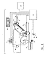
- working station 2 where a sheet of paper 4 is wound around a metal spindle 6 to produce primary roll 8. Also, there is shown working station 10 where primary roll 9 is unrolled to produce secondary roll 12. From one primary roll 9, several smaller secondary rolls 12 are produced to be delivered to clients. The final diameter D f of the primary roll 9 depends directly on the final diameter of the secondary rolls 12 to be delivered to the clients.
- paper sheet 4 can be torn or a portion of paper sheet 4 can have an unacceptable quality. All these factors have to be taken into consideration so that the primary roll 8 has a sufficient amount of paper to produce predetermined secondary rolls to be delivered to clients.
- the working stations 2 and 10 are provided with several equipments which comprise a computer 16, a terminal 18 disposed nearby an operator, an optical detector 20 for detecting the number of turns made by drum 22, an optical detector 24 for detecting the number of turns made by secondary roll 12, and another optical detector 26 for detecting the number of turns made by spindle 28.
- Paper sheet 4 coming from a paper machine (not shown) is moved around drum 30 to be wound around spindle 6.
- Spindle 6 is supported by means of rails 32.
- a constant pressure is applied on each side of the spindle 6 of primary roll 8 by means of cylinders 34. Only one cylinder 34 is shown in this figure, but it is understood that each side of spindle 6 is subjected to a pressure applied by a cylinder.
- Paper sheet 4 is wound around spindle 6 until the diameter of primary roll 8 reaches a predetermined value.
- the present system is capable of measuring the diameter of primary roll 8 in real time.
- the diameter of primary roll 8 is calculated from pulses received from detector 40 and detectors 42. Only one detector 42 is shown in Figure 2, but the other side of spindle 6 is also provided with a detector.
- Detector 40 generates a pulse during each turn of drum 30 and detectors 42 generate a pulse during each turn of spindle 6.
- a reflecting sticker 44 is stuck at each end of spindle 6 and is used to reflect an optical ray generated by detectors 42.
- one detector 42 receives a reflection from its corresponding sticker 44, it generates instantaneously an electric pulse which is sent to a computer 16 provided with an operating software. Only one of detectors 42 is used at the time. The second detector 42 is used as a back-up.
- computer 16 measures with precision the period of time between pulses generated by detectors 40 and 42 and calculates in real time the radius D of primary roll 8.
- T f D e [(T f D e )/T e ], where D is the diameter of primary roll 8, T f is the period of time measured between two pulses generated by detector 42, D e is the diameter of drum 30, and T e is the period of time measured between two pulses generated by detector 40.
- a display 50 showing the period of time remaining before the actual diameter of primary roll 8 reaches a predetermined diameter
- an alarm 52 a detector 54 detecting when paper sheet 4 is torn up
- a button 56 by which the operator can also indicate to computer 16 that paper sheet 4 is torn up
- another button 58 by which the operator can indicate to computer 16 that quality of paper is not acceptable
- a pressure detector 60 by which computer is informed of pressure applied by cylinders 34.
- diameters of secondary roll 12 and primary roll 9 of working station 10 can be determined in real time by optical means similar to the ones shown in Figure 2.
- the apparatus for producing first primary roll 8 having a predetermined lateral surface defined by lateral diameter D f is shown in Figures 1 and 2.
- the primary roll 8 is made of material wound around spindle 6.
- the material is used to produce smaller secondary rolls 12 of material.
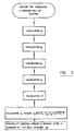
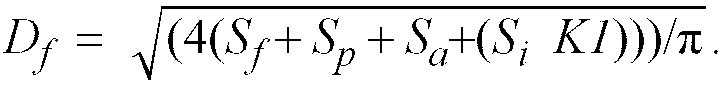
- the apparatus comprises means for calculating a portion S f of the lateral surface of primary roll, which is covered by its spindle. This means for calculating is performed by computer 16 and the calculation is done with respect to parameters entered by the operator by means of terminal 18.
- the apparatus also comprises means for calculating a portion S p of the lateral surface, which represents remaining unusable material wound around the spindle of primary roll. Again, this means for calculating is performed by computer 16 with respect to parameters entered by the operator.
- the apparatus also comprises means for calculating a portion S a of the lateral surface, which represents an error margin determined by the operator. Again, this error margin corresponds to parameters entered in computer 16 by the operator.
- the apparatus also comprises means for calculating a portion S i of the lateral surface which represents material needed to produce several smaller secondary rolls of material. This portion S i is calculated from parameters entered by the operator in computer 16.
- K [(sum of lateral surfaces of material of previous primary roll 9 used to produce previous secondary rolls 12)/(sum of lateral surfaces of material of said previous secondary rolls 12)].
- This means for calculating is performed by computer 16 by means of equipments at working station 10.
- This means for calculating D f is performed by computer 16.
- the apparatus also comprises means for winding up material around spindle 6 to produce primary roll 8 until its diameter reaches diameter D f .
- This means for winding up is situated at working station 2.
- the loss of material is reduced by taking into account compression factor K1 which varies with respect to time.
- the apparatus preferably comprises means for calculating at least another compression rate K of at least another primary roll with respect to previous secondary rolls, and means for calculating an average value of the compression rates K so that the compression factor K1 be derived from the average value.
- the above-mentioned means for calculating are performed by the computer 16 when successive primary rolls 9 are unrolled to produce secondary rolls 12 at working station 10.
- the operator determines, in an empirical manner, the diameter of primary roll 8 in function of the number and the size of secondary rolls to be delivered to clients. He also adds a security margin. Once primary roll 8 has a diameter which reaches the predetermined diameter, the operator transfers primary roll 8 from working station 2 to working station 10 where said primary roll becomes primary roll 9.
- first secondary roll 12 reaches a desired diameter, it is removed from working station 10, and paper sheet 14 is disposed around another spindle 13 to produce another secondary roll 12. This operation is repeated until primary roll 9 has not enough paper to produce another secondary roll 12. Then, the remaining amount of paper around spindle 28 is lost.
- the value of the compression factor K1 can be equal to the compression rate K or it can correspond to an average value of compression rates K calculated during successive unwinding of primary rolls 9.
- the method is for producing a primary roll 8 having a predetermined lateral surface defined by a diameter D f .
- the material will be used to produce smaller secondary rolls 12 of material.
- the compression factor K1 is calculated in real time each time that primary roll 9 is unrolled at working station 10.
- the measure of diameter of primary roll 9 and secondary roll 12 can be done by means of different optical means, mechanical means and electrical means. We will now describe one manner to determine the diameters of rolls 9 and 12.
- pulse generator 20 having a resolution of several pulses by turn, attached to drum 22, and by means of another pulse generator 26 having a resolution of one pulse by turn, attached to spindle 28, it is possible to calculate in real time the diameter of primary roll 9 at working station 10.
- S p [(( ⁇ (D p at the beginning) 2 )/4)-(( ⁇ (D p at the stop) 2 )/4)]
- S s [(( ⁇ (D s at the stop) 2 )/4)-(( ⁇ (D s at the beginning) 2 )/4)]
- S p is the lateral surface of material of primary roll 9, used for producing secondary roll 12
- D p are diameters at the beginning and at the stop of primary roll 9 when winding of secondary roll 12 begins and ends
- S s is the lateral surface of material of secondary roll 12
- D s are diameters at the beginning and at the stop of secondary roll 12.
- S p1 is the lateral surface removed from primary roll 9 during the winding of secondary roll 12, which has been used for producing S s1 of secondary roll 12.
- the number and the size of secondary rolls to be produced from primary roll 9 are entered by the operator in computer 16 by means of terminal 18. Then, it is possible to calculate in real time D f of the next primary roll 8 at working station 2 by taking into consideration the compression factor K1 calculated by computer 16. The calculation of D f can be done according to the equation mentioned earlier.
- D s3 and D p3 are 0.100m and 1.566m at the beginning, and 1.00m and 1.199m at the stop.
- D s4 and D p4 are 0.100m and 1.199m at the beginning, and are 1.000m and 0.650m at the stop.
- the spindle 6 mounted at the working station 2 has around it useless paper having a thickness of 0.025m. Accordingly, a quantity of paper equivalent to this useless paper has to be added to obtain enough paper for producing the three secondary rolls.
- the following parameters are entered by the operator at the terminal: diameter of the spindle 6 of primary roll 8, which is 0.600m; thickness of the useless paper present around the spindle 6, which is 0.025m; final diameters of three secondary rolls to be produced from this primary roll, each final diameter of the secondary rolls being 1.200m, diameter spindle of secondary rolls, which is 0.100m; and a security margin determined by the operator, which is 0.020m.
- the value of K1 is in the memory of the computer and has a value of 1.025.
- Computer 16 will now monitor in real time the winding of the next primary roll 8 at working station 2 and will stop the winding when the diameter of primary roll 8 will reach the value of D f .
- the present invention also comprises an apparatus for determining a value S d which is representative of an amount of material available on a first primary roll for producing first smaller secondary rolls.
- This first primary roll is previously produced by a given manufacturing process, has a diameter value D f and comprises a spindle which has a diameter value D sf .
- This apparatus is also shown in figures 1 and 2 and described hereinabove.
- the means for calculating the compression factor K 1 which is derived from a ratio R of a second primary roll used to produce smaller secondary rolls with respect to said second smaller secondary rolls, is performed by the computer 16 by means of equipments at working station 10.
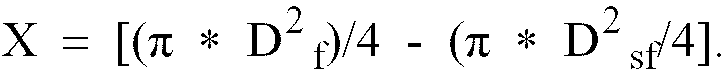
- this apparatus further comprises means for determining a value X which is representative of an amount of material wound around the spindle of the first primary roll by means of the diameter values D f and D sf .
- the values of the diameters D f and D sf can be determined by the aforesaid optical means.
- This means for determining the value X is performed by the computer 16 and is done with respect to parameters entered by the operator by means of terminal 18.
- the apparatus also comprises means for determining the value S d as a function of [(X - S p )/K 1 ] where S p is representative of an unusable amount of material on the first primary roll.
- This means for determining S d is performed by the computer 16 with respect to the parameters entered to the computer by the operator.
- the apparatus further comprises means for calculating a value S bstot which is representative of an amount of material needed to produce the first smaller secondary rolls. This means for calculating is performed by the computer 16, again with respect to the parameters entered by the operator. Furthermore, the apparatus comprises means for verifying whether the amount of material available on the first primary roll is sufficient to produce the first smaller secondary rolls by comparing the value S d to the value S bstot , and means for verifying whether the amount of material available on the first primary roll is sufficient to produce the first smaller secondary rolls where one or more of the first smaller secondary rolls have a reduced diameter which is equal to or greater than a predetermined acceptable reduced diameter value. In both cases, the apparatus can produce the first secondary rolls with the equipments at working station 10 if the amount of material available is sufficient. The means for verifying are performed by the computer 16.
- the apparatus comprises means for comparing a value D bsres which is representative of an amount of material which is left after producing the first smaller secondary rolls to a predetermined limit value.
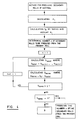
- the apparatus described hereinabove performs the following method for determining a value S d which is representative of an amount of material available on a first primary roll for producing first smaller secondary rolls.
- the method comprises steps of calculating K 1 ; determining a value X which is representative of an amount of material wound around the spindle of the first primary roll by means of the diameter values D f and D sf ; and determining the value S d as a function of [(X - S p )/K 1 ], where S p is representative of an unusable amount of material on the first primary roll.
- This method may comprise further steps for producing first smaller secondary rolls of material with given diameter values from the amount of material available on the first primary roll.
- the additional steps comprise steps of calculating a value S bstot which is representative of an amount of material needed to produce the first smaller secondary rolls; verifying whether the amount of material available on the first primary roll is sufficient to produce the first smaller secondary rolls by comparing the value S d to the value S bstot , and either producing the first secondary rolls if the amount of material available is sufficient, or else verifying whether the amount of material available on the first primary roll is sufficient to produce the first smaller secondary rolls where one or more of the first smaller secondary rolls have a reduced diameter which is equal to or greater than a predetermined acceptable reduced diameter value.
- the method further comprises the steps of producing the first smaller secondary rolls wherein at least one of the first smaller secondary rolls has the reduced diameter value if the amount of material available is sufficient, or else producing only the ones of the first smaller secondary rolls which can be completely produced with the given diameter values from the amount of material available on the first primary roll.
- the method may further comprise steps of comparing a value D bsres which is representative of the amount of material which is left after producing the ones of the first smaller secondary rolls with the given diameter values to a predetermined limit value, and either disposing the amount of material which is left if the value D bsres is smaller than the predetermined limit value, or recuperating the amount of material which is left by adding the amount of material which is left to a next primary roll.
- X [( ⁇ *D 2 f )/4 - ( ⁇ *D 2 sf )/4].
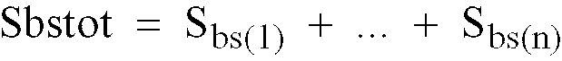
- S bstot S bs(1) +...+S bs(n)
- S bs(1) +...+S bs(n) is a sum of lateral surfaces of material of the first smaller secondary rolls which are n in number
- each of the lateral surfaces of the first smaller secondary rolls are calculated by means of the following equation:
- S bs(x) [ ⁇ (D 2 bs(x) -D 2 bss(x) )/4] where D bs(x) is a diameter value of the corresponding smaller secondary roll which is numbered by x, and D bss(x) is a diameter value of a spindle thereof.
- the apparatus performs a method which comprises steps of calculating the aforesaid compression factor K 1 which is derived from the ratio R of the second primary roll used to produce second smaller secondary rolls with respect to said second smaller secondary rolls, the second primary roll being also previously produced by the manufacturing process; determining a value X which is representative of an amount of material wound around the spindle of the first primary roll by means of the diameter values D f and D sf ; determining a value S p which is representative of an unusable amount of material on the first primary roll, the unusable amount of material being included in the amount of material available on the first primary roll; determining the value S d as a function of (X - S p ); calculating a value S bstot which is representative of an amount of material which is needed to produce the first smaller secondary rolls, the value S bstot being calculated by taking into account the compression factor K1; verifying whether the amount of material available on the first primary roll is sufficient to produce the first smaller secondary rolls
- the method further comprises the steps of producing the first smaller secondary rolls wherein at least one of the first smaller secondary rolls has the reduced diameter value if the amount of material available is sufficient, or else producing only the ones of the first smaller secondary rolls which can be completely produced with the given diameter values from the amount of material available on the first primary roll.
- the method may further comprise step of comparing a value D bsres which is representative of the amount of material which is left after producing the ones of the first smaller secondary rolls with the given diameter values to a predetermined limit value, and either disposing the amount of material which is left if the value D bsres is smaller than the predetermined limit value, or recuperating the amount of material which is left by adding the amount of material which is left to a next primary roll.
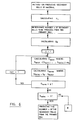
- the method according to the first embodiment comprises steps of calculating K 1 ; calculating the value S d as a function of [(X - S p )/K 1 ], where S p is representative of an unusable amount of material on the first primary roll and the value X is determined by means of diameter values D f and D sf as mentioned hereinbefore; and determining a number n of secondary rolls to be produced from the primary roll, each of the secondary rolls having a given diameter value.
- the method comprises the steps of calculating S bstot and calculating a value S bsres which is equal to (S d - S bstot ) and represents the amount of paper which is left, if there is any left, after producing the secondary rolls, the value S bstot being representative of the amount of material needed to produce smaller secondary rolls.
- the method also comprises a step of calculating a value S m which is representative of the amount of material which is needed in order to produce the last secondary roll of material with the given diameter value if the value S bsres is smaller than 0, meaning there is not enough of available material on the primary roll for producing all of the secondary rolls with given diameter values.
- the value S m is equal to 0 - S bsres .
- the method also comprises steps of adding each value N_D bsres to the aforesaid list D bsres [1...n] and verifying whether each of the stored values in the list D bsres [1...n] are greater than or equal to predetermined limit values. As shown, if the result of the test of verifying is positive, meaning the calculated reduced diameter values of one or more of the secondary rolls are acceptable and thus the secondary rolls can be produced with these reduced diameter values from the material available on the primary roll, the method comprises the step of producing the number n of these secondary rolls where one or more have the reduced diameter value.
- D bsres (n) 4 ⁇ S bs n ⁇ + D bss n 2 - 4 ⁇ S m ⁇
- the value D bsres (n) After the value D bsres (n) has been calculated, it is compared to a predetermined limit value and if the value D bsres (n) is greater than or equal to the pretermined limit value, only then the amount of material which is left can be recuperated, or else the material which is left has to be disposed.
- the method according to the alternative embodiment comprises steps of calculating K 1 ; calculating the value S d as a function of (X-S p ), where S p is representative of an unusable amount of material on the first primary roll and the value X is determined by means of diameter values D f and D sf as mentioned hereinbefore; and determining a number n of secondary rolls to be produced from the primary roll, each of the secondary rolls having a given diameter value.
- the method comprises the steps of calculating S bstot by taking into account the compression factor K 1 and calculating a value S bsres which is equal to (S d - S bstot ) and represents the amount of paper which is left, if there is any left, after producing the secondary rolls, the value S bstot being representative of the amount of material needed to produce smaller secondary rolls.
- the method comprises a step of calculating a value S m which is representative of the amount of material which is needed in order to produce the last secondary roll of material with the given diameter value if the value S bsres is smaller than 0, meaning there is not enough of available material on the primary roll for producing all of the secondary rolls with given diameter values.
- the method also comprises a step of adding each value N_D bsres (n) to the aforesaid list D bsres [1...n] and verifying whether each of the stored values in the list D bsres [1...n] are greater than or equal to predetermined limit values. If the result of the test of verifying is positive, meaning the calculated reduced diameter values of one or more of the secondary rolls are acceptable and the secondary rolls can be produced with these reduced diameter values from the material available on the primary roll, then the method further comprises the step of producing the number n of these secondary rolls where one or more have a reduced diameter value.
- the method further comprises the step of calculating the value D bsres (n), which is a value representing the amount of material left on the primary roll after producing only the ones of the smaller secondary rolls with the given diameter values.
- D bsres (n) is calculated with the following equation:
- the operator mounts this primary roll 9 at the working station 10 for producing smaller secondary rolls of paper.
- the operator by using the terminal 18, will instruct the computer 16 to evaluate the shortage of paper in the primary roll in order to complete all the desired secondary rolls (4*1,067).
- the computer will calculate the actual useful lateral surface of paper X which is wound around the spindle of the primary roll of paper:
- X [( ⁇ *D 2 f )/4 - ( ⁇ *D 2 sf )/4]
- X [( ⁇ *(2,078m) 2 )/4 - ( ⁇ *(0,0450m) 2 )/4]
- X 3,232m 2
- the next step for the operator is to determine whether he or she can complete the secondary rolls with the paper of the primary roll in a case where the diameter values of the secondary rolls are reduced within an acceptable limit.
- Most of the clients allow for the secondary rolls to have smaller dimensions than the dimensions they specified. However, there is an usual standard limit of approximately 0,012m. Therefore, the operator will instruct the terminal to apply a correction to the values of diameters of secondary rolls to lower the same in order to produce them, if possible, with the surface available on the primary roll.
- We will use the formula displayed in the algorithms to calculate the real diameter values of the secondary rolls to be produced therefrom. This is done in order to determine whether the secondary roll diameter values will respect the predetermined limits.
- D bsres ( x ) 4 ⁇ 0,886 m 2 ⁇ + 0,100 m 2 - 4 ⁇ 0,391 m 2 ⁇ (4-4+1)
- D bsres 0.800m
- the next step is to produce all the secondary rolls with the predetermined diameter values of 1,067m, except for the last one which will have a smaller diameter value. Because of the present system, the operator can determine in advance the amount of paper which he or she will have to add by gluing to the next primary roll of paper to complete the last secondary roll. By looking at the first calculation we did to evaluate the final diameter when the compensation is applied only to the last secondary roll, we see that we have for the last incomplete secondary roll a diameter value of 0,800m. Therefore, the operator has to instruct the computer to add an amount of paper necessary to complete the last incomplete secondary roll of paper to next primary roll, so that the diameter of the last incomplete secondary roll passes from 0,800m to 1,067m.
Landscapes
- Rolls And Other Rotary Bodies (AREA)
- Controlling Rewinding, Feeding, Winding, Or Abnormalities Of Webs (AREA)
- Paper (AREA)
- Reduction Rolling/Reduction Stand/Operation Of Reduction Machine (AREA)
- Diaphragms For Electromechanical Transducers (AREA)
Claims (26)
- Verfahren zur Herstellung einer Primärrolle (8) mit einer vorgegebenen seitlichen Oberfläche, die durch einen Durchmesser Df definiert ist, welche Primärrolle (8) aus Material (4) besteht, das auf eine Spindel (6) aufgewickelt ist und das zur Herstellung kleinerer Sekundärrollen (12) des Materials verwendet wird, welches Verfahren die Schritte aufweist: Berechnen des Oberflächenbereichs Sf der seitlichen Oberfläche, der von der Spindel (6) eingenommen wird, Berechnen des Oberflächenbereichs Si der seitlichen Oberfläche, der das zur Herstellung der kleineren Sekundärrollen (12) des Materials benötigte Material repräsentiert, und Aufwickeln von Material (4) auf die Spindel (6), bis der Durchmesser dieser Primärrolle (8) den Durchmesser Df erreicht, welches Verfahren dadurch gekennzeichnet ist, daß es vor dem Schritt des Aufwickelns die weiteren Schritte umfaßt:(a) Berechnen eines zeitlich veränderlichen Verdichtungsfaktors K1, der ein Verhältnis repräsentiert zwischen der eine vorherige Primärrolle bildenden Materialmenge und der Materialmenge, die vorherige Sekundärrollen bildet, die aus der vorherigen Primärrolle hergestellt sind, und(b) Berechnen von Df, wobei:

- Verfahren nach Anspruch 1, dadurch gekennzeichnet, daß es vor dem Schritt des Aufwickelns weiterhin die folgenden Schritte aufweist:Berechnen des Oberflächenbereichs Sp der seitlichen Oberfläche, der verbleibendes unbrauchbares Material auf der Spindel (6) repräsentiert,Berechnen des Oberflächenbereichs Sa der seitlichen Oberfläche, der eine durch einen Bediener bestimmte Fehlerzugabe repräsentiert, undin Schritt (b), Berechnen von Df, wobei:
- Verfahren nach Anspruch 1 oder 2, dadurch gekennzeichnet, daß der Verdichtungsfaktor K1 = [(Summe der seitlichen Oberflächen des Materials der vorherigen Primärrolle, das zur Herstellung der vorherigen Sekundärrollen verwendet wurde)/(Summe der seitlichen Oberflächen des Materials der vorherigen Sekundärrollen)].
- Verfahren nach Anspruch 1, 2 oder 3, dadurch gekennzeichnet, daß der Schritt (a) die weiteren Schritte aufweist:(i) Berechnen wenigstens eines weiteren Verdichtungsfaktors K1 wenigstens einer weiteren vorherigen Primärrolle in bezug auf andere vorherige Sekundärrollen und(ii) Berechnen eines Mittelwertes dieser Verdichtungsfaktoren und Verwenden des Mittelwertes als Verdichtungsfaktor K1.
- Verfahren nach Anspruch 1, dadurch gekennzeichnet, daß der Schritt des Aufwickelns weiterhin die folgenden Schritte aufweist:
Berechnen einer Materiallänge LBP, die zur Herstellung der Primärrolle (8) mit dem Durchmesserwert Df erforderlich ist, wobei diese Materiallänge LBP nach der folgenden Gleichung berechnet wird: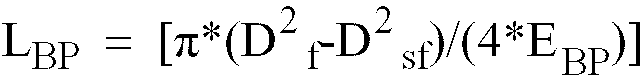
Aufwickeln der Materiallänge LBP auf die Spindel (6), um die Primärrolle (8) herzustellen. - Verfahren zur Bestimmung eines Wertes Sd, der eine Menge eines Materials (4) repräsentiert, die auf einer Primärrolle (8) zur Herstellung kleinerer Sekundärrollen (12) verfügbar ist, wobei die Primärrolle (8) zuvor durch einen gegebenen Herstellungsprozeß hergestellt worden ist, einen Durchmesserwert Df hat und eine Spindel (6) mit einem Durchmesserwert Dsf aufweist, welches Verfahren einen Schritt zur Bestimmung eines Wertes X, der eine auf die Spindel (6) der Primärrolle (8) aufgewickelte Menge an Material (4) repräsentiert, anhand der Durchmesserwerte Df und Dsf aufweist, welches Verfahren dadurch gekennzeichnet ist, daß es weiterhin die folgenden Schritte aufweist:(a) Berechnen eines zeitlich veränderlichen Verdichtungsfaktors K1, der repräsentativ ist für ein Verhältnis zwischen der eine vorherige Primärrolle bildenden Materialmenge und der Materialmenge, die vorherige kleinere Sekundärrollen bildet, die mit der vorherigen Primärrolle hergestellt worden sind, welche vorherige Primärrolle ebenfalls zuvor durch den Herstellungsprozeß hergestellt worden ist,(b) Bestimmen eines Wertes Sp, der eine unbrauchbare Menge an Material (4) auf der Primärrolle (8) repräsentiert, welche Menge an unbrauchbarem Material (4) in der auf der Primärrolle (8) verfügbaren Menge an Material (4) enthalten ist, und(c) Bestimmen des Wertes Sd als Funktion von [(X-Sp)/K1].
- Verfahren zur Herstellung kleinerer Sekundärrollen (12) von Material mit gegebenen Durchmesserwerten aus einer Menge an Material (4), das auf der Primärrolle (8) verfügbar ist, mit dem Schritt der Bestimmung des Wertes Sd nach Anspruch 6, welches Verfahren dadurch gekennzeichnet ist, daß es weiterhin die Schritte aufweist:(d) Berechnen eines Wertes Sbstot, der eine Menge an Material (4) repräsentiert, die zur Herstellung der kleineren Sekundärrollen (12) erforderlich ist,(e) Überprüfen, ob die Menge an Material (4), die auf der Primärrolle (8) verfügbar ist, zur Herstellung der kleineren Sekundärrollen (12) ausreicht, durch Vergleich des Wertes Sd mit dem Wert Sbstot, und entweder Herstellen der Sekundärrollen (12), wenn die verfügbare Menge an Material (4) ausreicht, oder Fortfahren mit Schritt (f) und(f) Überprüfen, ob die auf der Primärrolle (8) verfügbare Menge an Material (4) zur Herstellung der kleineren Sekundärrollen (12) ausreicht, wenn eine oder mehrere der kleineren Sekundärrollen (12) einen reduzierten Durchmesser haben, der größer oder gleich einem vorgegebenen akzeptablen reduzierten Durchmesserwert ist, und entweder Herstellen der kleineren Sekundärrollen (12), wobei wenigstens eine der kleineren Sekundärrollen (12) den reduzierten Durchmesserwert hat, wenn die Menge an verfügbarem Material (4) ausreicht, oder Herstellen nur derjenigen der kleineren Sekundärrollen (12), die mit den gegebenen Durchmesserwerten vollständig aus der auf der Primärrolle (8) verfügbaren Menge an Material (4) hergestellt werden können.
- Verfahren zur Herstellung kleinerer Sekundärrollen (12) aus Material mit gegebenen Durchmesserwerten aus einer auf einer Primärrolle (8) verfügbaren Menge an Material (4), welche Menge an Material (4) durch einen Wert Sd repräsentiert wird, wobei die Primärrolle (8) zuvor durch einen gegebenen Herstellungsprozeß hergestellt worden ist, einen Durchmesserwert Df hat und eine Spindel (6) mit einem Durchmesserwert Dsf aufweist, welches Verfahren die Schritte aufweist: Bestimmen eines Wertes X, der eine Menge an auf die Spindel (6) der ersten Primärrolle (8) aufgewickeltem Material (4) repräsentiert, anhand der Durchmesserwerte Df und Dsf, und Berechnen eines Wertes Sbstot, der eine Menge an Material (4) repräsentiert, die zur Herstellung der kleineren Sekundärrollen (12) erforderlich ist, welches Verfahren dadurch gekennzeichnet ist, daß es weiterhin die Schritte aufweist:(a) Berechnen eines zeitlich veränderlichen Verdichtungsfaktors K1, der repräsentativ ist für ein Verhältnis zwischen der Menge an eine vorherige Primärrolle bildendem Material und der Menge an Material, die vorherige kleinere Sekundärrollen bildet, die aus der vorherigen Primärrolle hergestellt wurden, wobei die vorherige Primärrolle ebenfalls zuvor durch den Herstellungsprozeß hergestellt worden ist,(b) Bestimmen eines Wertes Sp, der eine unbrauchbare Menge an Material (4) auf der Primärrolle (8) repräsentiert, welche Menge an unbrauchbarem Material (4) in der Menge an auf der Primärrolle (8) verfügbarem Material (4) enthalten ist,(c) Bestimmen des Wertes Sd als Funktion von [(X-Sp),(d) wobei in dem Schritt der Berechnung des Wertes von Sbstot dieser Wert Sbstot unter Berücksichtigung des Verdichtungsfaktors K1 berechnet wird,(e) Überprüfen, ob die Menge an auf der Primärrolle (8) verfügbarem Material (4) zur Herstellung der kleineren Sekundärrollen (12) ausreicht, durch Vergleich des Wertes Sd mit dem Wert Sbstot, und entweder Herstellen der Sekundärrollen (12), wenn die Menge an verfügbarem Material (4) ausreicht, oder Fortfahren mit Schritt (f) und(f) Überprüfen, ob die Menge an auf der Primärrolle (8) verfügbarem Material (4) zur Herstellung der kleineren Sekundärrollen (12) ausreicht, wenn eine oder mehrere dieser kleineren Sekundärrollen (12) einen reduzierten Durchmesserwert haben, der unter Berücksichtigung von K1 bestimmt wird und größer oder gleich einem vorgegebenen akzeptablen reduzierten Durchmesserwert ist, und entweder Herstellen der kleineren Sekundärrollen (12), bei denen wenigstens eine der kleineren Sekundärrollen (12) den reduzierten Durchmesserwert hat, wenn die Menge an verfügbarem Material (4) ausreicht, oder Herstellen nur derjenigen der kleineren Sekundärrollen (12), die mit den gegebenen Durchmesserwerten vollständig aus der auf der Primärrolle (8) verfügbaren Menge an Material (4) hergestellt werden können.
- Verfahren nach Anspruch 7 oder 8, dadurch gekennzeichnet, daß es nach dem Schritt der Überprüfung, ob die auf der Primärrolle (8) verfügbare Menge an Material (4) zur Herstellung der kleineren Sekundärrollen (12) ausreicht, den Schritt des Vergleichs eines Wertes Dbsres, der eine nach der Herstellung derjenigen der kleineren Sekundärrollen (12) mit den gegebenen Durchmesserwerten übriggebliebene Menge an Material (4) repräsentiert, mit einem vorgegebenen Grenzwert und entweder der Entsorgung der übriggebliebenen Menge an Material (4), wenn dieser Wert Dbsres kleiner ist als der vorgegebene Grenzwert, oder der Wiederverwertung der übriggebliebenen Menge an Material (4) aufweist, durch Hinzufügen dieser Menge an übriggebliebenem Material (4) zu einer nächsten Primärrolle (8).
- Verfahren nach Anspruch 6 oder 8, dadurch gekennzeichnet, daß, in Schritt (a), der Verdichtungsfaktor K1 = [(eine seitliche Oberfläche von Material der vorherigen Primärrolle, das zur Herstellung der vorherigen kleineren Sekundärrollen verwendet wurde)/(Summe von seitlichen Oberflächen von Material der vorherigen kleineren Sekundärrollen)).
- Verfahren nach Anspruch 6 oder 8, dadurch gekennzeichnet, daß bei dem Schritt der Bestimmung des Wertes X dieser Wert X nach der folgenden Gleichung bestimmt wird:
- Verfahren nach Anspruch 7 oder 8, dadurch gekennzeichnet, daß bei dem Schritt der Berechnung des Wertes Sbstot dieser Wert Sbstot nach der folgenden Gleichung berechnet wird:

- Vorrichtung zur Herstellung einer Primärrolle (8) mit einer vorgegebenen seitlichen Oberfläche, die durch einen seitlichen Durchmesser Df definiert ist, welche Primärrolle (8) aus auf eine Spindel (6) aufgewickeltem Material (4) besteht, wobei das Material (4) zur Herstellung kleinerer Sekundärrollen (12) des Materials verwendet wird, welche Vorrichtung aufweist: Mittel zur Berechnung des Oberflächenbereichs Sf der seitlichen Oberfläche, der von der Spindel (6) eingenommen wird, Mittel zur Berechnung des Oberflächenbereichs Si der seitlichen Oberfläche, der das zur Herstellung der kleineren Sekundärrollen (12) des Materials benötigte Material (4) repräsentiert, und Mittel zum Aufwickeln von Material auf die Spindel (6) zur Herstellung der Primärrolle (8), welche Vorrichtung dadurch gekennzeichnet ist, daß sie weiterhin aufweist:Mittel zur Berechnung eines zeitlich veränderlichen Verdichtungsfaktors K1, der repräsentativ ist für ein Verhältnis zwischen der Menge an eine vorherige Primärrolle bildendem Material und der Menge an Material, das vorherige Sekundärrollen bildet, die aus der vorherigen Primärrolle hergestellt wurden, undMittel zur Berechnung von Df, wobei:

- Vorrichtung nach Anspruch 13, dadurch gekennzeichnet, daß sie weiterhin aufweist:Mittel zur Berechnung des Oberflächenbereichs Sp der seitlichen Oberfläche, der verbleibendes unbrauchbares Material (4) auf der Spindel (6) repräsentiert,Mittel zur Berechnung des Oberflächenbereichs Sa der seitlichen Oberfläche, der eine durch einen Bediener bestimmte Fehlerzugabe repräsentiert, undMittel zur Berechnung von Df, wobei:

- Vorrichtung nach Anspruch 13 oder 14, dadurch gekennzeichnet, daß der Verdichtungsfaktor K1 = [(Summe der seitlichen Oberflächen von Material der vorherigen Primärrolle, die zur Herstellung der vorherigen Sekundärrollen verwendet wurde)/(Summe der seitlichen Oberflächen von Material der vorherigen Sekundärrollen)].
- Vorrichtung nach Anspruch 13, 14 oder 15, dadurch gekennzeichnet, daß sie weiterhin aufweist:Mittel zur Berechnung wenigstens eines weiteren Verdichtungsfaktors K1 wengistens einer anderen vorherigen Primärrolle in bezug auf andere vorherige Sekundärrollen undMittel zur Berechnung eines Mittelwertes der Verdichtungsfaktoren, so daß der Verdichtungsfaktor K1, der zur Berechnung von Df berechnet wird, dieser Mittelwert ist.
- Vorrichtung zur Bestimmung eines Wertes Sd, der eine Menge an Material (4) repräsentiert, das auf einer Primärrolle (8) zur Herstellung kleinerer Sekundärrollen (12) verfügbar ist, welche Primärrolle (8) zuvor durch einen gegebenen Herstellungsprozeß hergestellt worden ist, einen Durchmesserwert Df hat und eine Spindel (6) mit einem Durchmesserwert Dsf aufweist, welche Vorrichtung Mittel aufweist zur Bestimmung eines Wertes X, der eine auf die Spindel (6) der Primärrolle (8) aufgewickelte Menge an Material (4) repräsentiert, anhand der Durchmesserwerte Df und Dsf, wobei die Vorrichtung dadurch gekennzeichnet ist, daß sie weiterhin aufweist:Mittel zur Berechnung eines zeitlich veränderlichen Verdichtungsfaktors K1, der repräsentativ ist für ein Verhältnis zwischen der Menge an eine vorherige Primärrolle (8) bildendem Material und der Menge an Material, das vorherige kleinere Sekundärrollen (12) bildet, die aus der vorherigen Primärrolle hergestellt wurden, wobei die vorherige Primärrolle (8) ebenfalls zuvor durch den Herstellungsprozeß hergestellt worden ist, undMittel zur Bestimmung des Wertes Sd als Funktion von [(X-Sp)/K1), wobei Sp eine unbrauchbare Menge an Material (4) auf der Primärrolle (8) repräsentiert.
- Vorrichtung zur Herstellung kleinerer Sekundärrollen (12) von Material mit gegebenen Durchmesserwerten aus einer Menge an Material (4), das auf der Primärrolle (8) verfügbar ist, mit einer Vorrichtung zur Bestimmung des Wertes Sd nach Anspruch 17, welche Vorrichtung dadurch gekennzeichnet ist, daß sie weiterhin aufweist:Mittel zur Berechnung eines Wertes Sbstot, der eine Menge an Material (4) repräsentiert, die zur Herstellung der kleineren Sekundärrollen (12) erforderlich ist,Mittel zur Überprüfung, ob die auf der Primärrolle (8) verfügbare Menge an Material (4) zur Herstellung der Sekundärrollen (12) ausreicht, durch Vergleich des Wertes Sd mit dem Wert Sbstot,Mittel zur Überprüfung, ob die auf der Primärrolle (8) verfügbare Menge an Material (4) zur Herstellung der kleineren Sekundärrollen (12) ausreicht, wenn eine oder mehrere der kleineren Sekundärrollen (12) einen reduzierten Durchmesser haben, der größer oder gleich einem vorgegebenen akzeptablen reduzierten Durchmesserwert ist,Mittel zur Herstellung der kleineren Sekundärrollen (12), bei denen wenigstens eine der kleineren Sekundärrollen (12) den reduzierten Durchmesserwert hat, wenn die Menge an verfügbarem Material (4) ausreicht, undMittel zur Herstellung nur derjenigen der kleineren Sekundärrollen (12), die mit den gegebenen Durchmesserwerten vollständig aus der auf der Primärrolle (8) verfügbaren Menge an Material (4) hergestellt werden können, wenn diese Menge an Material (4) nicht ausreicht.
- Vorrichtung zur Herstellung kleinerer Sekundärrollen (12) von Material mit gegebenen Durchmesserwerten aus einer auf einer Primärrolle (8) verfügbaren Menge an Material (4), welche Menge an Material (4) durch einen Wert Sd repräsentiert wird, wobei die Primärrolle (8) zuvor durch einen gegebenen Herstellungsprozeß hergestellt worden ist, einen Durchmesserwert Df hat und eine Spindel (6) mit einem Durchmesserwert Dsf aufweist, welche Vorrichtung Mittel aufweist zur Bestimmung eines Wertes X, der eine auf die Spindel (6) der Primärrolle (8) aufgewickelte Menge an Material (4) repräsentiert, anhand der Durchmesserwerte Df und Dsf, und Mittel zur Berechnung eines Wertes Sbstot, der eine Menge an Material (4) repräsentiert, die zur Herstellung der kleineren Sekundärrollen (12) benötigt wird, welche Vorrichtung dadurch gekennzeichnet ist, daß sie weiterhin aufweist:die genannten Mittel zur Berechnung des Wertes Sbstot, der unter Berücksichtigung des Verdichtungsfaktors K1 berechnet wird,Mittel zur Berechnung eines zeitlich veränderlichen Verdichtungsfaktors K1, der repräsentativ ist für ein Verhältnis zwischen der Menge an eine vorherige Primärrolle (8) bildendem Material und der Menge an Material, das vorherige kleinere Sekundärrollen (12) bildet, die aus der vorherigen Primärrolle hergestellt wurden, wobei die vorherige Primärrolle (8) ebenfalls zuvor durch den Herstellungsprozeß hergestellt worden ist,Mittel zur Bestimmung des Wertes Sd als Funktion von (X-Sp), wobei Sp eine unbrauchbare Menge an Material (4) auf der Primärrolle (8) repräsentiert,Mittel zur Überprüfung, ob die auf der Primärrolle (8) verfügbare Menge an Material (4) zur Herstellung der kleineren Sekundärrollen (12) ausreicht, durch Vergleich des Wertes Sd mit dem Wert Sbstot,Mittel zur Überprüfung, ob die auf der Primärrolle (8) verfügbare Menge an Material (4) zur Herstellung der kleineren Sekundärrollen (12) ausreicht, wenn eine oder mehrere der kleineren Sekundärrollen (12) einen reduzierten Durchmesserwert haben, der unter Berücksichtigung von K1 bestimmt ist und größer oder gleich einem vorgegebenen akzeptablen reduzierten Durchmesserwert ist,Mittel zur Herstellung der kleineren Sekundärrollen (12), bei denen wenigstens eine der kleineren Sekundärrollen (12) den reduzierten Durchmesserwert hat, wenn die verfügbare Menge an Material (4) ausreicht, undMittel zur Herstellung nur derjenigen der kleineren Sekundärrollen (12), die mit den gegebenen Durchmesserwerten vollständig aus der auf der Primärrolle (8) verfügbaren Menge an Material (4) hergestellt werden können, wenn diese Menge an Material (4) nicht ausreicht.
- Vorrichtung nach Anspruch 18 oder 19, dadurch gekennzeichnet, daß sie weiterhin Mittel aufweist zum Vergleich eines Wertes Dbsres, der eine Menge an Material (4) repräsentiert, die nach der Herstellung derjenigen der kleineren Sekundärrollen (12) mit den gegebenen Durchmesserwerten übriggeblieben ist, mit einem vorgegebenen Grenzwert, zur Bestimmung, ob das übriggebliebene Material (4) wiederverwertet werden kann.
- Vorrichtung nach Anspruch 17 oder 19, dadurch gekennzeichnet, daß der Verdichtungsfaktor K1 = [(Summe aus seitlichen Oberflächen von Material der vorherigen Primärrolle, die zur Herstellung der vorherigen kleineren Sekundärrollen verwendet wurde)/(Summe der seitlichen Oberflächen von Material der vorherigen kleineren Sekundärrollen)].
- Vorrichtung nach Anspruch 17 oder 19, dadurch gekennzeichnet, daß die Mittel zur Bestimmung des Wertes X Mittel aufweisen zur Berechnung des Wertes X nach der folgenden Gleichung:
- Vorrichtung nach Anspruch 18 oder 19, dadurch gekennzeichnet, daß:
die Mittel zur Berechnung des Wertes Sbstot die folgende Gleichung benutzen:
die Mittel zur Berechnung des Wertes Sbstot Mittel aufweisen zur Berechnung jeder der seitlichen Oberflächen der kleineren Sekundärrollen (12) nach der folgenden Gleichung:
- Vorrichtung nach Anspruch 17 oder 19, dadurch gekennzeichnet, daß die Mittel zur Berechnung des Verdichtungsfaktors K1, die Mittel zur Bestimmung des Wertes X und die Mittel zur Bestimmung des Wertes Sd sämtlich Teil eines Computers mit einer Betriebssoftware sind.
- Vorrichtung nach Anspruch 17 oder 19, dadurch gekennzeichnet, daß die Mittel zur Berechnung des Wertes Sbstot und die Mittel zur Überprüfung sämtlich Teile eines Computers mit einer Betriebssoftware sind.
- Vorrichtung nach Anspruch 20, dadurch gekennzeichnet, daß die Vergleichsmittel Teile eines Computers mit einer Betriebssoftware sind.
Applications Claiming Priority (3)
| Application Number | Priority Date | Filing Date | Title |
|---|---|---|---|
| US69942 | 1993-05-28 | ||
| US08/069,942 US5402353A (en) | 1993-05-28 | 1993-05-28 | Method and apparatus for producing a primary roll of material |
| PCT/CA1994/000298 WO1994027901A1 (en) | 1993-05-28 | 1994-05-26 | Method and apparatus for producing a primary roll of material, or for determining an amount of material available on a primary roll |
Publications (2)
| Publication Number | Publication Date |
|---|---|
| EP0700359A1 EP0700359A1 (de) | 1996-03-13 |
| EP0700359B1 true EP0700359B1 (de) | 1997-08-06 |
Family
ID=22092160
Family Applications (1)
| Application Number | Title | Priority Date | Filing Date |
|---|---|---|---|
| EP94916862A Expired - Lifetime EP0700359B1 (de) | 1993-05-28 | 1994-05-26 | Verfahren und gerät zur herstellung einer primärrolle aus material oder zur bestimmung der auf einer primärrolle verfügbaren materialmenge |
Country Status (9)
| Country | Link |
|---|---|
| US (1) | US5402353A (de) |
| EP (1) | EP0700359B1 (de) |
| AT (1) | ATE156455T1 (de) |
| AU (1) | AU6840094A (de) |
| CA (1) | CA2158348C (de) |
| DE (1) | DE69404839T2 (de) |
| FI (1) | FI117090B (de) |
| NO (1) | NO305938B1 (de) |
| WO (1) | WO1994027901A1 (de) |
Families Citing this family (6)
| Publication number | Priority date | Publication date | Assignee | Title |
|---|---|---|---|---|
| US5806785A (en) * | 1993-05-28 | 1998-09-15 | Recherche D.C.B.L. Inc./D.C.B.L. Research Inc. | Method and apparatus for producing a primary roll of material or for determining an amount of material available on a primary roll |
| CN1202868A (zh) * | 1995-11-28 | 1998-12-23 | 法比奥-泼尼股份公司 | 测量网材卷直径的方法和装置 |
| BR9815782A (pt) * | 1998-03-31 | 2000-11-28 | Siemens Ag | Processo e disposição para modelagem neuronal de um dispositivo de bobinagem de papel |
| JP4148459B2 (ja) * | 2000-12-27 | 2008-09-10 | セイコーエプソン株式会社 | 印刷装置、印刷方法及び印刷用記録媒体 |
| DE102005024091A1 (de) * | 2005-05-25 | 2006-11-30 | Man Roland Druckmaschinen Ag | Verfahren und Vorrichtung zum Umspulen eines Bandes |
| US8032246B2 (en) * | 2007-02-02 | 2011-10-04 | Kimberly-Clark Worldwide, Inc. | Winding method for uniform properties |
Family Cites Families (13)
| Publication number | Priority date | Publication date | Assignee | Title |
|---|---|---|---|---|
| US3792820A (en) * | 1972-03-01 | 1974-02-19 | Beloit Corp | Web rewinder |
| GB1461343A (en) * | 1973-02-03 | 1977-01-13 | Agfa Gevaert Ag | Automatic film-cassette fabrication |
| US4021002A (en) * | 1975-06-23 | 1977-05-03 | Butler Automatic, Inc. | Auto-splice system |
| US4519039A (en) * | 1982-07-23 | 1985-05-21 | Westinghouse Electric Corp. | Digital coil diameter function generator and reel motor drive system embodying the same |
| US4535950A (en) * | 1984-01-13 | 1985-08-20 | International Paper Company | Method and apparatus for roll winding measurement |
| GB8407465D0 (en) * | 1984-03-22 | 1984-05-02 | Rieter Ag Maschf | Length control in winding of threads |
| US4631682A (en) * | 1984-08-07 | 1986-12-23 | Beloit Corporation | Method and apparatus for controlling a winder for stop-to-length or stop-to-roll diameter |
| FI81770C (fi) * | 1987-05-20 | 1990-12-10 | Valmet Paper Machinery Inc | Foerfarande vid styrning av pappers rullstol. |
| JPH0455000Y2 (de) * | 1987-11-02 | 1992-12-24 | ||
| US4811915A (en) * | 1987-11-12 | 1989-03-14 | The Black Clawson Company | Rider roll relieving system |
| IT1222185B (it) * | 1988-01-29 | 1990-09-05 | Perini Finanziaria Spa | Congegno per il controllo della produzione di rotoli di carta prodotti dalla ribobinatrice per assicurare costanza di lunghezza della carta avvolta e/o del diametro raggiunto |
| CA1330839C (en) * | 1989-08-30 | 1994-07-19 | Douglas Edward Turek | Method of predicting yarn package size |
| US5042736A (en) * | 1989-09-26 | 1991-08-27 | Kabushiki Kaisha Toshiba | Apparatus for production of thin strip core, method for the production of a thin strip core and thin strip core |
-
1993
- 1993-05-28 US US08/069,942 patent/US5402353A/en not_active Expired - Lifetime
-
1994
- 1994-05-26 DE DE69404839T patent/DE69404839T2/de not_active Expired - Lifetime
- 1994-05-26 EP EP94916862A patent/EP0700359B1/de not_active Expired - Lifetime
- 1994-05-26 AT AT94916862T patent/ATE156455T1/de not_active IP Right Cessation
- 1994-05-26 WO PCT/CA1994/000298 patent/WO1994027901A1/en not_active Ceased
- 1994-05-26 AU AU68400/94A patent/AU6840094A/en not_active Abandoned
- 1994-05-26 CA CA002158348A patent/CA2158348C/en not_active Expired - Lifetime
-
1995
- 1995-10-16 NO NO954102A patent/NO305938B1/no not_active IP Right Cessation
- 1995-10-25 FI FI955095A patent/FI117090B/fi not_active IP Right Cessation
Also Published As
| Publication number | Publication date |
|---|---|
| DE69404839D1 (de) | 1997-09-11 |
| NO954102D0 (no) | 1995-10-16 |
| WO1994027901A1 (en) | 1994-12-08 |
| NO954102L (no) | 1995-10-16 |
| DE69404839T2 (de) | 1998-02-05 |
| EP0700359A1 (de) | 1996-03-13 |
| CA2158348C (en) | 1996-11-12 |
| US5402353A (en) | 1995-03-28 |
| AU6840094A (en) | 1994-12-20 |
| CA2158348A1 (en) | 1994-12-08 |
| FI955095A0 (fi) | 1995-10-25 |
| NO305938B1 (no) | 1999-08-23 |
| FI955095A7 (fi) | 1995-10-25 |
| FI117090B (fi) | 2006-06-15 |
| ATE156455T1 (de) | 1997-08-15 |
Similar Documents
| Publication | Publication Date | Title |
|---|---|---|
| EP0700359B1 (de) | Verfahren und gerät zur herstellung einer primärrolle aus material oder zur bestimmung der auf einer primärrolle verfügbaren materialmenge | |
| MXPA04011706A (es) | Sistema de control y ajuste del enrollado de un producto para el consumidor. | |
| US5806785A (en) | Method and apparatus for producing a primary roll of material or for determining an amount of material available on a primary roll | |
| US4660365A (en) | Method and apparatus for determining yarn number or thickness deviations | |
| US4337903A (en) | Method of and a device for controlling the exchange of rolls of a web-like material | |
| ITMI971084A1 (it) | Procedimento e dispositivo per produrre una bobina | |
| CA2097246C (en) | Method and apparatus for producing a primary roll of material | |
| US7070141B2 (en) | Method for controlling winder | |
| US11078041B2 (en) | Monitoring method for monitoring an unwinding process, unwinding device and unwinding system | |
| US4951893A (en) | Method and apparatus for splicing webs | |
| US11148894B2 (en) | Method and devices and system for winding and unwinding a reel | |
| JP3305652B2 (ja) | コイル材の巻き込み空気量測定方法及び測定装置 | |
| JPH11263493A (ja) | 抄紙機制御装置 | |
| JP3089800B2 (ja) | シートの無引張シート幅計測方法及び無引張シート幅計測装置 | |
| EP3889084A1 (de) | Stütz- und rotationsgruppe für eine rolle, maschine mit solch einer gruppe, verfahren zur verfolgung eines materials, das auf einer rolle in besagter gruppe aufgewickelt ist | |
| JP2528362B2 (ja) | 巻取製品の不良除去位置指示方法 | |
| EP0735343A1 (de) | Diameterüberwachungssystem | |
| JP2021138492A (ja) | シート体の不良箇所除去方法、及び巻取装置 | |
| JPS60262778A (ja) | 定量糸条巻取方法および装置 | |
| KR100549348B1 (ko) | 광섬유 권취를 위한 자동 제어 장치 및 이를 이용한 제어 방법 | |
| JPH08231099A (ja) | 多軸装置の軸切り替え制御装置 | |
| JPH08174027A (ja) | 可逆式圧延機の溶接点自動減速方法 | |
| JPH0776465A (ja) | あや巻きボビン巻回体を形成するせんい機械の生産能力を求める方法 | |
| JPH08127446A (ja) | 不良除去方法および装置 | |
| JP2914570B2 (ja) | 線材の検査及び切割装置 |
Legal Events
| Date | Code | Title | Description |
|---|---|---|---|
| PUAI | Public reference made under article 153(3) epc to a published international application that has entered the european phase |
Free format text: ORIGINAL CODE: 0009012 |
|
| 17P | Request for examination filed |
Effective date: 19951018 |
|
| AK | Designated contracting states |
Kind code of ref document: A1 Designated state(s): AT BE CH DE DK ES FR GB GR IE IT LI LU MC NL PT SE |
|
| GRAG | Despatch of communication of intention to grant |
Free format text: ORIGINAL CODE: EPIDOS AGRA |
|
| 17Q | First examination report despatched |
Effective date: 19960722 |
|
| GRAH | Despatch of communication of intention to grant a patent |
Free format text: ORIGINAL CODE: EPIDOS IGRA |
|
| GRAH | Despatch of communication of intention to grant a patent |
Free format text: ORIGINAL CODE: EPIDOS IGRA |
|
| GRAA | (expected) grant |
Free format text: ORIGINAL CODE: 0009210 |
|
| AK | Designated contracting states |
Kind code of ref document: B1 Designated state(s): AT BE CH DE DK ES FR GB GR IE IT LI LU MC NL PT SE |
|
| PG25 | Lapsed in a contracting state [announced via postgrant information from national office to epo] |
Ref country code: NL Free format text: LAPSE BECAUSE OF FAILURE TO SUBMIT A TRANSLATION OF THE DESCRIPTION OR TO PAY THE FEE WITHIN THE PRESCRIBED TIME-LIMIT Effective date: 19970806 Ref country code: IT Free format text: LAPSE BECAUSE OF FAILURE TO SUBMIT A TRANSLATION OF THE DESCRIPTION OR TO PAY THE FEE WITHIN THE PRESCRIBED TIME-LIMIT;WARNING: LAPSES OF ITALIAN PATENTS WITH EFFECTIVE DATE BEFORE 2007 MAY HAVE OCCURRED AT ANY TIME BEFORE 2007. THE CORRECT EFFECTIVE DATE MAY BE DIFFERENT FROM THE ONE RECORDED. Effective date: 19970806 Ref country code: GR Free format text: LAPSE BECAUSE OF FAILURE TO SUBMIT A TRANSLATION OF THE DESCRIPTION OR TO PAY THE FEE WITHIN THE PRESCRIBED TIME-LIMIT Effective date: 19970806 Ref country code: FR Free format text: LAPSE BECAUSE OF FAILURE TO SUBMIT A TRANSLATION OF THE DESCRIPTION OR TO PAY THE FEE WITHIN THE PRESCRIBED TIME-LIMIT Effective date: 19970806 Ref country code: ES Free format text: THE PATENT HAS BEEN ANNULLED BY A DECISION OF A NATIONAL AUTHORITY Effective date: 19970806 Ref country code: DK Free format text: LAPSE BECAUSE OF NON-PAYMENT OF DUE FEES Effective date: 19970806 Ref country code: BE Effective date: 19970806 Ref country code: AT Effective date: 19970806 |
|
| REF | Corresponds to: |
Ref document number: 156455 Country of ref document: AT Date of ref document: 19970815 Kind code of ref document: T |
|
| REG | Reference to a national code |
Ref country code: CH Ref legal event code: EP |
|
| REG | Reference to a national code |
Ref country code: CH Ref legal event code: NV Representative=s name: A. BRAUN, BRAUN, HERITIER, ESCHMANN AG PATENTANWAE |
|
| REF | Corresponds to: |
Ref document number: 69404839 Country of ref document: DE Date of ref document: 19970911 |
|
| PG25 | Lapsed in a contracting state [announced via postgrant information from national office to epo] |
Ref country code: PT Effective date: 19971113 |
|
| EN | Fr: translation not filed | ||
| NLV1 | Nl: lapsed or annulled due to failure to fulfill the requirements of art. 29p and 29m of the patents act | ||
| PG25 | Lapsed in a contracting state [announced via postgrant information from national office to epo] |
Ref country code: LU Free format text: LAPSE BECAUSE OF NON-PAYMENT OF DUE FEES Effective date: 19980526 Ref country code: IE Free format text: LAPSE BECAUSE OF NON-PAYMENT OF DUE FEES Effective date: 19980526 Ref country code: GB Free format text: LAPSE BECAUSE OF NON-PAYMENT OF DUE FEES Effective date: 19980526 |
|
| PLBE | No opposition filed within time limit |
Free format text: ORIGINAL CODE: 0009261 |
|
| STAA | Information on the status of an ep patent application or granted ep patent |
Free format text: STATUS: NO OPPOSITION FILED WITHIN TIME LIMIT |
|
| REG | Reference to a national code |
Ref country code: CH Ref legal event code: PFA Free format text: HTRC AUTOMATION INC. TRANSFER- D.C.B.L. INC./D.C.B.L. RESEARCH INC. |
|
| 26N | No opposition filed | ||
| PG25 | Lapsed in a contracting state [announced via postgrant information from national office to epo] |
Ref country code: MC Free format text: LAPSE BECAUSE OF NON-PAYMENT OF DUE FEES Effective date: 19981130 |
|
| GBPC | Gb: european patent ceased through non-payment of renewal fee |
Effective date: 19980526 |
|
| REG | Reference to a national code |
Ref country code: CH Ref legal event code: PFA Owner name: RECHERCHE D.C.B.L. INC./D.C.B.L. RESEARCH INC. Free format text: RECHERCHE D.C.B.L. INC./D.C.B.L. RESEARCH INC.#285 LAVAL B.P. 990#BROMPTONVILLE/QUEBEC J0B 1HO (CA) -TRANSFER TO- RECHERCHE D.C.B.L. INC./D.C.B.L. RESEARCH INC.#285 LAVAL B.P. 990#BROMPTONVILLE/QUEBEC J0B 1HO (CA) |
|
| PGFP | Annual fee paid to national office [announced via postgrant information from national office to epo] |
Ref country code: DE Payment date: 20130611 Year of fee payment: 20 Ref country code: CH Payment date: 20130613 Year of fee payment: 20 Ref country code: SE Payment date: 20130517 Year of fee payment: 20 |
|
| REG | Reference to a national code |
Ref country code: DE Ref legal event code: R071 Ref document number: 69404839 Country of ref document: DE |
|
| REG | Reference to a national code |
Ref country code: CH Ref legal event code: PL |
|
| REG | Reference to a national code |
Ref country code: SE Ref legal event code: EUG |
|
| PG25 | Lapsed in a contracting state [announced via postgrant information from national office to epo] |
Ref country code: DE Free format text: LAPSE BECAUSE OF EXPIRATION OF PROTECTION Effective date: 20140527 |