EP0699881B1 - Kühlsystem zum Abkühlen eines Kühlobjektes auf tiefe Temperaturen mittels eines Joule-Thomson-Kühlers - Google Patents
Kühlsystem zum Abkühlen eines Kühlobjektes auf tiefe Temperaturen mittels eines Joule-Thomson-Kühlers Download PDFInfo
- Publication number
- EP0699881B1 EP0699881B1 EP95116849A EP95116849A EP0699881B1 EP 0699881 B1 EP0699881 B1 EP 0699881B1 EP 95116849 A EP95116849 A EP 95116849A EP 95116849 A EP95116849 A EP 95116849A EP 0699881 B1 EP0699881 B1 EP 0699881B1
- Authority
- EP
- European Patent Office
- Prior art keywords
- memory element
- temperature
- shape memory
- joule
- shape
- Prior art date
- Legal status (The legal status is an assumption and is not a legal conclusion. Google has not performed a legal analysis and makes no representation as to the accuracy of the status listed.)
- Expired - Lifetime
Links
- 238000001816 cooling Methods 0.000 title claims description 24
- 238000005057 refrigeration Methods 0.000 title 1
- 230000006835 compression Effects 0.000 claims description 8
- 238000007906 compression Methods 0.000 claims description 8
- 238000010438 heat treatment Methods 0.000 claims description 6
- 239000013078 crystal Substances 0.000 description 10
- 230000009466 transformation Effects 0.000 description 7
- 230000008859 change Effects 0.000 description 4
- 229910045601 alloy Inorganic materials 0.000 description 2
- 239000000956 alloy Substances 0.000 description 2
- 238000006243 chemical reaction Methods 0.000 description 2
- 238000006073 displacement reaction Methods 0.000 description 2
- 230000009471 action Effects 0.000 description 1
- 229910001566 austenite Inorganic materials 0.000 description 1
- 230000006399 behavior Effects 0.000 description 1
- 238000009835 boiling Methods 0.000 description 1
- 239000002826 coolant Substances 0.000 description 1
- 238000010586 diagram Methods 0.000 description 1
- 230000010339 dilation Effects 0.000 description 1
- 230000000694 effects Effects 0.000 description 1
- 229910000734 martensite Inorganic materials 0.000 description 1
- 229910001092 metal group alloy Inorganic materials 0.000 description 1
- 229910001000 nickel titanium Inorganic materials 0.000 description 1
- 230000009467 reduction Effects 0.000 description 1
- 230000000630 rising effect Effects 0.000 description 1
- 238000004904 shortening Methods 0.000 description 1
- 230000007704 transition Effects 0.000 description 1
Images

Classifications
-
- G—PHYSICS
- G01—MEASURING; TESTING
- G01J—MEASUREMENT OF INTENSITY, VELOCITY, SPECTRAL CONTENT, POLARISATION, PHASE OR PULSE CHARACTERISTICS OF INFRARED, VISIBLE OR ULTRAVIOLET LIGHT; COLORIMETRY; RADIATION PYROMETRY
- G01J5/00—Radiation pyrometry, e.g. infrared or optical thermometry
- G01J5/02—Constructional details
- G01J5/04—Casings
- G01J5/041—Mountings in enclosures or in a particular environment
-
- F—MECHANICAL ENGINEERING; LIGHTING; HEATING; WEAPONS; BLASTING
- F25—REFRIGERATION OR COOLING; COMBINED HEATING AND REFRIGERATION SYSTEMS; HEAT PUMP SYSTEMS; MANUFACTURE OR STORAGE OF ICE; LIQUEFACTION SOLIDIFICATION OF GASES
- F25B—REFRIGERATION MACHINES, PLANTS OR SYSTEMS; COMBINED HEATING AND REFRIGERATION SYSTEMS; HEAT PUMP SYSTEMS
- F25B9/00—Compression machines, plants or systems, in which the refrigerant is air or other gas of low boiling point
- F25B9/02—Compression machines, plants or systems, in which the refrigerant is air or other gas of low boiling point using Joule-Thompson effect; using vortex effect
-
- G—PHYSICS
- G01—MEASURING; TESTING
- G01J—MEASUREMENT OF INTENSITY, VELOCITY, SPECTRAL CONTENT, POLARISATION, PHASE OR PULSE CHARACTERISTICS OF INFRARED, VISIBLE OR ULTRAVIOLET LIGHT; COLORIMETRY; RADIATION PYROMETRY
- G01J5/00—Radiation pyrometry, e.g. infrared or optical thermometry
- G01J5/02—Constructional details
- G01J5/06—Arrangements for eliminating effects of disturbing radiation; Arrangements for compensating changes in sensitivity
- G01J5/061—Arrangements for eliminating effects of disturbing radiation; Arrangements for compensating changes in sensitivity by controlling the temperature of the apparatus or parts thereof, e.g. using cooling means or thermostats
-
- G—PHYSICS
- G05—CONTROLLING; REGULATING
- G05D—SYSTEMS FOR CONTROLLING OR REGULATING NON-ELECTRIC VARIABLES
- G05D23/00—Control of temperature
- G05D23/19—Control of temperature characterised by the use of electric means
- G05D23/1919—Control of temperature characterised by the use of electric means characterised by the type of controller
-
- G—PHYSICS
- G05—CONTROLLING; REGULATING
- G05D—SYSTEMS FOR CONTROLLING OR REGULATING NON-ELECTRIC VARIABLES
- G05D23/00—Control of temperature
- G05D23/19—Control of temperature characterised by the use of electric means
- G05D23/1919—Control of temperature characterised by the use of electric means characterised by the type of controller
- G05D23/1921—Control of temperature characterised by the use of electric means characterised by the type of controller using a thermal motor
-
- G—PHYSICS
- G05—CONTROLLING; REGULATING
- G05D—SYSTEMS FOR CONTROLLING OR REGULATING NON-ELECTRIC VARIABLES
- G05D23/00—Control of temperature
- G05D23/19—Control of temperature characterised by the use of electric means
- G05D23/1925—Control of temperature characterised by the use of electric means using a combination of auxiliary electric and non-electric power
-
- G—PHYSICS
- G05—CONTROLLING; REGULATING
- G05D—SYSTEMS FOR CONTROLLING OR REGULATING NON-ELECTRIC VARIABLES
- G05D23/00—Control of temperature
- G05D23/19—Control of temperature characterised by the use of electric means
- G05D23/20—Control of temperature characterised by the use of electric means with sensing elements having variation of electric or magnetic properties with change of temperature
-
- F—MECHANICAL ENGINEERING; LIGHTING; HEATING; WEAPONS; BLASTING
- F25—REFRIGERATION OR COOLING; COMBINED HEATING AND REFRIGERATION SYSTEMS; HEAT PUMP SYSTEMS; MANUFACTURE OR STORAGE OF ICE; LIQUEFACTION SOLIDIFICATION OF GASES
- F25B—REFRIGERATION MACHINES, PLANTS OR SYSTEMS; COMBINED HEATING AND REFRIGERATION SYSTEMS; HEAT PUMP SYSTEMS
- F25B2309/00—Gas cycle refrigeration machines
- F25B2309/02—Gas cycle refrigeration machines using the Joule-Thompson effect
- F25B2309/022—Gas cycle refrigeration machines using the Joule-Thompson effect characterised by the expansion element
Definitions
- the invention relates to a cooling system for cooling a Cooling object to low temperatures using a Joule-Thomson cooler with an expansion nozzle, in which a Electrical temperature sensor is provided, which is immediate responds to the temperature of the cooling object and at which means the flow through the expansion nozzle of a throttle body is adjustable by an actuator is adjustable depending on the temperature, that of the electrical Temperature sensor is controllable in the sense of a Increasing the flow when the temperature of the Cooling object beyond a setpoint.
- GB-A-1 238 470 includes a Joule-Thomson cooler an expansion nozzle known, in which the flow through the expansion nozzle by means of a throttle body is adjustable.
- the throttle body is from an actuator adjustable depending on temperature.
- the actuator consists of an operating rod and a bellows.
- the throttle body is attached to the operating rod.
- the temperature of the The cooling object is controlled by a thermo-electric temperature sensor measured.
- the actuator is from this temperature sensor controllable via a preamplifier and a controller, the pressure on the via an electro-pneumatic valve Outside of the bellows affected. This will make the effective opening area of the expansion nozzle is changed and hence the flow of the coolant.
- EP-A-0 245 164 describes a Joule-Thomson cooler with expansion nozzle and one with an actuator connected closure element.
- the actuator is designed so that it is the closure element at a certain temperature suddenly from a first to a second position moves. In the first position that leaves Closure element completely opening the expansion nozzle free. In the second position, the closure element closes the opening of the expansion nozzle partially and leaves at the edge open a small leak passage at the opening.
- the Expansion nozzle on a side wall of a bore In this Hole is the cylindrical, in the bore rotatable closure element.
- the closure element has an oblique notch. If the Opening of the expansion nozzle is aligned with this notch, it is open, otherwise closed.
- the closure element is from the actuator depending on the temperature turned.
- the actuator consists of a bimetal strip of two attached to each other Plates, namely a thin, helical at rest twisted plate made of an alloy with high Resistance and a slightly thicker plate from one Alloy with shape memory properties. Above one certain transformation temperature is the thicker plate plastic and keeps the bimetallic strip in a plan Shape.
- the thicker Plate suddenly elastic, so that the bimetallic strip assumes the helical shape of the thinner plate. This conversion is subject to hysteresis. On in this way the closure element when reaching the The transformation temperature suddenly twists and closes the opening of the expansion nozzle. The cooling capacity drops this and the bimetal strip becomes warmer again. On Because of the shape memory property of the thicker plate the bimetallic strip takes one with respect to the Transformation temperature shifted by the hysteresis Now heat the flat shape again.
- JP-A-61 017788 Patent Abstracts of Japan, vol. 10, no. 167
- a valve opening is opened by a valve closing member and is closed.
- the valve closing member is with a Shape memory element connected in the form of a plate, by which an electrical current can be conducted. If no current flows through the plate, it is convexly curved and the valve closing member is in an open position. If a current flows through the plate, the plate becomes flat and the valve closing member is then in one Closed position.
- Embodiments of the invention are the subject of the independent Expectations.
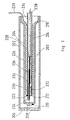
- 200 denotes a dewar.
- the Dewar jar 200 has an outer part 202 and one for it coaxial inner part 204.
- Outer and inner part 202 or 204 are cup-shaped and with each other at their open ends connected.
- the outer part 202 forms on its closed A window 206 on the front side.
- On the front side of the inner part 204 sits a cooling object in the form of an infrared sensitive Detector 208.
- A sits on the detector 208 Temperature sensor 210.
- a Joule-Thomson cooler 212 sits in the Dewar vessel 200.
- Tube 214 is a compressed gas line 216 helical wound up.
- the compressed gas line 216 is with heat exchanger fins 218 provided.
- On the compressed gas line becomes a compressed gas via a compressed gas connection 220 headed.
- On the detector side the compressed gas line ends in one Expansion nozzle 222.
- the outlet cross section of the Relaxation nozzle 222 is through a throttle body 224 changeable.
- the throttle body 224 is seated on a tension member 226
- Tension member 226 is on its throttle body 224 facing away End connected to tube 214 via webs 228.
- a Plate 230 attached to the throttle body end of the tension member 226 .
- the compression spring 232 is a coil spring that is arranged coaxially to the tension member 226.
- the compression spring 232 is supported on a spring abutment 234.
- the spring abutment 234 sits in the tube 214.
- the tension member 226 is passed centrally through the spring abutment 234. On in this way the tension member 226 is by the compression spring 232 curious; excited.
- the compression spring 232 searches for the throttle body 224 in to press his open position.
- a section is switched into the tension member 226 which is formed by a shape memory element 236.
- the shape memory element 236 can be heated in that a Line 238 a heating current through the shape memory element 236 is passed through.
- Shape memory elements are bodies that depend on their crystal structure (austenite or martensite) their Dimensions, e.g. their length, between a first and change a second value.
- the transformation of the crystal structures takes place depending on the temperature.
- the body either only one or only the other crystal structure the dimensions of the body change a lot strongly with the temperature. It can be within a Temperature range in which the conversion between the Crystal structures take place, changes in length up to 3% occur. That is orders of magnitude more than normal thermal expansion of a body.
- Such shape memory elements are known and commercially available available. They are metal alloys, for example NiTi, CuZnAl or CuAlNi.
- FIG. Fig. 2 is a shape change diagram of a shape memory element.
- the abscissa is the temperature in K
- the ordinate is the change in length.
- the length of the shape memory element initially remains at an essentially constant value, which is represented by the horizontal curve profile 240.
- a transformation of the crystal structure of the shape memory element begins, which is associated with a large reduction in the length of the shape memory element. This is illustrated by the curve course 242 falling towards lower temperatures.
- the shape memory element has the other crystal structure throughout. With further cooling, the length of the shape memory element then remains essentially constant. This is shown by the horizontal curve 244.
- the shape memory element initially retains the crystal structure assigned to the lower temperatures.
- the length remains essentially constant up to a point A s .
- point A s a transformation into the crystal structure assigned to the higher temperatures begins.
- the length of the shape memory element increases again with increasing temperature up to a point A f .
- curve shape 248 is essentially parallel to the curve shape 242.
- the length of the shape memory element then remains essentially constant again at temperatures above A f . This is shown by curve 250.
- the shape memory element 236 is in the cooling system of Fig.1 dimensioned so that at higher temperatures Throttle 224 from the compression spring 224 in its full open position is pressed.
- the shape memory element then shows the crystal structure according to the curve shape 250 from Fig. 2. So it gets full opened expansion nozzle 222 a maximum cooling rate reached.
- the temperature of the detector 208 becomes quickly degraded.
- the length of the shape memory element 236 is initially only insignificantly corresponding to the usual thermal dilation shortened.
- the shape memory element 236 is selected so that the temperature to which the detector 208 is to be cooled, in which Area in which the one with a sharp shortening of the shape memory element associated transition from the one crystal structure to another.
- the shape memory element 236 is also cooled by the back-flowing, relaxed gas. This shortens the shape memory element 236.
- the throttle member 224 is pulled against the action of the compression spring 232 to the right in FIG. 1 and throttles the expansion nozzle 222. The cooling effect is thus reduced. After the "cooldown", a temperature T c arises, as shown in FIG.
- the shape memory element 236 is fully expanded at temperatures above 170 K.
- the shape memory element 236 is then located at point A f in FIG. 3.
- a temperature T c of between 90 and 120 K is established at the sensor 210.
- the shape memory element 236 is then located in the area of the horizontal curve between the points M f and A s .
- a setpoint temperature lies in the middle of the working range between the points M f and A f, which is determined by the falling and rising curve profiles 242 and 248.
- the shape memory element 236 is heated by passing electrical current through it.
- the state of the shape memory element 236 then moves on the curve 248 between the points A s and A f .
- the temperature at detector 208 drops until the boiling temperature of the expanding gas is reached at point 252 at detector 208. (This is not the temperature of the shape memory element assigned to point 252 in FIG. 3). Then there is no further cooling of the sensor.
- the heating current is through the shape memory element 236 switched off.
- the shape memory element is cooled 236 along the dashed line in Fig.3 shown curve shape 254, wherein the length of the shape memory element 236 and thus the temperature of the Detector 208 remains substantially constant.
- the shape memory element 236 is shortened.
- the expansion nozzle 222 throttled more.
- this causes an increase that at the detector 208 by the temperature sensor 210 measured temperature.
- the controller switches the heating current again.
- the temperature of the shape memory element 236 increases. This follows the state of the shape memory element 236 the dashed Curve course 256.
- the length of the shape memory element remains 236 again essentially unchanged, until curve point 248 is reached again at point 258 and the length of the shape memory element 236 becomes that Point 252 enlarged again.
- the active control element very easy.
- the active control element consists of only one spring-biased wire with the shape memory element, which is also formed by a piece of wire.
- the actuator is capable of relatively large actuating forces of more than 2N with a wire thickness of the shape memory element 236 of 0.2 mm wire thickness.
- At a Length of the shape memory element of 10 mm can be an adjustment stroke of more than 100 ⁇ m can be achieved.
- the work area can be chosen within wide limits.
Landscapes
- Physics & Mathematics (AREA)
- Engineering & Computer Science (AREA)
- General Physics & Mathematics (AREA)
- Automation & Control Theory (AREA)
- Spectroscopy & Molecular Physics (AREA)
- Mechanical Engineering (AREA)
- Thermal Sciences (AREA)
- General Engineering & Computer Science (AREA)
- Power Engineering (AREA)
- Investigating Or Analyzing Materials Using Thermal Means (AREA)
- Control Of Temperature (AREA)
- Temperature-Responsive Valves (AREA)
Description
- Fig.1
- zeigt einen Längsschnitt eines mit einem Joule-Thomson-Kühler arbeitenden, geregelten Kühlsystems, bei welchem als Stellglied ein beheizbares Formgedächtniselement dient.
- Fig.2
- zeigt die Temperatur-Weg-Kennlinie des Formgedächtniselements für Erwärmung und Abkühlung.
- Fig.3
- veranschaulicht das Regelprinzip für die Temperatur des Kühlobjekts in der Temperatur-Weg-Kennlinie des als Stellglied dienenden Formgedächtniselements.
Claims (3)
- Kühlsystem zum Abkühlen eines Kühlobjektes (208) auf tiefe Temperaturen mittels eines Joule-Thomson-Kühlers (212) mit einer Expansionsdüse (222), bei welchem ein elektrischer Temperatursensor (210) vorgesehen ist, der unmittelbar auf die Temperatur des Kühlobjektes (208) anspricht und bei welchem der Durchfluß durch die Expansionsdüse (222) mittels eines Drosselkörpers (224) regelbar ist, der von einem Stellglied temperaturabhängig verstellbar ist, das von dem elektrischen Temperatursensor (210) steuerbar ist im Sinne einer Erhöhung des Durchflusses bei Erhöhung der Temperatur des Kühlobjektes (208) über einen Sollwert hinaus, dadurch gekennzeichnet, daß das Stellglied ein nach Maßgabe eines Stellsignals des Temperatursensors (210) beheizbares Formgedächtniselement (236) aufweist, welches von einem Draht gebildet ist, der sich innerhalb des Joule-Thomson-Kühlers erstreckt.
- Kühlsystem nach Anspruch 1, dadurch gekennzeichnet, daß(a) das Stellglied ein Zugglied (226) aufweist, der sich längs des Joule-Thomson-Kühlers erstreckt, an seinem detektorseitigen Ende den Drosselkörper (224) trägt und durch eine Druckfeder (232) in Öffnungsrichtung des Drosselkörpers (224) vorgespannt ist, und(b) das Formgedächtniselement (236) einen Teil des Zugglieds (226) bildet.
- Kühlsystem nach Anspruch 1 oder 2, dadurch gekennzeichnet, daß zum Beheizen des Formgedächtniselements (236) ein Heizstrom unmittelbar durch das Formgedächtniselement (236) hindurchleitbar ist.
Applications Claiming Priority (3)
| Application Number | Priority Date | Filing Date | Title |
|---|---|---|---|
| DE4226820 | 1992-08-13 | ||
| DE4226820A DE4226820A1 (de) | 1992-08-13 | 1992-08-13 | Kühlsystem zum Abkühlen eines Kühlobjektes auf tiefe Temperaturen mittels eines Joule-Thomson-Kühlers |
| EP93110156A EP0582817B1 (de) | 1992-08-13 | 1993-06-25 | Kühlsystem zum Abkühlen eines Kühlobjektes auf tiefe Temperaturen mittels eines Joule-Thomson-Kühlers |
Related Parent Applications (2)
| Application Number | Title | Priority Date | Filing Date |
|---|---|---|---|
| EP93110156A Division EP0582817B1 (de) | 1992-08-13 | 1993-06-25 | Kühlsystem zum Abkühlen eines Kühlobjektes auf tiefe Temperaturen mittels eines Joule-Thomson-Kühlers |
| EP93110156.2 Division | 1993-06-25 |
Publications (3)
| Publication Number | Publication Date |
|---|---|
| EP0699881A2 EP0699881A2 (de) | 1996-03-06 |
| EP0699881A3 EP0699881A3 (de) | 1996-09-11 |
| EP0699881B1 true EP0699881B1 (de) | 1999-01-13 |
Family
ID=6465488
Family Applications (3)
| Application Number | Title | Priority Date | Filing Date |
|---|---|---|---|
| EP93110156A Expired - Lifetime EP0582817B1 (de) | 1992-08-13 | 1993-06-25 | Kühlsystem zum Abkühlen eines Kühlobjektes auf tiefe Temperaturen mittels eines Joule-Thomson-Kühlers |
| EP95116849A Expired - Lifetime EP0699881B1 (de) | 1992-08-13 | 1993-06-25 | Kühlsystem zum Abkühlen eines Kühlobjektes auf tiefe Temperaturen mittels eines Joule-Thomson-Kühlers |
| EP95116848A Expired - Lifetime EP0699880B1 (de) | 1992-08-13 | 1993-06-25 | Kühlsystem zum Abkühlen eines im Mantelhohlraum eines Dewargefässes angeordneten Sensors |
Family Applications Before (1)
| Application Number | Title | Priority Date | Filing Date |
|---|---|---|---|
| EP93110156A Expired - Lifetime EP0582817B1 (de) | 1992-08-13 | 1993-06-25 | Kühlsystem zum Abkühlen eines Kühlobjektes auf tiefe Temperaturen mittels eines Joule-Thomson-Kühlers |
Family Applications After (1)
| Application Number | Title | Priority Date | Filing Date |
|---|---|---|---|
| EP95116848A Expired - Lifetime EP0699880B1 (de) | 1992-08-13 | 1993-06-25 | Kühlsystem zum Abkühlen eines im Mantelhohlraum eines Dewargefässes angeordneten Sensors |
Country Status (2)
| Country | Link |
|---|---|
| EP (3) | EP0582817B1 (de) |
| DE (4) | DE4226820A1 (de) |
Families Citing this family (14)
| Publication number | Priority date | Publication date | Assignee | Title |
|---|---|---|---|---|
| FR2718224B1 (fr) * | 1994-03-31 | 1996-04-26 | Cryotechnologies | Procédé de régulation thermique d'un mini-refroidisseur Joule-Thomson. |
| FR2725013B1 (fr) * | 1994-09-22 | 1996-12-13 | Air Liquide | Refroidisseur joule-thomson |
| AU5238396A (en) * | 1995-06-06 | 1996-12-19 | Hughes Missile Systems Company | Adaptive orifice Joule-Thomson cryostat with servo-control |
| US5548963A (en) * | 1995-06-08 | 1996-08-27 | Hughes Missile Systems Company | Joule-Thompson cryostat for use with multiple coolants |
| US6016659A (en) * | 1997-10-30 | 2000-01-25 | Raytheon Co. | Reactive thermo elastic cryostat |
| DE19812725A1 (de) | 1998-03-24 | 1999-09-30 | Bodenseewerk Geraetetech | Verfahren und Vorrichtung zum Kühlen von Bauteilen, insbesondere von Infrarot-Detektoren bei Suchköpfen |
| US6082119A (en) * | 1999-02-16 | 2000-07-04 | General Pneumatics Corp. | Commandably actuated cryostat |
| DE102008014003B4 (de) * | 2008-03-13 | 2010-02-11 | Bundesrepublik Deutschland, vertr.d.d. Bundesministerium für Wirtschaft und Technologie, d.vertr.d.d. Präsidenten der Physikalisch-Technischen Bundesanstalt | Kryosensorpositioniervorrichtung und kryostatische Anlage |
| IL208627A0 (en) * | 2010-10-11 | 2010-12-30 | Rafael Advanced Defense Sys | Regulated joule thompson cooling system which comprises an active closed control loop for increasing reliability and preventing instantaneous overheating |
| EP3002569B1 (de) | 2014-09-18 | 2017-06-07 | Diehl Defence GmbH & Co. KG | Kühlvorrichtung |
| US10072877B2 (en) | 2014-09-18 | 2018-09-11 | Diehl Defence Gmbh & Co. Kg | Cooling device |
| CN106369892B (zh) * | 2016-11-16 | 2019-06-14 | 昆明物理研究所 | 一种应用于微型节流制冷器的回流稳压结构 |
| FR3061769B1 (fr) * | 2017-01-10 | 2020-11-13 | Safran Electronics & Defense | Module de detection infrarouge refroidi par refroidisseur de type joule thomson |
| CN108181004B (zh) * | 2017-12-22 | 2020-06-12 | 烟台艾睿光电科技有限公司 | 一种红外热成像仪 |
Family Cites Families (26)
| Publication number | Priority date | Publication date | Assignee | Title |
|---|---|---|---|---|
| GB238470A (en) | 1925-02-14 | 1925-08-20 | James Henry Cartner Boyd | Improvements in and relating to perambulators and the like |
| US3324674A (en) * | 1966-01-03 | 1967-06-13 | Texas Instruments Inc | Refrigeration control apparatus |
| US3942010A (en) * | 1966-05-09 | 1976-03-02 | The United States Of America As Represented By The Secretary Of The Navy | Joule-Thomson cryostat cooled infrared cell having a built-in thermostat sensing element |
| US3413819A (en) * | 1966-05-09 | 1968-12-03 | Hughes Aircraft Co | Flow rate control for a joule-thomson refrigerator |
| GB1238470A (de) * | 1968-06-28 | 1971-07-07 | ||
| US3464227A (en) * | 1968-07-22 | 1969-09-02 | Controls Co Of America | Expansion valve and heat pump system |
| US3640091A (en) * | 1969-05-13 | 1972-02-08 | Santa Barbara Res Center | Valve arrangement to provide temperature level control at cryogenic temperature ranges |
| FR2322337A1 (fr) * | 1975-08-26 | 1977-03-25 | Air Liquide | Dispositif d'alimentation de refrigerant d'un refrigerateur a circuit ouvert, et systeme de refrigeration comportant un tel dispositif |
| GB2085139A (en) * | 1980-10-10 | 1982-04-21 | Hymatic Engineering The Co Ltd | Cryogenic cooling apparatus |
| EP0098646A3 (de) * | 1982-07-05 | 1985-05-22 | Leuven Research & Development V.Z.W. | Kälteempfindliches Relais |
| DE3314576A1 (de) * | 1983-04-22 | 1984-10-25 | Licentia Patent-Verwaltungs-Gmbh, 6000 Frankfurt | Verfahren und vorrichtung zur kuehlung von optoelektronischen sensoren, insbesondere von ir-detektoren |
| US4617593A (en) * | 1984-08-07 | 1986-10-14 | Texas Instruments Incorporated | Visible and near infrared imaging system |
| JPS61227141A (ja) * | 1985-03-29 | 1986-10-09 | Furukawa Electric Co Ltd:The | NiTi系形状記憶合金線 |
| FR2598206B1 (fr) * | 1986-05-05 | 1988-07-08 | Air Liquide | Refroidisseur joule-thomson. |
| US4786809A (en) * | 1986-07-31 | 1988-11-22 | Santa Barbara Reseach Center | Low noise preamplification stage |
| GB8619437D0 (en) * | 1986-08-08 | 1986-09-17 | Bradley L | Storage & refrigeration |
| GB2193799A (en) * | 1986-08-11 | 1988-02-17 | Hymatic Eng Co Ltd | Cryogenic cooling apparatus |
| GB8628610D0 (en) * | 1986-11-29 | 1987-01-07 | Emi Plc Thorn | Temperature sensing arrangement |
| US4755676A (en) * | 1986-12-19 | 1988-07-05 | Hughes Aircraft Company | Infrared detector with improved heat dissipation |
| US4868902A (en) * | 1988-02-03 | 1989-09-19 | Hughes Aircraft Company | GaAs capacitive feedback transimpedance amplifier |
| JPH02221823A (ja) * | 1989-02-22 | 1990-09-04 | Hitachi Ltd | 光度計 |
| FR2645256B1 (fr) * | 1989-03-15 | 1994-12-23 | Air Liquide | Refroidisseur joule-thomson a deux debits |
| JPH042929A (ja) * | 1990-04-19 | 1992-01-07 | Minolta Camera Co Ltd | 赤外線検出装置 |
| GB9025485D0 (en) * | 1990-11-23 | 1991-01-09 | Thorn Emi Electronics Ltd | Joule thomson apparatus |
| US5119637A (en) * | 1990-12-28 | 1992-06-09 | The United States Of America As Represented By The Administrator Of The National Aeronautics And Space Administration | Ultra-high temperature stability Joule-Thomson cooler with capability to accommodate pressure variations |
| JPH06117788A (ja) * | 1992-10-02 | 1994-04-28 | Matsushita Refrig Co Ltd | 熱交換器 |
-
1992
- 1992-08-13 DE DE4226820A patent/DE4226820A1/de not_active Ceased
-
1993
- 1993-06-25 DE DE59304031T patent/DE59304031D1/de not_active Expired - Lifetime
- 1993-06-25 EP EP93110156A patent/EP0582817B1/de not_active Expired - Lifetime
- 1993-06-25 DE DE59309315T patent/DE59309315D1/de not_active Expired - Lifetime
- 1993-06-25 EP EP95116849A patent/EP0699881B1/de not_active Expired - Lifetime
- 1993-06-25 DE DE59309314T patent/DE59309314D1/de not_active Expired - Lifetime
- 1993-06-25 EP EP95116848A patent/EP0699880B1/de not_active Expired - Lifetime
Also Published As
| Publication number | Publication date |
|---|---|
| DE59309314D1 (de) | 1999-02-25 |
| EP0699880B1 (de) | 1999-01-13 |
| EP0582817A1 (de) | 1994-02-16 |
| EP0699880A2 (de) | 1996-03-06 |
| EP0699881A2 (de) | 1996-03-06 |
| EP0699881A3 (de) | 1996-09-11 |
| DE59309315D1 (de) | 1999-02-25 |
| DE59304031D1 (de) | 1996-11-07 |
| EP0582817B1 (de) | 1996-10-02 |
| DE4226820A1 (de) | 1994-02-17 |
| EP0699880A3 (de) | 1996-09-11 |
Similar Documents
| Publication | Publication Date | Title |
|---|---|---|
| EP0699881A2 (de) | Kühlsystem zum Abkühlen eines Kühlobjektes auf tiefe Temperaturen mittels eines Joule-Thomson-Kühlers | |
| DE10300487B4 (de) | Kühlvorrichtung sowie Thermostat mit einer solchen Kühlvorrichtung | |
| DE2715718C2 (de) | Elektromagnetisches Ventil | |
| DE4242848C2 (de) | Kälteanlage und Verfahren zur Steuerung einer Kälteanlage | |
| DE60308538T2 (de) | Ventil für Raumfahrtanwendungen mit SMA-AKTOR | |
| DE3922591C2 (de) | ||
| EP0356642B1 (de) | Thermostatisches Expansionsventil | |
| DE2134409C3 (de) | Thermostatisches Expansionsventil für ein Kühlsystem | |
| DE2259807C2 (de) | Kryogenes Kühlsystem | |
| DE2419515A1 (de) | Ventilbaugruppe insbesondere zur verwendung in einem kuehlsystem | |
| DE1775805A1 (de) | Drosselventil,insbesondere zur Steuerung eines stroemenden Kaeltemittels | |
| DE19727440A1 (de) | Kühlmittelausdehnungseinrichtung | |
| DE2111667B2 (de) | Thermostatisches Ventil | |
| DE2354889A1 (de) | Durchflussregelventil | |
| DE69810268T2 (de) | Kühlgerät mit einem druckbetätigten durchflussregler für einen joule-thomson kryostat | |
| DE9218709U1 (de) | Wärme- und Strömungsregulator mit integrierter Strömungs-Optimiereinrichtung | |
| DE102008018639A1 (de) | Thermostatische Regeleinrichtung | |
| WO2008074383A1 (de) | Thermostatisches expansionsventil | |
| DE102008038310A1 (de) | Kryochirurgisches Gerät zum Betreiben von Kryosonden, Verfahren zum Betreiben einer Kryosonde | |
| DE69810074T2 (de) | Reaktiver thermoelastischer kryostat | |
| DE102009011611A1 (de) | Gasregelarmatur | |
| DE10228510B4 (de) | Ventil für einen Türschließer | |
| DE2613991B1 (de) | Thermostatische betaetigungsvorrichtung fuer ein heizmittelventil | |
| EP0735450A2 (de) | Thermostatventil für eine Fussbodenheizung | |
| DE102008031584B4 (de) | Anordnung zum Verstellen eines Ventils |
Legal Events
| Date | Code | Title | Description |
|---|---|---|---|
| PUAI | Public reference made under article 153(3) epc to a published international application that has entered the european phase |
Free format text: ORIGINAL CODE: 0009012 |
|
| AC | Divisional application: reference to earlier application |
Ref document number: 582817 Country of ref document: EP |
|
| AK | Designated contracting states |
Kind code of ref document: A2 Designated state(s): DE FR GB |
|
| PUAL | Search report despatched |
Free format text: ORIGINAL CODE: 0009013 |
|
| AK | Designated contracting states |
Kind code of ref document: A3 Designated state(s): DE FR GB |
|
| 17P | Request for examination filed |
Effective date: 19960905 |
|
| 17Q | First examination report despatched |
Effective date: 19980115 |
|
| GRAG | Despatch of communication of intention to grant |
Free format text: ORIGINAL CODE: EPIDOS AGRA |
|
| GRAG | Despatch of communication of intention to grant |
Free format text: ORIGINAL CODE: EPIDOS AGRA |
|
| GRAH | Despatch of communication of intention to grant a patent |
Free format text: ORIGINAL CODE: EPIDOS IGRA |
|
| GRAH | Despatch of communication of intention to grant a patent |
Free format text: ORIGINAL CODE: EPIDOS IGRA |
|
| GRAA | (expected) grant |
Free format text: ORIGINAL CODE: 0009210 |
|
| AC | Divisional application: reference to earlier application |
Ref document number: 582817 Country of ref document: EP |
|
| AK | Designated contracting states |
Kind code of ref document: B1 Designated state(s): DE FR GB |
|
| ET | Fr: translation filed | ||
| REF | Corresponds to: |
Ref document number: 59309315 Country of ref document: DE Date of ref document: 19990225 |
|
| GBT | Gb: translation of ep patent filed (gb section 77(6)(a)/1977) |
Effective date: 19990415 |
|
| PLBE | No opposition filed within time limit |
Free format text: ORIGINAL CODE: 0009261 |
|
| STAA | Information on the status of an ep patent application or granted ep patent |
Free format text: STATUS: NO OPPOSITION FILED WITHIN TIME LIMIT |
|
| 26N | No opposition filed | ||
| REG | Reference to a national code |
Ref country code: GB Ref legal event code: IF02 |
|
| PGFP | Annual fee paid to national office [announced via postgrant information from national office to epo] |
Ref country code: GB Payment date: 20120622 Year of fee payment: 20 Ref country code: FR Payment date: 20120705 Year of fee payment: 20 |
|
| PGFP | Annual fee paid to national office [announced via postgrant information from national office to epo] |
Ref country code: DE Payment date: 20120822 Year of fee payment: 20 |
|
| REG | Reference to a national code |
Ref country code: DE Ref legal event code: R071 Ref document number: 59309315 Country of ref document: DE |
|
| REG | Reference to a national code |
Ref country code: GB Ref legal event code: PE20 Expiry date: 20130624 |
|
| PG25 | Lapsed in a contracting state [announced via postgrant information from national office to epo] |
Ref country code: DE Free format text: LAPSE BECAUSE OF EXPIRATION OF PROTECTION Effective date: 20130626 Ref country code: GB Free format text: LAPSE BECAUSE OF EXPIRATION OF PROTECTION Effective date: 20130624 |