EP0699859A1 - Elektromagnetisches Schaltventil - Google Patents
Elektromagnetisches Schaltventil Download PDFInfo
- Publication number
- EP0699859A1 EP0699859A1 EP95111122A EP95111122A EP0699859A1 EP 0699859 A1 EP0699859 A1 EP 0699859A1 EP 95111122 A EP95111122 A EP 95111122A EP 95111122 A EP95111122 A EP 95111122A EP 0699859 A1 EP0699859 A1 EP 0699859A1
- Authority
- EP
- European Patent Office
- Prior art keywords
- housing
- valve
- filter
- valve according
- switching valve
- Prior art date
- Legal status (The legal status is an assumption and is not a legal conclusion. Google has not performed a legal analysis and makes no representation as to the accuracy of the status listed.)
- Granted
Links
- 238000002485 combustion reaction Methods 0.000 claims description 6
- 229920001971 elastomer Polymers 0.000 claims description 3
- 239000000806 elastomer Substances 0.000 claims description 3
- 238000011144 upstream manufacturing Methods 0.000 claims 1
- 238000004519 manufacturing process Methods 0.000 description 4
- 238000009423 ventilation Methods 0.000 description 4
- 239000002828 fuel tank Substances 0.000 description 2
- 238000010276 construction Methods 0.000 description 1
- 238000011161 development Methods 0.000 description 1
- 230000018109 developmental process Effects 0.000 description 1
- 230000007257 malfunction Effects 0.000 description 1
- 239000002184 metal Substances 0.000 description 1
Images


Classifications
-
- F—MECHANICAL ENGINEERING; LIGHTING; HEATING; WEAPONS; BLASTING
- F16—ENGINEERING ELEMENTS AND UNITS; GENERAL MEASURES FOR PRODUCING AND MAINTAINING EFFECTIVE FUNCTIONING OF MACHINES OR INSTALLATIONS; THERMAL INSULATION IN GENERAL
- F16K—VALVES; TAPS; COCKS; ACTUATING-FLOATS; DEVICES FOR VENTING OR AERATING
- F16K31/00—Actuating devices; Operating means; Releasing devices
- F16K31/02—Actuating devices; Operating means; Releasing devices electric; magnetic
- F16K31/06—Actuating devices; Operating means; Releasing devices electric; magnetic using a magnet, e.g. diaphragm valves, cutting off by means of a liquid
- F16K31/0644—One-way valve
- F16K31/0655—Lift valves
-
- B—PERFORMING OPERATIONS; TRANSPORTING
- B60—VEHICLES IN GENERAL
- B60K—ARRANGEMENT OR MOUNTING OF PROPULSION UNITS OR OF TRANSMISSIONS IN VEHICLES; ARRANGEMENT OR MOUNTING OF PLURAL DIVERSE PRIME-MOVERS IN VEHICLES; AUXILIARY DRIVES FOR VEHICLES; INSTRUMENTATION OR DASHBOARDS FOR VEHICLES; ARRANGEMENTS IN CONNECTION WITH COOLING, AIR INTAKE, GAS EXHAUST OR FUEL SUPPLY OF PROPULSION UNITS IN VEHICLES
- B60K15/00—Arrangement in connection with fuel supply of combustion engines or other fuel consuming energy converters, e.g. fuel cells; Mounting or construction of fuel tanks
- B60K15/03—Fuel tanks
- B60K15/035—Fuel tanks characterised by venting means
- B60K15/03519—Valve arrangements in the vent line
-
- F—MECHANICAL ENGINEERING; LIGHTING; HEATING; WEAPONS; BLASTING
- F02—COMBUSTION ENGINES; HOT-GAS OR COMBUSTION-PRODUCT ENGINE PLANTS
- F02M—SUPPLYING COMBUSTION ENGINES IN GENERAL WITH COMBUSTIBLE MIXTURES OR CONSTITUENTS THEREOF
- F02M25/00—Engine-pertinent apparatus for adding non-fuel substances or small quantities of secondary fuel to combustion-air, main fuel or fuel-air mixture
- F02M25/08—Engine-pertinent apparatus for adding non-fuel substances or small quantities of secondary fuel to combustion-air, main fuel or fuel-air mixture adding fuel vapours drawn from engine fuel reservoir
- F02M25/0836—Arrangement of valves controlling the admission of fuel vapour to an engine, e.g. valve being disposed between fuel tank or absorption canister and intake manifold
Definitions
- the invention relates to an electromagnetic switching valve, in particular for use in internal combustion engines, according to the preamble of claim 1.
- switching valves are used for various switching functions, for example from DEA1 41 40 255 a switching valve in a ventilation device for a fuel tank of an internal combustion engine is known, which controls a ventilation line to the atmosphere.
- the lockable ventilation line makes it possible to selectively set negative and positive pressures in the system in order to check their functionality. It is obviously a mass product that has to be manufactured economically.
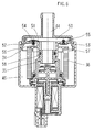
- valve 1 shows a section through an electrical switching valve 1, consisting of a coil housing 2, in which a coil body 3 with connections 4 and an armature yoke 5 are cast.
- a bearing section 7 for a magnet armature 8 and an armature core 9 are arranged in a central bore 6, the armature core 9 having a through opening 10.
- the valve 1 consists of a valve housing 11 with a valve seat 12 between two connecting pieces 13, 14, which cooperates with a valve plate 15.
- an intermediate rod 16 is clamped, which is guided radially in the valve housing 11 within longitudinal ribs 17 and protrudes through the through opening 10 of the armature core 9.
- the valve plate 15 is mounted radially and axially in a ball socket bearing 18, the intermediate rod 16 abutting the magnet armature 8 without radial bearing.
- a return spring 19 is arranged between the valve housing 11 and the intermediate rod 16, which loads the intermediate rod 16 against the magnet armature 8 and holds it in the basic position.
- the intermediate rod 16 has two disc collars 20 which cooperate with the longitudinal ribs 17 in the valve housing 11 and center the intermediate rod 16.
- Valve housing 11 and coil housing 2 each have frets 21 which are held together by sheet metal coils 22.
- Fig. 2 shows a variant of the embodiment according to Fig. 1, in which the valve housing 11 is inserted into a stepped bore 23 of a connection housing 24 and for each individual stepped bore 25, 26 has an O-ring 29, 30 inserted in a valve housing groove 27, 28 , wherein the valve housing 11 between the valve seat 12 and a step shoulder 31, which projects into the largest step bore 26, has openings 32 between the longitudinal ribs.
- the position of the electrical connections 4 is fixed by this measure.
- the other components correspond to the basic switching valve according to FIG. 1.
- FIG. 3 and 4 show a further variant in which the basic switching valve of the embodiment according to FIG. 2 is used and the connection housing is formed by a filter housing 33 which consists of a filter bell 34 which is pushed over a step 35 for the small step bore 25 and from a filter body 36, which is pushed as a tubular section over the step shoulder 31 for the large stepped bore 26, and from a tensioning housing 37 pushed over the coil housing 2, which is axially supported on the collar 21 of the coil housing 2 and with clip arms 38 in the filter bell 34 engages and snaps into recesses 39, wherein when snapped onto an axial wall 40, which is supported on the collar 21 of the bobbin case 2, radially shaped recesses 41 form spring segments 42 which are overpressed.
- the spring segments 42 are supported under spring action on the collar 21 of the bobbin case 2 when the filter bell 34 and bracing housing 37 are clipped, on which, on the other hand, the filter body 36 is supported, which with the other end face against an end wall 43 of the filter bell 34 abuts, the filter bell 34 having a connecting piece 44, which leads into the small stepped bore 25, and the radial recesses 41 form connection openings 45 to the atmosphere for a filter bell chamber 46 existing outside the filter body 36.
- FIG. 4 shows a view of FIG. 3 in the direction of the arrow, from which the recesses 41 or connection openings 45 and the spring segments 42 can be seen.
- a branch 47 is arranged on the connecting piece 44, 13 or connecting channel 25, on which the valve seat 12 is arranged, in which a suction or pressure valve 48 is arranged, the one Bypass channel 49 controls valve seat 12. 5 a suction valve is shown.
- FIG. 6 shows a switching valve according to the invention, which, based on the embodiment according to FIG. 5, has the special feature that the branch 44 is expanded to form an intermediate chamber 50 and in its axial boundary wall 51, which on the other hand delimits the chamber 46 existing outside the filter body 36,
- Two bypass channels 52, 53 are arranged, which are controlled by elastomer closing bodies 54, 55, which open or close when a predetermined pressure difference applied to them is exceeded, the axial boundary walls 51 being inserted by a funnel body 56 sealingly inserted into the filter bell 34 in front of the connecting piece channel 44 are formed, which supports the filter body 36 with a collar 57 and receives the step 35 with a central bore 58.
- FIG. 7 shows an embodiment in which the two bypass channels 52, 53 are arranged in a radial boundary wall 59, which is arranged between the intermediate chamber 50 and the filter bell chamber 46 existing outside the filter body 36, the radial boundary wall 59 being defined by an axial extension 60
- the step 35 is formed, which has a radial inner extension 61, which forms the intermediate chamber 50, and sealingly supports the filter body 36.
- bypass channels 52, 53 lead into the chamber existing within the filter body 36 and not into the chamber 46.
- the electrical switching valve according to the invention is suitable for a variety of uses in internal combustion engines, so that overall a high number of items can be expected. In the case of flexible production in particular, the embodiments according to the exemplary embodiments can be easily implemented.
- the valve is extremely simple and highly functional.
- valve bodies 54, 55 which are made of elastomer, can be obtained inexpensively as mass-produced articles, with the result that a reduction in price can be achieved by eliminating the usual springs.
Landscapes
- Engineering & Computer Science (AREA)
- General Engineering & Computer Science (AREA)
- Mechanical Engineering (AREA)
- Chemical & Material Sciences (AREA)
- Combustion & Propulsion (AREA)
- Life Sciences & Earth Sciences (AREA)
- Sustainable Development (AREA)
- Sustainable Energy (AREA)
- Transportation (AREA)
- Magnetically Actuated Valves (AREA)
- Multiple-Way Valves (AREA)
Abstract
Description
- Die Erfindung betrifft ein elektromagnetisches Schaltventil, insbesondere für eine Anwendung bei Brennkraftmaschinen, nach dem Oberbegriff des Anspruchs 1.
- Bei Brennkraftmaschinen werden Schaltventile für diverse Schaltfunktionen eingesetzt, zum Beispiel ist aus der DEA1 41 40 255 ein Schaltventil bei einer Entlüftungsvorrichtung für einen Brennstofftank einer Brennkraftmaschine bekannt, das eine Belüftungsleitung zur Atmosphäre steuert. Die absperrbare Belüftungsleitung ermöglicht es, gezielt Unter- und Überdrücke in der Anlage einstellen zu können, um dadurch deren Funktionstüchtigkeit zu überprüfen. Es handelt sich hierbei offenbar um ein Massenprodukt, das wirtschaftlich gefertigt werden muß.
- Eine wirtschaftliche Fertigung wird erreicht, wenn die Fertigungsanlagen eine hohe Auslastung haben, das heißt, eine große Fertigungsstückzahl vorliegt.
- Es ist daher Aufgabe der Erfindung, ausgehend von einem gattungsgemäßen Schaltventil dieses so auszubilden, daß es wirtschaftlich gefertigt und ausgehend von einem Basisschaltventil mehrere Anwendungen möglich werden können sowie so weiterzubilden, daß eine Bauraum- und Bauteileverringerung erreicht wird im Zusammenhang mit Maßnahmen zur Begrenzung der Unter- oder Überdrücke, die sonst die Anlage zerstören könnten.
- Diese Aufgabe ist durch die im Kennzeichen des Patentanspruchs 1 bzw. 10 angegebenen Merkmale gelöst worden. Vorteilhafte Weiterbildungen sind in den Unteransprüchen angegeben.
- Ausführungsbeispiele der Erfindung sind in der Zeichnung dargestellt und werden nachfolgend beschrieben.
- Diese zeigt:
- Fig. 1
ein erfindungsgemäßes elektrisches Schaltventil, - Fig. 2 und 3
alternative Ausbildungen des Schaltventils nach Fig. 1, - Fig. 4
eine Ansicht aus Fig. 3, - Fig. 5
eine besondere Ausbildung der Ausführung nach Fig. 3, - Fig. 6 und 7
alternative Ausführungen der vorliegenden Erfindung. - Fig. 1 zeigt einen Schnitt durch ein elektrisches Schaltventil 1, bestehend aus einem Spulengehäuse 2, in dem ein Spulenkörper 3 mit Anschlüssen 4 sowie ein Ankerjoch 5 vergossen sind. In einer zentralen Bohrung 6 sind ein Lagerabschnitt 7 für einen Magnetanker 8 sowie ein Ankerkern 9 angeordnet, wobei der Ankerkern 9 eine Durchgangsöffnung 10 aufweist. Desweiteren besteht das Ventil 1 aus einem Ventilgehäuse 11 mit einem Ventilsitz 12 zwischen zwei Anschlußstutzen 13, 14, der mit einer Ventilplatte 15 zusammenwirkt.
- Zwischen Magnetanker 8 und Ventilplatte 15 ist eine Zwischenstange 16 eingespannt, die im Ventilgehäuse 11 innerhalb von Längsrippen 17 radial geführt ist und durch die Durchgangsöffnung 10 des Ankerkerns 9 ragt. Die Ventilplatte 15 ist in einem Kugelpfannenlager 18 radial und axial gelagert, wobei die Zwischenstange 16 ohne radiale Lagerung am Magnetanker 8 anliegt.
- Zwischen dem Ventilgehäuse 11 und der Zwischenstange 16 ist eine Rückstellfeder 19 angeordnet, die die Zwischenstange 16 gegen den Magnetanker 8 belastet und diesen in Grundstellung hält. Die Zwischenstange 16 weist zwei Scheibenbünde 20 auf, die mit den Längsrippen 17 im Ventilgehäuse 11 zusammenwirken und die Zwischenstange 16 zentrieren. Ventilgehäuse 11 und Spulengehäuse 2 weisen jeweils Bünde 21 auf, die durch Blechumrollungen 22 zusammengehalten werden.
- Fig. 2 zeigt eine Variante der Ausführung nach Fig. 1, bei der das Ventilgehäuse 11 in eine Stufenbohrung 23 eines Anschlußgehäuses 24 eingesetzt ist und für jede einzelne Stufenbohrung 25, 26 einen in eine Ventilgehäusenut 27, 28 eingelegten O-Ring 29, 30 aufweist, wobei das Ventilgehäuse 11 zwischen dem Ventilsitz 12 und einem Stufenabsatz 31, der in die größte Stufenbohrung 26 hineinragt, zwischen den Längsrippen Durchbrüche 32 aufweist. Auf dem Stufenabsatz 31 kann eine Längsrippe bestehen, die in eine Ausnehmung der Stufenbohrung 26 hineinragt und das Schaltventil 1 gegen Verdrehen sichert. Durch diese Maßnahme ist die Lage der elektrischen Anschlüsse 4 fixiert.
Die weiteren Bauteile entsprechen dem Basisschaltventil nach Fig. 1. - Fig. 3 und 4 zeigen eine weitere Variante, bei der das Basisschaltventil der Ausführung nach Fig. 2 benutzt wird und das Anschlußgehäuse von einem Filtergehäuse 33 gebildet ist, das aus einer Filterglocke 34 besteht, die über einen Stufenabsatz 35 für die kleine Stufenbohrung 25 geschoben ist, und aus einem Filterkörper 36, der als Rohrabschnitt über den Stufenabsatz 31 für die große Stufenbohrung 26 geschoben ist, sowie aus einem über das Spulengehäuse 2 geschobene Verspanngehäuse 37, das sich an dem Bund 21 des Spulengehäuses 2 axial abstützt und mit Klippsarmen 38 in die Filterglocke 34 eingreift und in Ausnehmungen 39 einrastet, wobei beim Einrasten an einer Axialwand 40, die sich am Bund 21 des Spulengehäuses 2 abstützt, strahlenförmig ausgebildete Ausnehmungen 41 Federsegmente 42 bilden, die überdrückt werden.
- Wie in Fig. 3 ersichtlich, ist vorgesehen, daß sich die Federsegmente 42 bei verklippster Filterglocke 34 und Verspanngehäuse 37 unter Federwirkung an dem Bund 21 des Spulengehäuses 2 abstützen, an dem sich andererseits der Filterkörper 36 abstützt, der mit der anderen Stirnfläche gegen eine Stirnwand 43 der Filterglocke 34 anliegt, wobei die Filterglocke 34 einen Anschlußstutzen 44 aufweist, der in die kleine Stufenbohrung 25 führt, und die strahlenförmigen Ausnehmungen 41 Anschlußöffnungen 45 zur Atmosphäre für eine außerhalb des Filterkörpers 36 bestehende Filterglockenkammer 46 bilden.
- Fig. 4 zeigt eine Ansicht der Fig. 3 in Pfeilrichtung, aus der die Ausnehmungen 41 bzw. Anschlußöffnungen 45 sowie die Federsegmente 42 ersichtlich sind.
- In einer weiteren erfinderischen Ausführung nach Fig. 5 ist vorgesehen, daß an dem Anschlußstutzen 44, 13 oder Anschlußkanal 25, an dem der Ventilsitz 12 angeordnet ist, ein Abzweig 47 angeordnet ist, in dem ein Saug- oder Druckventil 48 angeordnet ist, das einen Bypasskanal 49 zum Ventilsitz 12 steuert. In der Fig. 5 ist ein Saugventil dargestellt.
- Fig. 6 zeigt ein erfindungsgemäßes Schaltventil, das ausgehend von der Ausführung nach Fig. 5 die Besonderheit aufweist, daß der Abzweig 44 zu einer Zwischenkammer 50 erweitert ist und in deren axialer Begrenzungswand 51, die andererseits die außerhalb des Filterkörpers 36 bestehende Kammer 46 abgrenzt, zwei Bypasskanäle 52, 53 angeordnet sind, die durch Elastomerschließkörper 54, 55 kontrolliert werden, die bei Überschreitung einer vorgegebenen, an ihnen anliegenden Druckdifferenz öffnen oder schließen, wobei die axialen Begrenzungswände 51 durch einen in die Filterglocke 34 vor dem Anschlußstutzenkanal 44 dichtend eingeschobenen Trichterkörper 56 gebildet sind, der mit einem Kragen 57 den Filterkörper 36 abstützt und mit einer zentralen Bohrung 58 den Stufenabsatz 35 aufnimmt.
- Fig. 7 zeigt eine Ausführung, bei der die zwei Bypasskanäle 52, 53 in einer radialen Begrenzungswand 59 angeordnet sind, die zwischen der Zwischenkammer 50 und der außerhalb des Filterkörpers 36 bestehende Filterglockenkammer 46 angeordnet ist, wobei die radiale Begrenzungswand 59 durch eine axiale Verlängerung 60 des Stufenabsatzes 35 gebildet ist, die eine radiale innere Erweiterung 61, die die Zwischenkammer 50 bildet, aufweist und den Filterkörper 36 dichtend lagert.
- Obwohl nicht extra dargestellt, kann eine andere Ausführungsform vorsehen, daß die Bypasskanäle 52, 53 in die innerhalb des Filterkörpers 36 bestehende Kammer und nicht in die Kammer 46 führen.
- Das erfindungsgemäße elektrische Schaltventil eignet sich für vielfältige Verwendungen bei Brennkraftmaschinen, so daß insgesamt mit einer hohen Fertigungsstückzahl gerechnet werden kann. Insbesondere bei einer flexiblen Fertigung lassen sich die Ausführungsformen gemäß den Ausführungsbeispielen leicht realisieren. Das Ventil weist eine große Einfachheit bei hoher Funktionssicherheit auf.
- Die Ausführungen nach Fig. 5, 6 und 7 lassen eine Verwendung des Schaltventils zu, bei der eine Druckbegrenzung innerhalb einer Anlage, zum Beispiel einer Entlüftungsvorrichtung für einen Brennstofftank einer Brennkraftmaschine, notwendig ist, um bei Störungen in der Druckbeschaltung größeren Schaden zu verhindern, der durch zu hohe Unter- oder Überdrücke entstehen kann. In diesem Fall würde über das Saug- oder Druckventil ein Druckausgleich erfolgen und dadurch ein vorgegebener zulässiger Druck nicht über- oder unterschritten werden.
- Die erfindungsgemäßen Ausführungen lassen sich mit geringem Bauaufwand realisieren. Die aus Elastomer bestehenden Ventilkörper 54, 55 sind als Massenartikel preiswert zu beziehen, womit insgesamt auch durch den Wegfall von bisher üblichen Federn eine Verbilligung erreichbar wird.
Claims (12)
- Elektromagnetisches Schaltventil, insbesondere für die Verwendung bei einer Brennkraftmaschine, bestehend aus einem Spulengehäuse mit Ventilplatte, dadurch gekennzeichnet, daß zwischen Magnetanker (8) und Ventilplatte (15) eine Zwischenstange (16) eingespannt ist, die im Ventilgehäuse (11) innerhalb von Längsrippen (17) radial geführt ist und die Ventilplatte (15) in einem Kugelpfannenlager (18) radial und axial lagert, wobei die Zwischenstange (16) ohne radiale Lagerung am Magnetanker (8) anliegt.
- Schaltventil nach Anspruch 1, dadurch gekennzeichnet, daß zwischen Ventilgehäuse (11) und Zwischenstange (16) eine Rückstellfeder (19) angeordnet ist.
- Schaltventil nach Anspruch 1 oder 2, dadurch gekennzeichnet, daß die Zwischenstange (16) zwei Scheibenbünde (20) aufweist, die mit den Längsrippen (17) zusammenwirken.
- Schaltventil nach einem der vorstehenden Ansprüche, dadurch gekennzeichnet, daß das Ventilgehäuse (11) stromauf und stromab eines Ventilsitzes (12) Anschlußstutzen (13, 14) für das zu schaltende Medium aufweist.
- Schaltventil nach einem der Ansprüche 1 bis 3, dadurch gekennzeichnet, daß das Ventilgehäuse (11) in eine Stufenbohrung (23) eines Anschlußgehäuses (24) eingesetzt ist und für jede Stufenbohrung (25, 26) einen in eine Ventilgehäusenut (27, 28) eingelegten O-Ring (29, 30) aufweist, wobei das Ventilgehäuse (11) zwischen dem Ventilsitz (12) und dem Stufenabsatz (31), der in die größte Stufenbohrung (26) hineinragt, zwischen den Längsrippen (17) Durchbrüche (32) aufweist.
- Schaltventil nach Anspruch 5, dadurch gekennzeichnet, daß das Anschlußgehäuse von einem Filtergehäuse (33) gebildet ist, das aus einer Filterglocke (34) besteht, die über den Stufenabsatz (35) für die kleine Stufenbohrung (25) geschoben ist, und aus einem Filterkörper (36), der als Rohrabschnitt über den Stufenabsatz (31) für die große Stufenbohrung (26) geschoben ist, sowie aus einem über das Spulengehäuse (2) geschobenen Verspanngehäuse (37), das sich an einem Bund (21) axial abstützt und mit Klippsarmen (38) in die Filterglocke (34) eingreift und in Ausnehmungen (39) einrastet, wobei beim Einrasten an der Axialwand (40), die sich am Bund (21) abstützt, strahlenförmig ausgebildete Ausnehmungen (41) Federsegmente (42) bilden, die überbrückt werden.
- Schaltventil nach Anspruch 6, dadurch gekennzeichnet, daß sich die Federsegmente (42) bei verklippster Filterglocke (34) und verklippstem Verspanngehäuse (37) unter Federwirkung an dem Bund (21) abstützen, an dem sich andererseits der Filterkörper (36) abstützt, der mit der anderen Stirnfläche gegen eine Stirnwand (43) der Filterglocke (34) anliegt.
- Schaltventil nach einem der Ansprüche 6 oder 7, dadurch gekennzeichnet, daß die Filterglocke (34) einen Anschlußstutzen (44) aufweist, der in die kleine Stufenbohrung (25) führt, wobei die strahlenförmigen Ausnehmungen (41) Anschlußöffnungen (45) zur Atmosphäre für eine außerhalb des Filterkörpers (36) bestehende Filterglockenkammer (46) bilden.
- Elektromagnetisches Schaltventil nach dem Oberbegriff des Anspruchs 1, dadurch gekennzeichnet, daß der Anschlußstutzen (13) oder die Anschlußbohrung (25), an dem der Ventilsitz (12) angeordnet ist, einen Abzweig (47) aufweist, in dem ein Saug- und/oder Druckventil (48) angeordnet ist, das einen Bypasskanal (49) zum Ventilsitz (12) steuert.
- Schaltventil nach Anspruch 9, dadurch gekennzeichnet, daß der Abzweig (47) zu einer Zwischenkammer (50) erweitert ist und in deren radialer oder axialer Begrenzungswand (51), die andererseits eine vor dem Ventilsitz (12) liegende, außerhalb des Filterkörpers (36) bestehende Filterglockenkammer (46) oder innerhalb des Filterkörpers bestehende Kammer abgrenzt, zwei Bypasskanäle (52, 53) angeordnet sind, die durch Elastomerschließkörper (54, 55) kontrolliert werden, die bei Überschreitung einer vorgegebenen, an ihnen anliegenden Druckdifferenz öffnen oder schließen.
- Schaltventil nach Anspruch 10, dadurch gekennzeichnet, daß die axialen Begrenzungswände (51) durch einen in die Filterglocke (34) vor den Anschlußstutzenkanal (44) dichtend eingeschobenen Trichterkörper (56) gebildet sind, der mit einem Kragen (57) den Filterkörper (36) abstützt und mit einer zentralen Bohrung (58) den Stufenabsatz (35) aufnimmt.
- Schaltventil nach Anspruch 11, dadurch gekennzeichnet, daß die radiale Begrenzungswand (59) durch eine axiale Verlängerung (60) des Stufenabsatzes (35) gebildet ist, die eine radiale innere Erweiterung (61) aufweist und den Filterkörper (36) dichtend lagert.
Applications Claiming Priority (2)
| Application Number | Priority Date | Filing Date | Title |
|---|---|---|---|
| DE4430723 | 1994-08-30 | ||
| DE19944430723 DE4430723A1 (de) | 1994-03-17 | 1994-08-30 | Elektromagnetisches Schaltventil |
Publications (2)
| Publication Number | Publication Date |
|---|---|
| EP0699859A1 true EP0699859A1 (de) | 1996-03-06 |
| EP0699859B1 EP0699859B1 (de) | 1998-04-08 |
Family
ID=6526894
Family Applications (1)
| Application Number | Title | Priority Date | Filing Date |
|---|---|---|---|
| EP95111122A Expired - Lifetime EP0699859B1 (de) | 1994-08-30 | 1995-07-15 | Elektromagnetisches Schaltventil |
Country Status (6)
| Country | Link |
|---|---|
| US (1) | US5676345A (de) |
| EP (1) | EP0699859B1 (de) |
| JP (1) | JPH0875027A (de) |
| KR (1) | KR960008143A (de) |
| DE (1) | DE59501830D1 (de) |
| ES (1) | ES2114252T3 (de) |
Cited By (2)
| Publication number | Priority date | Publication date | Assignee | Title |
|---|---|---|---|---|
| WO1997016640A1 (de) * | 1995-10-27 | 1997-05-09 | Robert Bosch Gmbh | Ventil zum dosierten einleiten von aus einem brennstofftank einer brennkraftmaschine verflüchtigtem brennstoffdampf |
| WO2000077427A3 (en) * | 1999-06-14 | 2001-04-19 | Siemens Canada Ltd | Canister purge valve for high regeneration airflow |
Families Citing this family (10)
| Publication number | Priority date | Publication date | Assignee | Title |
|---|---|---|---|---|
| US6109302A (en) * | 1999-04-23 | 2000-08-29 | Delphi Technologies, Inc. | Three-way gas management valve |
| US6213447B1 (en) * | 1999-07-29 | 2001-04-10 | Delphi Technologies, Inc. | Poppet value having a compliant shaft guide and compliant valve head |
| DE10107618A1 (de) * | 2001-02-17 | 2002-08-29 | Pierburg Ag | Ventilanordnung zur Druckregelung der Kraftstoffzufuhr bei einer Brennkraftmaschine |
| DE10234609A1 (de) * | 2002-07-30 | 2004-02-19 | Robert Bosch Gmbh | Ventil zur Regelung eines strömenden Mediums, insbesondere Wasserventil |
| US20040036048A1 (en) * | 2002-08-20 | 2004-02-26 | Petersen Peter Waygaard | Gaseous fuel injector |
| DE10255740A1 (de) | 2002-11-28 | 2004-06-09 | Bosch Rexroth Ag | Direktgesteuertes prop. Druckbegrenzungsventil |
| US8430378B2 (en) * | 2008-05-30 | 2013-04-30 | South Bend Controls Holdings Llc | High flow proportional valve |
| DE102008056247B4 (de) * | 2008-11-06 | 2010-09-09 | Itw Automotive Products Gmbh | Thermostatventilanordnung und Kühlsystem für ein Kraftfahrzeug |
| DE102013220740A1 (de) * | 2013-10-14 | 2015-04-16 | Continental Automotive Gmbh | Ventil |
| EP4288298A1 (de) * | 2021-02-05 | 2023-12-13 | Donaldson Company, Inc. | Entlüfter für hydrauliktank |
Citations (5)
| Publication number | Priority date | Publication date | Assignee | Title |
|---|---|---|---|---|
| US2596409A (en) * | 1947-03-14 | 1952-05-13 | A P Controls Corp | Solenoid gas valve |
| US3810489A (en) * | 1973-02-05 | 1974-05-14 | Gen Motors Corp | Solenoid latched diaphragm fuel shut-off valve assembly |
| DE4033946A1 (de) * | 1990-10-25 | 1992-04-30 | Rausch & Pausch | Hydraulisches 2/2 magnetventil |
| US5145148A (en) * | 1991-11-14 | 1992-09-08 | Siemens Automotive L.P. | Solenoid valve operating mechanism comprising a pin having a plastic sleeve molded onto a metal core |
| DE4305987C1 (de) * | 1993-02-26 | 1993-11-25 | Honeywell Bv | Magnetventil mit Schmutzfalle |
Family Cites Families (4)
| Publication number | Priority date | Publication date | Assignee | Title |
|---|---|---|---|---|
| US2703582A (en) * | 1949-12-16 | 1955-03-08 | Stepanian John | Burner control valve responsive to change in the position of the burner |
| US3554487A (en) * | 1969-06-16 | 1971-01-12 | Int Controls Corp | Rotary valve with pivotable seat |
| DE3431037A1 (de) * | 1984-08-23 | 1986-03-06 | Leybold-Heraeus GmbH, 5000 Köln | Magnetventil fuer die vakuumanwendung |
| DE4140255C3 (de) * | 1991-12-06 | 1999-05-20 | Bosch Gmbh Robert | Entlüftungsvorrichtung für einen Brennstofftank einer Brennkraftmaschine |
-
1995
- 1995-07-15 DE DE59501830T patent/DE59501830D1/de not_active Expired - Fee Related
- 1995-07-15 EP EP95111122A patent/EP0699859B1/de not_active Expired - Lifetime
- 1995-07-15 ES ES95111122T patent/ES2114252T3/es not_active Expired - Lifetime
- 1995-08-21 KR KR1019950025604A patent/KR960008143A/ko not_active Application Discontinuation
- 1995-08-29 JP JP7220696A patent/JPH0875027A/ja active Pending
- 1995-08-30 US US08/521,592 patent/US5676345A/en not_active Expired - Fee Related
Patent Citations (5)
| Publication number | Priority date | Publication date | Assignee | Title |
|---|---|---|---|---|
| US2596409A (en) * | 1947-03-14 | 1952-05-13 | A P Controls Corp | Solenoid gas valve |
| US3810489A (en) * | 1973-02-05 | 1974-05-14 | Gen Motors Corp | Solenoid latched diaphragm fuel shut-off valve assembly |
| DE4033946A1 (de) * | 1990-10-25 | 1992-04-30 | Rausch & Pausch | Hydraulisches 2/2 magnetventil |
| US5145148A (en) * | 1991-11-14 | 1992-09-08 | Siemens Automotive L.P. | Solenoid valve operating mechanism comprising a pin having a plastic sleeve molded onto a metal core |
| DE4305987C1 (de) * | 1993-02-26 | 1993-11-25 | Honeywell Bv | Magnetventil mit Schmutzfalle |
Cited By (2)
| Publication number | Priority date | Publication date | Assignee | Title |
|---|---|---|---|---|
| WO1997016640A1 (de) * | 1995-10-27 | 1997-05-09 | Robert Bosch Gmbh | Ventil zum dosierten einleiten von aus einem brennstofftank einer brennkraftmaschine verflüchtigtem brennstoffdampf |
| WO2000077427A3 (en) * | 1999-06-14 | 2001-04-19 | Siemens Canada Ltd | Canister purge valve for high regeneration airflow |
Also Published As
| Publication number | Publication date |
|---|---|
| US5676345A (en) | 1997-10-14 |
| JPH0875027A (ja) | 1996-03-19 |
| DE59501830D1 (de) | 1998-05-14 |
| EP0699859B1 (de) | 1998-04-08 |
| KR960008143A (ko) | 1996-03-22 |
| ES2114252T3 (es) | 1998-05-16 |
Similar Documents
| Publication | Publication Date | Title |
|---|---|---|
| EP1285188B1 (de) | Ventil mit elastischen dichtelementen | |
| EP0699859B1 (de) | Elektromagnetisches Schaltventil | |
| DE4012832C2 (de) | Magnetventil | |
| EP0864794A2 (de) | Proportional-Drosselventil | |
| EP2052145B1 (de) | Schwingungs- und pulsationsgedämpfter elektropneumatischer wandler | |
| DE19649554A1 (de) | Membrandruckregelventilanordnung | |
| DE102016204569A1 (de) | Gas-Direkteinspritzdüse mit reduzierter Leckage | |
| DE10046939B4 (de) | Tauchankersystem mit Anschlagdämpfung | |
| DE10118162C2 (de) | Brennstoffeinspritzventil | |
| DE102010009400A1 (de) | Elektromagnetisches Hydraulikventil | |
| DE4419875B4 (de) | Elektromagnetisches Umschaltventil | |
| DE4439695C2 (de) | Magnetventil und dessen Verwendung | |
| DE4409033C2 (de) | Elektromagnetisches Schaltventil | |
| WO2004109089A1 (de) | Tankentlüftungsventil | |
| DE3344816A1 (de) | Expansionsventil | |
| DE19861176B4 (de) | Stellteil | |
| EP0806595A1 (de) | Elektromagnetisches Schaltventil | |
| DE19740580C2 (de) | Elektromagnetisches Schaltventil | |
| DE102010030429A1 (de) | Injektor, insbesondere Common-Rail-Injektor | |
| DE102010044442A1 (de) | Elektromagnet-Ventilvorrichtung mit zwei Arbeitsanschlüssen | |
| DE3336469C2 (de) | ||
| DE112017005229T5 (de) | Magnetventilbaugruppe mit Vorsteuerdrucksteuerung | |
| DE2003739A1 (de) | Ventil mit einer einen Ventilkoerper aufnehmenden Ventilkammer | |
| DE19908440A1 (de) | Wegesitzventil | |
| DE10118161B9 (de) | Brennstoffeinspritzventil |
Legal Events
| Date | Code | Title | Description |
|---|---|---|---|
| PUAI | Public reference made under article 153(3) epc to a published international application that has entered the european phase |
Free format text: ORIGINAL CODE: 0009012 |
|
| AK | Designated contracting states |
Kind code of ref document: A1 Designated state(s): DE ES FR GB IT |
|
| 17P | Request for examination filed |
Effective date: 19960323 |
|
| RAP1 | Party data changed (applicant data changed or rights of an application transferred) |
Owner name: PIERBURG AKTIENGESELLSCHAFT |
|
| 17Q | First examination report despatched |
Effective date: 19970609 |
|
| GRAG | Despatch of communication of intention to grant |
Free format text: ORIGINAL CODE: EPIDOS AGRA |
|
| GRAG | Despatch of communication of intention to grant |
Free format text: ORIGINAL CODE: EPIDOS AGRA |
|
| GRAH | Despatch of communication of intention to grant a patent |
Free format text: ORIGINAL CODE: EPIDOS IGRA |
|
| GRAH | Despatch of communication of intention to grant a patent |
Free format text: ORIGINAL CODE: EPIDOS IGRA |
|
| GRAA | (expected) grant |
Free format text: ORIGINAL CODE: 0009210 |
|
| ITF | It: translation for a ep patent filed | ||
| AK | Designated contracting states |
Kind code of ref document: B1 Designated state(s): DE ES FR GB IT |
|
| REF | Corresponds to: |
Ref document number: 59501830 Country of ref document: DE Date of ref document: 19980514 |
|
| REG | Reference to a national code |
Ref country code: ES Ref legal event code: FG2A Ref document number: 2114252 Country of ref document: ES Kind code of ref document: T3 |
|
| GBT | Gb: translation of ep patent filed (gb section 77(6)(a)/1977) |
Effective date: 19980515 |
|
| ET | Fr: translation filed | ||
| PLBE | No opposition filed within time limit |
Free format text: ORIGINAL CODE: 0009261 |
|
| STAA | Information on the status of an ep patent application or granted ep patent |
Free format text: STATUS: NO OPPOSITION FILED WITHIN TIME LIMIT |
|
| 26N | No opposition filed | ||
| PGFP | Annual fee paid to national office [announced via postgrant information from national office to epo] |
Ref country code: GB Payment date: 20010614 Year of fee payment: 7 |
|
| PGFP | Annual fee paid to national office [announced via postgrant information from national office to epo] |
Ref country code: FR Payment date: 20010709 Year of fee payment: 7 |
|
| PGFP | Annual fee paid to national office [announced via postgrant information from national office to epo] |
Ref country code: DE Payment date: 20010713 Year of fee payment: 7 |
|
| PGFP | Annual fee paid to national office [announced via postgrant information from national office to epo] |
Ref country code: ES Payment date: 20010716 Year of fee payment: 7 |
|
| REG | Reference to a national code |
Ref country code: GB Ref legal event code: IF02 |
|
| PG25 | Lapsed in a contracting state [announced via postgrant information from national office to epo] |
Ref country code: GB Free format text: LAPSE BECAUSE OF NON-PAYMENT OF DUE FEES Effective date: 20020715 |
|
| PG25 | Lapsed in a contracting state [announced via postgrant information from national office to epo] |
Ref country code: ES Free format text: LAPSE BECAUSE OF NON-PAYMENT OF DUE FEES Effective date: 20020716 |
|
| PG25 | Lapsed in a contracting state [announced via postgrant information from national office to epo] |
Ref country code: DE Free format text: LAPSE BECAUSE OF NON-PAYMENT OF DUE FEES Effective date: 20030201 |
|
| GBPC | Gb: european patent ceased through non-payment of renewal fee |
Effective date: 20020715 |
|
| PG25 | Lapsed in a contracting state [announced via postgrant information from national office to epo] |
Ref country code: FR Free format text: LAPSE BECAUSE OF NON-PAYMENT OF DUE FEES Effective date: 20030331 |
|
| REG | Reference to a national code |
Ref country code: FR Ref legal event code: ST |
|
| REG | Reference to a national code |
Ref country code: ES Ref legal event code: FD2A Effective date: 20030811 |
|
| PG25 | Lapsed in a contracting state [announced via postgrant information from national office to epo] |
Ref country code: IT Free format text: LAPSE BECAUSE OF NON-PAYMENT OF DUE FEES Effective date: 20050715 |