EP0699490A1 - Dispositif de commande, en particulier pour machines de formage - Google Patents
Dispositif de commande, en particulier pour machines de formage Download PDFInfo
- Publication number
- EP0699490A1 EP0699490A1 EP95112263A EP95112263A EP0699490A1 EP 0699490 A1 EP0699490 A1 EP 0699490A1 EP 95112263 A EP95112263 A EP 95112263A EP 95112263 A EP95112263 A EP 95112263A EP 0699490 A1 EP0699490 A1 EP 0699490A1
- Authority
- EP
- European Patent Office
- Prior art keywords
- sensing element
- workpiece
- receiving part
- displacement sensor
- evaluation circuit
- Prior art date
- Legal status (The legal status is an assumption and is not a legal conclusion. Google has not performed a legal analysis and makes no representation as to the accuracy of the status listed.)
- Granted
Links
Images

Classifications
-
- B—PERFORMING OPERATIONS; TRANSPORTING
- B21—MECHANICAL METAL-WORKING WITHOUT ESSENTIALLY REMOVING MATERIAL; PUNCHING METAL
- B21J—FORGING; HAMMERING; PRESSING METAL; RIVETING; FORGE FURNACES
- B21J15/00—Riveting
- B21J15/10—Riveting machines
- B21J15/28—Control devices specially adapted to riveting machines not restricted to one of the preceding subgroups
- B21J15/285—Control devices specially adapted to riveting machines not restricted to one of the preceding subgroups for controlling the rivet upset cycle
-
- B—PERFORMING OPERATIONS; TRANSPORTING
- B21—MECHANICAL METAL-WORKING WITHOUT ESSENTIALLY REMOVING MATERIAL; PUNCHING METAL
- B21J—FORGING; HAMMERING; PRESSING METAL; RIVETING; FORGE FURNACES
- B21J15/00—Riveting
- B21J15/10—Riveting machines
- B21J15/12—Riveting machines with tools or tool parts having a movement additional to the feed movement, e.g. spin
Definitions
- the invention relates to a device for checking at least one receiving part and a workpiece which is partially received by the latter and can be connected to the receiving part by material deformation, the workpiece projecting beyond a top side of the receiving part by a certain protrusion dimension.
- a device for checking at least one receiving part and a workpiece which is partially received by the latter and can be connected to the receiving part by material deformation, the workpiece projecting beyond a top side of the receiving part by a certain protrusion dimension.
- Such a device is intended in particular for mechanical mechanical material deformation.
- the invention is based on the object of specifying a device of the type mentioned at the beginning with which improved quality assurance can be achieved with regard to the parts to be connected to one another by material deformation.
- the workpiece to be deformed and the at least one receiving part which receives the workpiece to be deformed or which is penetrated by the workpiece to be deformed are detected by means of separate sensing elements.
- a first sensing element moves from an initial position towards the receiving part in order to contact the receiving part after covering a first distance. At this moment the further advance of the first sensing element is prevented.
- the driving force with which the first sensing element is moved forward is far from sufficient to deform or damage the first receiving part when making contact.
- the workpiece to be deformed is scanned by means of a second sensing element.
- the second probe organ likewise moves from an initial position towards the workpiece in order to contact it after covering a second distance.
- both probes it also applies to the driving force with which the second probe element is moved forward that there is no deformation or damage to the workpiece during contacting.
- the relative position of both Sensing organs determined. With knowledge of the starting positions of both sensing elements and by measuring the distances covered by both sensing elements, the path difference between the covered distances of the two sensing elements can be determined.
- the path difference determined in this way is compared with the protrusion dimension in order for the workpiece to be deformed to protrude beyond the at least one receiving part or, in the case of several receiving parts, beyond the uppermost receiving part closest to the sensing elements; because with the two sensing elements the top of the arrangement of the workpiece to be deformed and the receiving part or receiving parts facing the two sensing elements has just been approached.
- the path difference determined thus represents the actual protrusion dimension. If the path difference is compared with the predetermined (target) protrusion dimension, a tolerance range can be used to decide whether the actual protrusion dimension deviates from the target protrusion dimension by more than the tolerance range.
- both the presence of the workpiece to be deformed (for example rivet) and the presence of the at least one receiving part can be detected, a statement being made according to the invention is whether the detected parts are those which, viewed in relation to one another (taking tolerances into account), have desired dimensions in the direction of movement of the sensing elements.
- the path difference can be determined by measuring the distances covered by the two sensing elements, starting from their starting positions until they come to a standstill, and then determining the difference between the distances covered, for which purpose the relative position of their starting positions must be known.
- An alternative procedure for determining the path difference is to measure only the path by which the two sensing elements have moved in comparison to their starting positions until they stand still. If, for example, the distance between the two sensing elements in the direction of their movement is known (relative position of their starting positions), the path difference can be measured directly by a distance measuring device which measures the relative movement of the one sensing element to the other sensing element.
- the leading (first) touch element which contacts first when the workpiece and the receiving part are present, is resiliently mounted in the direction of the receiving part and workpiece on the second touch element and / or on a holding element holding it, and that the second touch element is driven . If the first sensing element then comes into contact with the receiving part, it is moved back in relation to the further advancing first sensing element, which has not yet reached the workpiece. This distance is then measured by the displacement sensor. Taking into account the relative position of the starting positions of the two sensing elements (distance between them in the direction of movement in the starting position) and the return movement of the first sensing element relative to the second, the actual overhang dimension of the workpiece can then be determined via the receiving part.
- the standstill of a sensing element is expediently determined by the fact that the output signal of a displacement sensor measuring the forward movement of the relevant sensing element no longer changes.
- the standstill of a sensing element can also be determined by measuring mechanical stresses of the machine frame that holds the sensing elements and is displaceably supported. If a probe element moved forward with a certain force strikes the part to be contacted by it (workpiece or receiving part), the drive force leads to detectable mechanical stresses in the overall construction. If the measured mechanical tension exceeds a threshold value, this indicates that the probe element concerned has touched down. A separate detector for measuring mechanical stresses must be provided for each probe, if both probes are driven in the direction of the workpiece and the receiving part.
- one detector is sufficient to determine mechanical stresses if the distance by which the spring-mounted feeler leads the other viewed in the direction of movement is greater is the expected projection of the workpiece relative to the receiving part.
- the very decisive advantage of the device according to the invention is that the invention can be implemented directly in a deformation machine, for example a riveting machine. Doing so the deformation or riveting tool the function of the (second) sensing element for detecting the workpiece or rivet to be deformed. The other (first) feeler element is then mounted on the rivet head carrying the riveting tool so as to be displaceable relative to it. The contact surface of the first sensing element leads the side with which the riveting tool strikes the rivet by more than the expected overhang dimension.
- the actual deformation of the rivet takes place, in particular, when the riveting tool is moving, this either performing a wobbling movement (wobble riveting method) or moving along a trochoid, in particular a hypotrochoid (radial riveting method).
- the feed force with which the riveting tool is advanced until it rests on the rivet can be equal to the pressing force with which the moving riveting tool is pressed against the rivet.
- the riveting tool can also be moved forward with less force until it touches the rivet.
- the invention is also applicable in this case.
- each travel sensor measures the total distance covered by the sensing element assigned to it. If you know the starting position, you can use the Way the extent of the part (workpiece or receiving part) contacted by the relevant sensing element in the direction of movement of the sensing elements can be determined.
- error signals are then output in the event that the workpiece or the receiving part or parts has an extension outside the tolerances in the direction of movement of the sensing elements.
- one displacement sensor can also be used to determine the total distance of a sensing element and the other displacement sensor can be used to determine the relative displacement of the two sensing elements.
- the starting position of the one sensing element, the total path of which is measured, and the offset of the two sensing elements in the direction of movement and in the starting position of both sensing elements are known.
- the extent of the part contacted by it can be determined, while taking into account the relative distance covered by both sensing elements at standstill and the measured distance, the extent of the other part (receiving part or workpiece ) can be determined in the direction of movement of the sensing elements.
- the probe element scanning the workpiece expediently remains in contact with the workpiece even during the mechanical deformation of the workpiece. From the beginning of the mechanical deformation, the additional distance is then measured, which continues with a certain pressing force on the workpiece rests second sensing element due to the compression of the workpiece in the direction of movement of the sensing elements. If a specified target additional travel distance is reached before the expiry of a likewise specified minimum time period or until a maximum time period which is greater than the minimum time period has expired, an error message is output.
- This error display means that the material of the workpiece to be deformed is too soft (covering the additional travel distance before a minimum time - minimum time period) or too hard (even if a maximum time period has elapsed, the target additional travel distance has not been covered by the second probe). With this check, statements can be made about the quality of the material of the workpiece.
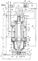
- the riveting machine 10 has a support frame 12 or a frame which has a support surface 14 and a vertical support arm 16 which is connected to the support surface 14 and projects upwards at right angles therefrom.
- a machine housing 18 is attached to the support arm 16.
- a pneumatic piston 20 is slidably mounted in the machine housing 18.
- the piston 20 is axially movable parallel to the extension of the support arm 16 at right angles in the direction of the support surface 14 and vice versa.
- the piston 20 has a radially outwardly projecting flange 22 which moves in a cavity 24 of the machine housing 18 when the piston 20 is moved.
- the cavity 24 is connected to a pneumatic pressure line 26 and a pneumatic vent line 28. When compressed air is supplied via the pressure line 26, the piston 20 is against the Force moved by a spring (not shown) in the direction of the bearing surface 14.
- the piston 20 is hollow and has at its axial ends internal pivot bearings 30, 32 for a drive shaft 34 which can be driven in rotation.
- the drive shaft 34 which extends axially through the piston 20, carries a tool holder or rivet head 36, which holds a riveting tool 38 (striker), on its lower, protruding end facing the bearing surface 14.
- the striker is held clamped on the lower end of the tool holder 36 facing away from the drive shaft 34.
- the end 40 of the drive shaft 34 which projects upward beyond the piston 20 is designed as a polygonal profile and is received by a sleeve 42 of the same cross section.
- the upper end 40 is slidably received by the sleeve 42.
- the sleeve 42 is rotatably supported and driven by an electric motor indicated at 34.
- the electric motor 44 When the electric motor 44 is actuated, it drives the sleeve 42. This rotates the tool holder 36 and with it the riveting tool 38. A deformation when the riveting tool 38 is rotating is brought about by moving the piston 20 in the direction of the bearing surface 14.
- the axial length of the sleeve 42 and the drive shaft end 40 is dimensioned such that the sleeve 42 and drive shaft 34 are still in engagement with one another even in the most disengaged lowest position of the piston 20.
- the riveting machine 10 described here is a wobble or a radial riveting machine in which the cold deformation of a workpiece to be deformed by applying a pressing force with which the riveting tool 38 presses against the one to be deformed Workpiece presses, and simultaneous wobble or rotary movement of the riveting tool 38 takes place.
- a receptacle is shown at 46, which rests on the support surface 14 and is fixed there.
- the receptacle 46 in turn carries the parts to be riveted together.
- the workpiece to be deformed is a threaded stud 48 which has a tapered bolt end 50 opposite the riveting tool 38 and a threaded section 54 which carries an internally threaded bore 52.
- the tapered section 50 extends through an opening in a receiving part 56 indicated at 56.
- the part of the tapered threaded bolt section 50 (protrusion) projecting from the tool holder 36 or the riveting tool 38 is deformed by cold deformation by means of the riveting tool to form the so-called closing head, which extends radially over the
- the opening in the receiving part 56 protrudes and projects radially beyond it.
- the upper side 58, facing the tool holder 36 and the riveting tool 38, of the arrangement to be riveted from the threaded stud bolt 48 and the receiving part 56 has the projection 60 required for the material deformation.
- a receiving part 56 in the form of a plate
- the threaded stud 48 workpiece
- the rivet connection ensures that the threaded stud 48 is held on the receiving part 56, which is, for example, a plate.
- rivets are used to connect several parts together.
- a rivet would be, for example, two plate-shaped ones Connect the receiving parts to one another, the head of the rivet abutting the one receiving part and the rivet shaft extending through openings that are aligned with one another in both or the plurality of receiving parts.
- a rivet tool 38 which collects the tool holder 36, is arranged at a distance radially surrounding probe sleeve 62.
- the sensing sleeve 62 is captively received in an annular groove 64 of the piston 20.
- the annular groove 64 is arranged at the lower end of the piston 20 offset radially outwards.
- the piston 20 is arranged outside the machine housing 18.
- the sensing sleeve 62 extends in the axial extension of the piston 20 beyond the riveting tool 38.
- the sensing sleeve 62 tapers and has an annular end face 66.
- a helical compression spring 72 is arranged between the end 68 of the sensing sleeve 62 immersed in the annular groove 64 and the base 70 of the annular groove 64. This helical compression spring 72 biases the sensing sleeve 62 in the direction of the bearing surface 14 of the support frame 12.
- the annular end face 66 of the sensing sleeve 62 protrudes beyond the end face 74 of the riveting tool 38.
- the axial distance a between these two surfaces ie the distance between these two surfaces in the direction of movement of the piston 20, is greater than the (actual) projection b by which the tapered distance 50 of the threaded stud 48 projects beyond the top 58 of the receiving part 56.
- the riveting machine 10 is also provided with a displacement sensor 76, which measures the displacement of the piston 20 relative to the machine housing 18.
- the extent to which the sensing sleeve 62 can move relative to the piston 20 against the force of the helical compression spring 72 is determined by means of a measuring device 78 by means of a displacement sensor.
- the machine 10 also has a detector 80 in the form of a strain gauge for measuring mechanical stresses of the support frame 12. The function of this detector 80 will be discussed further below.
- the two displacement sensors 76 and 78 and the detector 80 are connected to an evaluation circuit 82 which receives the output signals of the displacement sensors and the detector.
- the evaluation circuit 82 is also electrically connected to the motor 44 in order to control it, in particular to switch it on and off.
- a display / data input device 84 is also connected to the evaluation circuit 82 and has a display part 86 and a keypad 88 for data input.
- the evaluation circuit 82 is connected to control valves 90, 92 for the pressure line 26 and the vent line 28 in order to enable or block these lines.
- the riveting machine 10 With the riveting machine 10 described here, it can be checked in the phase immediately before the cold-forming process whether the parts to be riveted together are located on the support surface 14 or in the receptacle 46 of the support surface 14, whether the (actual) projection b taking into account Tolerances corresponds to a predetermined target value and whether the parts to be riveted have the required target dimensions.
- the riveting machine 10 operates as follows to check all these specifications.
- the control valves 90 and 92 are opened by corresponding output signals of the evaluation circuit 82, with the result that the piston 20 is moved towards the bearing surface 14 in the direction of the arrow 94.
- the riveting tool 38 consequently also moves with the piston 20 in the direction of the threaded stud bolt 48 and the sensing sleeve 62 in the direction of the support part 56. The riveting tool 38 stands still during this phase of the advance movement.
- the advancement of the piston 20 comes to an end at the moment in which the end face 74 touches the threaded stud 48.
- This touchdown is recognized in the evaluation circuit 82.
- the detector 80 arranged between the machine housing 18 and the support arm 16 measures this increasing mechanical tension.
- the evaluation signal 82 of the detector 80 is compared with a threshold value in the evaluation circuit 82. If the output signal of the detector 80 exceeds the threshold value, the evaluation circuit 82 interprets this as placing the riveting tool 38 on the threaded stud bolt 48.
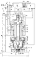
- the riveting machine 10 is in the situation shown in the drawing in FIG. 3. Both the annular end face 66 of the sensing sleeve 62 and the end face 74 of the riveting tool 38 rest on the receiving part 56 or the threaded stud 48.
- the displacement sensor 78 the output signal of which is fed to the evaluation circuit 82, can now be used to determine the amount by which the sensing sleeve 62 has moved relative to the piston 20, starting from the starting position. Since the distance a between the two surfaces 66 and 74 in the starting position is known and the displacement of the sensing sleeve 62 relative to the piston 20 is measured, the distance between the surfaces 66 and 74 can now be determined.
- This distance corresponds exactly to the actual overhang b (see FIG. 3).
- a target overhang which was previously entered into the evaluation circuit 82 via the keypad 88
- the statement can thus be made as to whether the actual overhang b is within the predetermined tolerance. If this is not the case, the evaluation circuit generates an error signal indicating this state, which generates a corresponding optical display on the display 86; in addition, there can also be an acoustic display. Otherwise, the work cycle of the riveting machine 10 is interrupted.
- the actual overhang b lies within the predetermined tolerance range, depending on the design of the riveting machine, it can be checked in a next step whether the threaded stud 48 and the receiving part 56 have the predetermined extensions in the direction of movement of the piston 20.
- the total travel distance d of the piston 20 is first determined on the basis of the output signal from the displacement sensor 76 (see FIG. 3). If the starting position of the piston 20 is known relative to the contact surface 14 or to the receptacle 46, the total length d covered can then be used to determine the axial length of the threaded stud bolts 48.
- the thickness or the thickness (extension) can be determined for a defined starting position of the piston 20 and the sensing sleeve 62 relative to one another and in relation to the contact surface 14 or the receptacle 46 in the direction of movement 94) of the receiving part 56.
- the value determined in this way is taken into account of likewise predetermined tolerances are compared with a target value in order to check whether the thickness of the receiving part 56 is within the tolerance. If this is not the case, the evaluation circuit 82 generates an optical and / or acoustic error signal indicating this state. Furthermore, the working cycle of the riveting machine 10 is interrupted.
- the piston 20 needs longer than a predetermined minimum time and less than a predetermined maximum time to cover a desired additional travel distance, the riveting has been carried out properly and the riveting machine 10 is deactivated without any further information display or with the information display “riveting in order”. If, on the other hand, the deformation takes place within a shorter time of the minimum time, ie if the piston 20 reaches the desired additional travel distance faster than specified by the minimum time, this suggests that the material of the threaded stud 48 is too soft. Conversely, too hard material of the threaded stud 48 are closed if the piston 20 has not yet covered its desired additional travel distance by the end of the maximum time. In both of these cases, the deformation process is terminated with an error message.
Applications Claiming Priority (2)
| Application Number | Priority Date | Filing Date | Title |
|---|---|---|---|
| DE4431091 | 1994-09-01 | ||
| DE4431091 | 1994-09-01 |
Publications (2)
| Publication Number | Publication Date |
|---|---|
| EP0699490A1 true EP0699490A1 (fr) | 1996-03-06 |
| EP0699490B1 EP0699490B1 (fr) | 1998-03-04 |
Family
ID=6527129
Family Applications (1)
| Application Number | Title | Priority Date | Filing Date |
|---|---|---|---|
| EP95112263A Revoked EP0699490B1 (fr) | 1994-09-01 | 1995-08-04 | Dispositif de commande, en particulier pour machines de formage |
Country Status (3)
| Country | Link |
|---|---|
| EP (1) | EP0699490B1 (fr) |
| AT (1) | ATE163582T1 (fr) |
| DE (1) | DE59501529D1 (fr) |
Cited By (5)
| Publication number | Priority date | Publication date | Assignee | Title |
|---|---|---|---|---|
| EP0820823A1 (fr) * | 1996-07-25 | 1998-01-28 | Bodmer Küsnacht AG | Dispositif de contrÔle, notamment pour machines de formage |
| EP0826443A2 (fr) * | 1996-08-30 | 1998-03-04 | Baltec Maschinenbau Ag | Dispositif de contrÔle de la course d'une riveteuse |
| DE102013208288A1 (de) * | 2013-05-06 | 2014-11-06 | Adolf Würth GmbH & Co. KG | Befestigungselementselektiver Anpressdetektor für ein Setzgerät zum Setzen des Befestigungselements |
| JP2019508255A (ja) * | 2016-03-18 | 2019-03-28 | バルテック マシネンバウ アーゲーBalTec Maschinenbau AG | 適用される力を接続要素に適用するための装置 |
| CN110508739A (zh) * | 2019-08-15 | 2019-11-29 | 深圳市盛格纳电子有限公司 | 铆压设备 |
Citations (6)
| Publication number | Priority date | Publication date | Assignee | Title |
|---|---|---|---|---|
| DE2906922A1 (de) * | 1979-02-22 | 1980-09-04 | Steinel Bernhard Werkzeugmasch | Sicherheitseinrichtung fuer rollnietmaschinen |
| DE3715905C2 (fr) | 1987-05-13 | 1993-04-15 | Maschinen- Und Werkzeugbau D. Friedrich Gmbh & Co Kg, 7064 Remshalden, De | |
| EP0539045A1 (fr) * | 1991-10-25 | 1993-04-28 | Gemcor Engineering Corp. | Procédé et dispositif pour fixation |
| DE4213421A1 (de) * | 1992-04-23 | 1993-10-28 | Fraunhofer Ges Forschung | Taumelnietwerkzeug |
| US5331831A (en) * | 1993-03-19 | 1994-07-26 | Bermo, Inc. | Hardware sensor |
| JPH06277786A (ja) * | 1993-03-26 | 1994-10-04 | Oi Seisakusho Co Ltd | リベット締め機構 |
-
1995
- 1995-08-04 EP EP95112263A patent/EP0699490B1/fr not_active Revoked
- 1995-08-04 DE DE59501529T patent/DE59501529D1/de not_active Revoked
- 1995-08-04 AT AT95112263T patent/ATE163582T1/de active
Patent Citations (6)
| Publication number | Priority date | Publication date | Assignee | Title |
|---|---|---|---|---|
| DE2906922A1 (de) * | 1979-02-22 | 1980-09-04 | Steinel Bernhard Werkzeugmasch | Sicherheitseinrichtung fuer rollnietmaschinen |
| DE3715905C2 (fr) | 1987-05-13 | 1993-04-15 | Maschinen- Und Werkzeugbau D. Friedrich Gmbh & Co Kg, 7064 Remshalden, De | |
| EP0539045A1 (fr) * | 1991-10-25 | 1993-04-28 | Gemcor Engineering Corp. | Procédé et dispositif pour fixation |
| DE4213421A1 (de) * | 1992-04-23 | 1993-10-28 | Fraunhofer Ges Forschung | Taumelnietwerkzeug |
| US5331831A (en) * | 1993-03-19 | 1994-07-26 | Bermo, Inc. | Hardware sensor |
| JPH06277786A (ja) * | 1993-03-26 | 1994-10-04 | Oi Seisakusho Co Ltd | リベット締め機構 |
Non-Patent Citations (1)
| Title |
|---|
| PATENT ABSTRACTS OF JAPAN vol. 94, no. 010 * |
Cited By (7)
| Publication number | Priority date | Publication date | Assignee | Title |
|---|---|---|---|---|
| EP0820823A1 (fr) * | 1996-07-25 | 1998-01-28 | Bodmer Küsnacht AG | Dispositif de contrÔle, notamment pour machines de formage |
| EP0826443A2 (fr) * | 1996-08-30 | 1998-03-04 | Baltec Maschinenbau Ag | Dispositif de contrÔle de la course d'une riveteuse |
| EP0826443A3 (fr) * | 1996-08-30 | 1999-06-16 | Baltec Maschinenbau Ag | Dispositif de contrÔle de la course d'une riveteuse |
| DE102013208288A1 (de) * | 2013-05-06 | 2014-11-06 | Adolf Würth GmbH & Co. KG | Befestigungselementselektiver Anpressdetektor für ein Setzgerät zum Setzen des Befestigungselements |
| EP2801422A2 (fr) | 2013-05-06 | 2014-11-12 | Adolf Würth GmbH & Co. KG | Détecteur de pression selectif par rapport à l'élément de fixation pour un appareil de pose destiné à poser l'élément de fixation |
| JP2019508255A (ja) * | 2016-03-18 | 2019-03-28 | バルテック マシネンバウ アーゲーBalTec Maschinenbau AG | 適用される力を接続要素に適用するための装置 |
| CN110508739A (zh) * | 2019-08-15 | 2019-11-29 | 深圳市盛格纳电子有限公司 | 铆压设备 |
Also Published As
| Publication number | Publication date |
|---|---|
| DE59501529D1 (de) | 1998-04-09 |
| EP0699490B1 (fr) | 1998-03-04 |
| ATE163582T1 (de) | 1998-03-15 |
Similar Documents
| Publication | Publication Date | Title |
|---|---|---|
| EP1064111B1 (fr) | Procede permettant de commander, de surveiller et de controler une operation de formage d'une machine de formage, notamment d'une riveteuse | |
| EP1409190B1 (fr) | Dispositif de soudage par resistance et procede de commande associe | |
| EP1641586B1 (fr) | Procede et dispositif pour souder par pression en tenant compte des ecarts de longueur des pieces | |
| EP0983495A1 (fr) | Procede et dispositif pour realiser un test de durete sur des eprouvettes, notamment des comprimes ou des pilules | |
| EP0482360A2 (fr) | Presse à moteur avec capteurs de force et de déplacement | |
| EP0611612B1 (fr) | Machine à repousser | |
| DE3715905C2 (fr) | ||
| DE3537234A1 (de) | Verfahren zum zusammenbau von kreuzgelenken und vorrichtung zur durchfuehrung des verfahrens | |
| EP0820823B1 (fr) | Dispositif de contrÔle, notamment pour machines de formage | |
| EP0699490B1 (fr) | Dispositif de commande, en particulier pour machines de formage | |
| EP0714481B1 (fr) | Dispositif et procede de reglage d'une course de soupape | |
| DE102005013746B4 (de) | Backenprofilwalze | |
| EP3953164A1 (fr) | Procédé et dispositif de mesure servant à mesurer ou à étalonner des ustensiles de presses | |
| DE19744227A1 (de) | Vorrichtung und Verfahren zur Durchführung eines Härtetests an Prüfkörpern, insbesondere Tabletten oder Pillen | |
| DE102006015581B3 (de) | Verfahren und Vorrichtung zur Durchführung eines Umformprozesses | |
| DE19516643C1 (de) | Vorrichtung zur Ermittlung von auf einen Meßkopf wirkende Kräfte und deren Verwendung | |
| WO2011124487A1 (fr) | Unité outil d'une machine de pétrissage rotatif | |
| DE19753563A1 (de) | Schneidvorrichtung | |
| EP1912750A1 (fr) | Outil de façonnage et procede pour positionner l'outil de façonnage | |
| DE2414956A1 (de) | Vorrichtung mit einem hin- und herbewegbaren fuehler zum nachweis des vorhandenseins von gegenstaenden | |
| EP1516689A1 (fr) | Dispositif et méthode de soudage par ultrasons de pièces comme des fils électriques, en particulier des torons | |
| EP0826443A2 (fr) | Dispositif de contrÔle de la course d'une riveteuse | |
| DE4301309C2 (de) | Schneidpresse | |
| DE102004014255B3 (de) | Backenprofilwalze | |
| CH689299A5 (de) | Verfahren und Vorrichtung zur maschinellen Verformung von Verbindungselementen. |
Legal Events
| Date | Code | Title | Description |
|---|---|---|---|
| PUAI | Public reference made under article 153(3) epc to a published international application that has entered the european phase |
Free format text: ORIGINAL CODE: 0009012 |
|
| AK | Designated contracting states |
Kind code of ref document: A1 Designated state(s): AT DE FR GB IT |
|
| 17P | Request for examination filed |
Effective date: 19960502 |
|
| GRAG | Despatch of communication of intention to grant |
Free format text: ORIGINAL CODE: EPIDOS AGRA |
|
| 17Q | First examination report despatched |
Effective date: 19970527 |
|
| GRAG | Despatch of communication of intention to grant |
Free format text: ORIGINAL CODE: EPIDOS AGRA |
|
| GRAH | Despatch of communication of intention to grant a patent |
Free format text: ORIGINAL CODE: EPIDOS IGRA |
|
| GRAH | Despatch of communication of intention to grant a patent |
Free format text: ORIGINAL CODE: EPIDOS IGRA |
|
| GRAA | (expected) grant |
Free format text: ORIGINAL CODE: 0009210 |
|
| AK | Designated contracting states |
Kind code of ref document: B1 Designated state(s): AT DE FR GB IT |
|
| REF | Corresponds to: |
Ref document number: 163582 Country of ref document: AT Date of ref document: 19980315 Kind code of ref document: T |
|
| ITF | It: translation for a ep patent filed |
Owner name: ING. A. GIAMBROCONO & C. S.R.L. |
|
| REF | Corresponds to: |
Ref document number: 59501529 Country of ref document: DE Date of ref document: 19980409 |
|
| ET | Fr: translation filed | ||
| GBT | Gb: translation of ep patent filed (gb section 77(6)(a)/1977) |
Effective date: 19980506 |
|
| PGFP | Annual fee paid to national office [announced via postgrant information from national office to epo] |
Ref country code: FR Payment date: 19980817 Year of fee payment: 4 |
|
| PGFP | Annual fee paid to national office [announced via postgrant information from national office to epo] |
Ref country code: AT Payment date: 19980821 Year of fee payment: 4 |
|
| PGFP | Annual fee paid to national office [announced via postgrant information from national office to epo] |
Ref country code: DE Payment date: 19980925 Year of fee payment: 4 |
|
| PLBQ | Unpublished change to opponent data |
Free format text: ORIGINAL CODE: EPIDOS OPPO |
|
| PLBI | Opposition filed |
Free format text: ORIGINAL CODE: 0009260 |
|
| 26 | Opposition filed |
Opponent name: MASCHINEN- UND WERKZEUGBAU DOROTHEA FRIEDRICH GMB Effective date: 19981007 |
|
| PLBF | Reply of patent proprietor to notice(s) of opposition |
Free format text: ORIGINAL CODE: EPIDOS OBSO |
|
| PLBF | Reply of patent proprietor to notice(s) of opposition |
Free format text: ORIGINAL CODE: EPIDOS OBSO |
|
| PLBF | Reply of patent proprietor to notice(s) of opposition |
Free format text: ORIGINAL CODE: EPIDOS OBSO |
|
| PG25 | Lapsed in a contracting state [announced via postgrant information from national office to epo] |
Ref country code: GB Free format text: LAPSE BECAUSE OF NON-PAYMENT OF DUE FEES Effective date: 19990804 |
|
| RDAH | Patent revoked |
Free format text: ORIGINAL CODE: EPIDOS REVO |
|
| RDAG | Patent revoked |
Free format text: ORIGINAL CODE: 0009271 |
|
| STAA | Information on the status of an ep patent application or granted ep patent |
Free format text: STATUS: PATENT REVOKED |
|
| GBPC | Gb: european patent ceased through non-payment of renewal fee |
Effective date: 19990804 |
|
| 27W | Patent revoked |
Effective date: 19991119 |