EP0699490A1 - Control device, in particular for forming machines - Google Patents
Control device, in particular for forming machines Download PDFInfo
- Publication number
- EP0699490A1 EP0699490A1 EP95112263A EP95112263A EP0699490A1 EP 0699490 A1 EP0699490 A1 EP 0699490A1 EP 95112263 A EP95112263 A EP 95112263A EP 95112263 A EP95112263 A EP 95112263A EP 0699490 A1 EP0699490 A1 EP 0699490A1
- Authority
- EP
- European Patent Office
- Prior art keywords
- sensing element
- workpiece
- receiving part
- displacement sensor
- evaluation circuit
- Prior art date
- Legal status (The legal status is an assumption and is not a legal conclusion. Google has not performed a legal analysis and makes no representation as to the accuracy of the status listed.)
- Granted
Links
Images

Classifications
-
- B—PERFORMING OPERATIONS; TRANSPORTING
- B21—MECHANICAL METAL-WORKING WITHOUT ESSENTIALLY REMOVING MATERIAL; PUNCHING METAL
- B21J—FORGING; HAMMERING; PRESSING METAL; RIVETING; FORGE FURNACES
- B21J15/00—Riveting
- B21J15/10—Riveting machines
- B21J15/28—Control devices specially adapted to riveting machines not restricted to one of the preceding subgroups
- B21J15/285—Control devices specially adapted to riveting machines not restricted to one of the preceding subgroups for controlling the rivet upset cycle
-
- B—PERFORMING OPERATIONS; TRANSPORTING
- B21—MECHANICAL METAL-WORKING WITHOUT ESSENTIALLY REMOVING MATERIAL; PUNCHING METAL
- B21J—FORGING; HAMMERING; PRESSING METAL; RIVETING; FORGE FURNACES
- B21J15/00—Riveting
- B21J15/10—Riveting machines
- B21J15/12—Riveting machines with tools or tool parts having a movement additional to the feed movement, e.g. spin
Definitions
- the invention relates to a device for checking at least one receiving part and a workpiece which is partially received by the latter and can be connected to the receiving part by material deformation, the workpiece projecting beyond a top side of the receiving part by a certain protrusion dimension.
- a device for checking at least one receiving part and a workpiece which is partially received by the latter and can be connected to the receiving part by material deformation, the workpiece projecting beyond a top side of the receiving part by a certain protrusion dimension.
- Such a device is intended in particular for mechanical mechanical material deformation.
- the invention is based on the object of specifying a device of the type mentioned at the beginning with which improved quality assurance can be achieved with regard to the parts to be connected to one another by material deformation.
- the workpiece to be deformed and the at least one receiving part which receives the workpiece to be deformed or which is penetrated by the workpiece to be deformed are detected by means of separate sensing elements.
- a first sensing element moves from an initial position towards the receiving part in order to contact the receiving part after covering a first distance. At this moment the further advance of the first sensing element is prevented.
- the driving force with which the first sensing element is moved forward is far from sufficient to deform or damage the first receiving part when making contact.
- the workpiece to be deformed is scanned by means of a second sensing element.
- the second probe organ likewise moves from an initial position towards the workpiece in order to contact it after covering a second distance.
- both probes it also applies to the driving force with which the second probe element is moved forward that there is no deformation or damage to the workpiece during contacting.
- the relative position of both Sensing organs determined. With knowledge of the starting positions of both sensing elements and by measuring the distances covered by both sensing elements, the path difference between the covered distances of the two sensing elements can be determined.
- the path difference determined in this way is compared with the protrusion dimension in order for the workpiece to be deformed to protrude beyond the at least one receiving part or, in the case of several receiving parts, beyond the uppermost receiving part closest to the sensing elements; because with the two sensing elements the top of the arrangement of the workpiece to be deformed and the receiving part or receiving parts facing the two sensing elements has just been approached.
- the path difference determined thus represents the actual protrusion dimension. If the path difference is compared with the predetermined (target) protrusion dimension, a tolerance range can be used to decide whether the actual protrusion dimension deviates from the target protrusion dimension by more than the tolerance range.
- both the presence of the workpiece to be deformed (for example rivet) and the presence of the at least one receiving part can be detected, a statement being made according to the invention is whether the detected parts are those which, viewed in relation to one another (taking tolerances into account), have desired dimensions in the direction of movement of the sensing elements.
- the path difference can be determined by measuring the distances covered by the two sensing elements, starting from their starting positions until they come to a standstill, and then determining the difference between the distances covered, for which purpose the relative position of their starting positions must be known.
- An alternative procedure for determining the path difference is to measure only the path by which the two sensing elements have moved in comparison to their starting positions until they stand still. If, for example, the distance between the two sensing elements in the direction of their movement is known (relative position of their starting positions), the path difference can be measured directly by a distance measuring device which measures the relative movement of the one sensing element to the other sensing element.
- the leading (first) touch element which contacts first when the workpiece and the receiving part are present, is resiliently mounted in the direction of the receiving part and workpiece on the second touch element and / or on a holding element holding it, and that the second touch element is driven . If the first sensing element then comes into contact with the receiving part, it is moved back in relation to the further advancing first sensing element, which has not yet reached the workpiece. This distance is then measured by the displacement sensor. Taking into account the relative position of the starting positions of the two sensing elements (distance between them in the direction of movement in the starting position) and the return movement of the first sensing element relative to the second, the actual overhang dimension of the workpiece can then be determined via the receiving part.
- the standstill of a sensing element is expediently determined by the fact that the output signal of a displacement sensor measuring the forward movement of the relevant sensing element no longer changes.
- the standstill of a sensing element can also be determined by measuring mechanical stresses of the machine frame that holds the sensing elements and is displaceably supported. If a probe element moved forward with a certain force strikes the part to be contacted by it (workpiece or receiving part), the drive force leads to detectable mechanical stresses in the overall construction. If the measured mechanical tension exceeds a threshold value, this indicates that the probe element concerned has touched down. A separate detector for measuring mechanical stresses must be provided for each probe, if both probes are driven in the direction of the workpiece and the receiving part.
- one detector is sufficient to determine mechanical stresses if the distance by which the spring-mounted feeler leads the other viewed in the direction of movement is greater is the expected projection of the workpiece relative to the receiving part.
- the very decisive advantage of the device according to the invention is that the invention can be implemented directly in a deformation machine, for example a riveting machine. Doing so the deformation or riveting tool the function of the (second) sensing element for detecting the workpiece or rivet to be deformed. The other (first) feeler element is then mounted on the rivet head carrying the riveting tool so as to be displaceable relative to it. The contact surface of the first sensing element leads the side with which the riveting tool strikes the rivet by more than the expected overhang dimension.
- the actual deformation of the rivet takes place, in particular, when the riveting tool is moving, this either performing a wobbling movement (wobble riveting method) or moving along a trochoid, in particular a hypotrochoid (radial riveting method).
- the feed force with which the riveting tool is advanced until it rests on the rivet can be equal to the pressing force with which the moving riveting tool is pressed against the rivet.
- the riveting tool can also be moved forward with less force until it touches the rivet.
- the invention is also applicable in this case.
- each travel sensor measures the total distance covered by the sensing element assigned to it. If you know the starting position, you can use the Way the extent of the part (workpiece or receiving part) contacted by the relevant sensing element in the direction of movement of the sensing elements can be determined.
- error signals are then output in the event that the workpiece or the receiving part or parts has an extension outside the tolerances in the direction of movement of the sensing elements.
- one displacement sensor can also be used to determine the total distance of a sensing element and the other displacement sensor can be used to determine the relative displacement of the two sensing elements.
- the starting position of the one sensing element, the total path of which is measured, and the offset of the two sensing elements in the direction of movement and in the starting position of both sensing elements are known.
- the extent of the part contacted by it can be determined, while taking into account the relative distance covered by both sensing elements at standstill and the measured distance, the extent of the other part (receiving part or workpiece ) can be determined in the direction of movement of the sensing elements.
- the probe element scanning the workpiece expediently remains in contact with the workpiece even during the mechanical deformation of the workpiece. From the beginning of the mechanical deformation, the additional distance is then measured, which continues with a certain pressing force on the workpiece rests second sensing element due to the compression of the workpiece in the direction of movement of the sensing elements. If a specified target additional travel distance is reached before the expiry of a likewise specified minimum time period or until a maximum time period which is greater than the minimum time period has expired, an error message is output.
- This error display means that the material of the workpiece to be deformed is too soft (covering the additional travel distance before a minimum time - minimum time period) or too hard (even if a maximum time period has elapsed, the target additional travel distance has not been covered by the second probe). With this check, statements can be made about the quality of the material of the workpiece.
- the riveting machine 10 has a support frame 12 or a frame which has a support surface 14 and a vertical support arm 16 which is connected to the support surface 14 and projects upwards at right angles therefrom.
- a machine housing 18 is attached to the support arm 16.
- a pneumatic piston 20 is slidably mounted in the machine housing 18.
- the piston 20 is axially movable parallel to the extension of the support arm 16 at right angles in the direction of the support surface 14 and vice versa.
- the piston 20 has a radially outwardly projecting flange 22 which moves in a cavity 24 of the machine housing 18 when the piston 20 is moved.
- the cavity 24 is connected to a pneumatic pressure line 26 and a pneumatic vent line 28. When compressed air is supplied via the pressure line 26, the piston 20 is against the Force moved by a spring (not shown) in the direction of the bearing surface 14.
- the piston 20 is hollow and has at its axial ends internal pivot bearings 30, 32 for a drive shaft 34 which can be driven in rotation.
- the drive shaft 34 which extends axially through the piston 20, carries a tool holder or rivet head 36, which holds a riveting tool 38 (striker), on its lower, protruding end facing the bearing surface 14.
- the striker is held clamped on the lower end of the tool holder 36 facing away from the drive shaft 34.
- the end 40 of the drive shaft 34 which projects upward beyond the piston 20 is designed as a polygonal profile and is received by a sleeve 42 of the same cross section.
- the upper end 40 is slidably received by the sleeve 42.
- the sleeve 42 is rotatably supported and driven by an electric motor indicated at 34.
- the electric motor 44 When the electric motor 44 is actuated, it drives the sleeve 42. This rotates the tool holder 36 and with it the riveting tool 38. A deformation when the riveting tool 38 is rotating is brought about by moving the piston 20 in the direction of the bearing surface 14.
- the axial length of the sleeve 42 and the drive shaft end 40 is dimensioned such that the sleeve 42 and drive shaft 34 are still in engagement with one another even in the most disengaged lowest position of the piston 20.
- the riveting machine 10 described here is a wobble or a radial riveting machine in which the cold deformation of a workpiece to be deformed by applying a pressing force with which the riveting tool 38 presses against the one to be deformed Workpiece presses, and simultaneous wobble or rotary movement of the riveting tool 38 takes place.
- a receptacle is shown at 46, which rests on the support surface 14 and is fixed there.
- the receptacle 46 in turn carries the parts to be riveted together.
- the workpiece to be deformed is a threaded stud 48 which has a tapered bolt end 50 opposite the riveting tool 38 and a threaded section 54 which carries an internally threaded bore 52.
- the tapered section 50 extends through an opening in a receiving part 56 indicated at 56.
- the part of the tapered threaded bolt section 50 (protrusion) projecting from the tool holder 36 or the riveting tool 38 is deformed by cold deformation by means of the riveting tool to form the so-called closing head, which extends radially over the
- the opening in the receiving part 56 protrudes and projects radially beyond it.
- the upper side 58, facing the tool holder 36 and the riveting tool 38, of the arrangement to be riveted from the threaded stud bolt 48 and the receiving part 56 has the projection 60 required for the material deformation.
- a receiving part 56 in the form of a plate
- the threaded stud 48 workpiece
- the rivet connection ensures that the threaded stud 48 is held on the receiving part 56, which is, for example, a plate.
- rivets are used to connect several parts together.
- a rivet would be, for example, two plate-shaped ones Connect the receiving parts to one another, the head of the rivet abutting the one receiving part and the rivet shaft extending through openings that are aligned with one another in both or the plurality of receiving parts.
- a rivet tool 38 which collects the tool holder 36, is arranged at a distance radially surrounding probe sleeve 62.
- the sensing sleeve 62 is captively received in an annular groove 64 of the piston 20.
- the annular groove 64 is arranged at the lower end of the piston 20 offset radially outwards.
- the piston 20 is arranged outside the machine housing 18.
- the sensing sleeve 62 extends in the axial extension of the piston 20 beyond the riveting tool 38.
- the sensing sleeve 62 tapers and has an annular end face 66.
- a helical compression spring 72 is arranged between the end 68 of the sensing sleeve 62 immersed in the annular groove 64 and the base 70 of the annular groove 64. This helical compression spring 72 biases the sensing sleeve 62 in the direction of the bearing surface 14 of the support frame 12.
- the annular end face 66 of the sensing sleeve 62 protrudes beyond the end face 74 of the riveting tool 38.
- the axial distance a between these two surfaces ie the distance between these two surfaces in the direction of movement of the piston 20, is greater than the (actual) projection b by which the tapered distance 50 of the threaded stud 48 projects beyond the top 58 of the receiving part 56.
- the riveting machine 10 is also provided with a displacement sensor 76, which measures the displacement of the piston 20 relative to the machine housing 18.
- the extent to which the sensing sleeve 62 can move relative to the piston 20 against the force of the helical compression spring 72 is determined by means of a measuring device 78 by means of a displacement sensor.
- the machine 10 also has a detector 80 in the form of a strain gauge for measuring mechanical stresses of the support frame 12. The function of this detector 80 will be discussed further below.
- the two displacement sensors 76 and 78 and the detector 80 are connected to an evaluation circuit 82 which receives the output signals of the displacement sensors and the detector.
- the evaluation circuit 82 is also electrically connected to the motor 44 in order to control it, in particular to switch it on and off.
- a display / data input device 84 is also connected to the evaluation circuit 82 and has a display part 86 and a keypad 88 for data input.
- the evaluation circuit 82 is connected to control valves 90, 92 for the pressure line 26 and the vent line 28 in order to enable or block these lines.
- the riveting machine 10 With the riveting machine 10 described here, it can be checked in the phase immediately before the cold-forming process whether the parts to be riveted together are located on the support surface 14 or in the receptacle 46 of the support surface 14, whether the (actual) projection b taking into account Tolerances corresponds to a predetermined target value and whether the parts to be riveted have the required target dimensions.
- the riveting machine 10 operates as follows to check all these specifications.
- the control valves 90 and 92 are opened by corresponding output signals of the evaluation circuit 82, with the result that the piston 20 is moved towards the bearing surface 14 in the direction of the arrow 94.
- the riveting tool 38 consequently also moves with the piston 20 in the direction of the threaded stud bolt 48 and the sensing sleeve 62 in the direction of the support part 56. The riveting tool 38 stands still during this phase of the advance movement.
- the advancement of the piston 20 comes to an end at the moment in which the end face 74 touches the threaded stud 48.
- This touchdown is recognized in the evaluation circuit 82.
- the detector 80 arranged between the machine housing 18 and the support arm 16 measures this increasing mechanical tension.
- the evaluation signal 82 of the detector 80 is compared with a threshold value in the evaluation circuit 82. If the output signal of the detector 80 exceeds the threshold value, the evaluation circuit 82 interprets this as placing the riveting tool 38 on the threaded stud bolt 48.
- the riveting machine 10 is in the situation shown in the drawing in FIG. 3. Both the annular end face 66 of the sensing sleeve 62 and the end face 74 of the riveting tool 38 rest on the receiving part 56 or the threaded stud 48.
- the displacement sensor 78 the output signal of which is fed to the evaluation circuit 82, can now be used to determine the amount by which the sensing sleeve 62 has moved relative to the piston 20, starting from the starting position. Since the distance a between the two surfaces 66 and 74 in the starting position is known and the displacement of the sensing sleeve 62 relative to the piston 20 is measured, the distance between the surfaces 66 and 74 can now be determined.
- This distance corresponds exactly to the actual overhang b (see FIG. 3).
- a target overhang which was previously entered into the evaluation circuit 82 via the keypad 88
- the statement can thus be made as to whether the actual overhang b is within the predetermined tolerance. If this is not the case, the evaluation circuit generates an error signal indicating this state, which generates a corresponding optical display on the display 86; in addition, there can also be an acoustic display. Otherwise, the work cycle of the riveting machine 10 is interrupted.
- the actual overhang b lies within the predetermined tolerance range, depending on the design of the riveting machine, it can be checked in a next step whether the threaded stud 48 and the receiving part 56 have the predetermined extensions in the direction of movement of the piston 20.
- the total travel distance d of the piston 20 is first determined on the basis of the output signal from the displacement sensor 76 (see FIG. 3). If the starting position of the piston 20 is known relative to the contact surface 14 or to the receptacle 46, the total length d covered can then be used to determine the axial length of the threaded stud bolts 48.
- the thickness or the thickness (extension) can be determined for a defined starting position of the piston 20 and the sensing sleeve 62 relative to one another and in relation to the contact surface 14 or the receptacle 46 in the direction of movement 94) of the receiving part 56.
- the value determined in this way is taken into account of likewise predetermined tolerances are compared with a target value in order to check whether the thickness of the receiving part 56 is within the tolerance. If this is not the case, the evaluation circuit 82 generates an optical and / or acoustic error signal indicating this state. Furthermore, the working cycle of the riveting machine 10 is interrupted.
- the piston 20 needs longer than a predetermined minimum time and less than a predetermined maximum time to cover a desired additional travel distance, the riveting has been carried out properly and the riveting machine 10 is deactivated without any further information display or with the information display “riveting in order”. If, on the other hand, the deformation takes place within a shorter time of the minimum time, ie if the piston 20 reaches the desired additional travel distance faster than specified by the minimum time, this suggests that the material of the threaded stud 48 is too soft. Conversely, too hard material of the threaded stud 48 are closed if the piston 20 has not yet covered its desired additional travel distance by the end of the maximum time. In both of these cases, the deformation process is terminated with an error message.
Abstract
Description
Die Erfindung betrifft eine Vorrichtung zur Überprüfung mindestens eines Aufnahmeteils und eines von diesem teilweise aufgenommenen und durch Materialverformung mit dem Aufnahmeteil verbindbaren Werkstücks, wobei das Werkstück über eine Oberseite des Aufnahmeteils um ein bestimmtes Überstandsmaß übersteht. Eine derartige Vorrichtung ist insbesondere für die maschinelle mechanische Materialverformung gedacht.The invention relates to a device for checking at least one receiving part and a workpiece which is partially received by the latter and can be connected to the receiving part by material deformation, the workpiece projecting beyond a top side of the receiving part by a certain protrusion dimension. Such a device is intended in particular for mechanical mechanical material deformation.
Bei der Automatisation von maschinell vorgenommenen Materialverformungen, wie dies beispielsweise bei der Herstellung von Nietverbindungen mittels einer Nietmaschine der Fall ist, sollten zu Zwecken der Qualitätssicherung und -verbesserung Mechanismen zum Überprüfen, ob die durch Materialverformung miteinander zu verbindenden Teile auch tatsächlich vorliegen, vorgesehen werden. Dies ist umso wichtiger in dem Fall, in dem die zu verbindenden Teile automatisch zugeführt werden, was zur Erzielung eines hohen Automatisationsgrades zwangsläufig ist. Die Überprüfung, ob die zu verbindenden Teile auch tatsächlich vorhanden sind, erfolgt zweckmäßigerweise unmittelbar vor dem Materialverformungsvorgang.In the automation of machine-made material deformations, as is the case, for example, in the production of rivet connections using a riveting machine, mechanisms should be provided for the purposes of quality assurance and improvement to check whether the parts to be connected by material deformation are actually present. This is all the more important in the case where the parts to be connected are fed automatically, which is inevitable in order to achieve a high degree of automation. The check as to whether the parts to be connected are actually present is expediently carried out immediately before the material deformation process.
Aus DE 37 15 905 C2 ist ein Verfahren zur maschinellen Herstellung von Nietverbindungen bekannt. Gemäß diesem Verfahren wird vor der Durchführung der Materialverformung mittels des Nietwerkzeuges (sogenannter Döpper) überprüft, ob der Niet, also das zu verformende Werkstück, vorhanden ist und, wenn ja, ob seine Länge innerhalb eines vorgegebenen Toleranzbereichs liegt. Bei diesem bekannten Verfahren wird vorausgesetzt, daß das mindestens eine Aufnahmeteil, durch das sich der Niet hindurch erstreckt, um an dessen Oberseite überzustehen, ebenfalls vorhanden ist. Eine Überprüfung dieses mindestens einen Aufnahmeteils erfolgt bei dem bekannten Verfahren nicht.DE 37 15 905 C2 discloses a method for the mechanical production of riveted joints. According to this method, before the material is deformed, the riveting tool (so-called striker) is used to check whether the rivet, i.e. the workpiece to be deformed, is present and, if so, whether its length is within a predetermined tolerance range. In this known method it is assumed that the at least one receiving part, through which the rivet extends in order to protrude from the top thereof, is also present. In the known method, this at least one receiving part is not checked.
Der Erfindung liegt die Aufgabe zugrunde, eine Vorrichtung der eingangs genannten Art anzugeben, mit der eine verbesserte Qualitätssicherung, was die miteinander durch Materialverformung zu verbindenden Teile betrifft, erzielbar ist.The invention is based on the object of specifying a device of the type mentioned at the beginning with which improved quality assurance can be achieved with regard to the parts to be connected to one another by material deformation.
Mit der Erfindung wird zur Lösung der obigen Aufgabe eine Vorrichtung der eingangs genannten Art geschaffen, die versehen ist mit
- einem Tragrahmen (12), der eine Auflagefläche (14) für das Werkstück (48) sowie das mindestens eine Aufnahmeteil (56) und einen Tragarm (16) aufweist,
- einem in Richtung (94) auf die Auflagefläche (14) bewegbar geführten ersten Tastorgan (62),
- einem in Richtung (94) auf die Auflagefläche (14) bewegbar an dem Tragarm (16) geführten zweiten Tastorgan (38),
- einer Weggeberanordnung (78,76) zum Messen der Relativ-Wegstrecke, um die sich die beiden Tastorgane (62,38) im Vergleich zu ihren Ausgangspositionen zu Beginn einer Vorbewegung in Richtung (94) auf das Aufnahmeteil (56) und das Werkstück (48) bis zum Stillstand relativ zueinander bewegt haben,
- einer Auswerteschaltung (82), die mit der Weggeberanordnung (76,78) verbunden ist und die anhand eines Vergleichs der Relativ-Wegstrecke mit einem das Soll-Überstandsmaß repräsentierenden Sollwert unter Berücksichtigung eines Toleranzbereichs ermittelt, ob die Relativ-Wegstrecke um den Toleranzbereich von dem Sollwert abweicht und, wenn dies der Fall ist, ein Fehleranzeigesignal erzeugt, und
- einer mit der Auswerteschaltung (82) verbundenen Anzeigevorrichtung (86) zur insbesondere akustischen und/oder visuellen Anzeige des Fehleranzeigesignals.
- a support frame (12), which has a support surface (14) for the workpiece (48) and the at least one receiving part (56) and a support arm (16),
- a first sensing element (62) movably guided in the direction (94) onto the support surface (14),
- a second sensing element (38), which is movable on the support arm (16) in the direction (94) of the support surface (14),
- a displacement sensor arrangement (78, 76) for measuring the relative distance by which the two sensing elements (62, 38) are compared to their starting positions at the start of a forward movement in direction (94) towards the receiving part (56) and the workpiece (48 ) have moved relative to each other until standstill,
- an evaluation circuit (82) which is connected to the displacement sensor arrangement (76, 78) and which is based on a comparison of the relative distance with a target value representing the target overhang measure, taking into account a tolerance range, determines whether the relative distance deviates from the target value by the tolerance range and, if this is the case, generates an error display signal, and
- a display device (86) connected to the evaluation circuit (82) for, in particular, acoustic and / or visual display of the error display signal.
Nach der Erfindung werden das zu verformende Werkstück und das mindestens eine Aufnahmeteil, das das zu verformende Werkstück aufnimmt bzw. das von dem zu verformenden Werkteil durchdrungen ist, mittels separater Tastorgane detektiert. Dabei bewegt sich ein erstes Tastorgan ausgehend aus einer Ausgangsposition in Richtung auf das Aufnahmeteil zu, um nach Zurücklegen einer ersten Wegstrecke das Aufnahmeteil zu kontaktieren. In diesem Augenblick ist die weitere Vorbewegung des ersten Tastorgans unterbunden. Die Antriebskraft, mit der das erste Tastorgan vorbewegt wird, ist bei weitem nicht ausreichend, um bei der Kontaktierung das erste Aufnahmeteil zu deformieren oder zu beschädigen. Mittels eines zweiten Tastorgans wird das zu verformende Werkstück abgetastet. Das zweite Tastorgan bewegt sich ebenfalls ausgehend aus einer Ausgangsposition in Richtung auf das Werkstück zu, um dieses nach Zurücklegen einer zweiten Wegstrecke zu kontaktieren. Auch für die Antriebskraft, mit der das zweite Tastorgan vorbewegt wird, gilt, daß es zu keiner Verformung oder Beschädigung des Werkstücks bei der Kontaktierung kommt. Sobald festgestellt ist, daß sich beide Tastorgane nicht mehr vorbewegen lassen, wird die Relativposition beider Tastorgane ermittelt. Bei Kenntnis der Ausgangspositionen beider Tastorgane und durch Messen der von beiden Tastorganen zurückgelegten Wegstrecken kann die Wegdifferenz zwischen den zurückgelegten Wegstrecken der beiden Tastorgane ermittelt werden. Die auf diese Weise festgestellte Wegdifferenz wird mit dem Überstandsmaß verglichen, um das zu verformende Werkstück über das mindestens eine Aufnahmeteil oder, bei mehreren Aufnahmeteilen über das den Tastorganen nächstliegende oberste Aufnahmeteil übersteht; denn mit den beiden Tastorganen ist ja gerade die den beiden Tastorganen zugewandte Oberseite der Anordnung aus zu verformendem Werkstück und Aufnahmeteil bzw. Aufnahmeteilen angefahren worden. Die ermittelte Wegdifferenz stellt also das Ist-Überstandsmaß dar. Wird die Wegdifferenz mit dem vorgegebenen (Soll-)Überstandsmaß verglichen, kann unter Berücksichtigung eines Toleranzbereichs entschieden werden, ob das Ist-Überstandsmaß um mehr als der Toleranzbereich vom Soll-Überstandsmaß abweicht.According to the invention, the workpiece to be deformed and the at least one receiving part which receives the workpiece to be deformed or which is penetrated by the workpiece to be deformed are detected by means of separate sensing elements. In this case, a first sensing element moves from an initial position towards the receiving part in order to contact the receiving part after covering a first distance. At this moment the further advance of the first sensing element is prevented. The driving force with which the first sensing element is moved forward is far from sufficient to deform or damage the first receiving part when making contact. The workpiece to be deformed is scanned by means of a second sensing element. The second probe organ likewise moves from an initial position towards the workpiece in order to contact it after covering a second distance. It also applies to the driving force with which the second probe element is moved forward that there is no deformation or damage to the workpiece during contacting. As soon as it is established that both probes can no longer be advanced, the relative position of both Sensing organs determined. With knowledge of the starting positions of both sensing elements and by measuring the distances covered by both sensing elements, the path difference between the covered distances of the two sensing elements can be determined. The path difference determined in this way is compared with the protrusion dimension in order for the workpiece to be deformed to protrude beyond the at least one receiving part or, in the case of several receiving parts, beyond the uppermost receiving part closest to the sensing elements; because with the two sensing elements the top of the arrangement of the workpiece to be deformed and the receiving part or receiving parts facing the two sensing elements has just been approached. The path difference determined thus represents the actual protrusion dimension. If the path difference is compared with the predetermined (target) protrusion dimension, a tolerance range can be used to decide whether the actual protrusion dimension deviates from the target protrusion dimension by more than the tolerance range.
Besteht die Gefahr eines Auslenkens oder Kippens der Tastorgane beim Aufsetzen auf das Aufnahmeteil und das Werkstück, z.B. wegen unebener Oberseiten (Kontaktierungsflächen) derselben, kann es sinnvoll sein, die Bewegung eines oder beider Tastorgane mittels jeweils mehrerer Weggeber zu messen, um anschließend eine Mittelwertbildung bezüglich der Meßwerte vorzunehmen. Auf diese Art und Weise können Unregelmäßigkeiten des Werkstücks und/oder des Aufnahmeteils eliminiert werden.If there is a risk of deflection or tilting of the sensing elements when placing them on the receiving part and the workpiece, e.g. Because of the uneven tops (contacting surfaces) of the same, it can make sense to measure the movement of one or both sensing elements by means of several displacement sensors in each case, in order to then average the measured values. In this way, irregularities in the workpiece and / or the receiving part can be eliminated.
Mit der erfindungsgemäßen Vorrichtung läßt sich also sowohl die Anwesenheit des zu verformenden Werkstücks (beispielsweise Niet) als auch die Anwesenheit des mindestens einen Aufnahmeteils detektieren, wobei darüber hinaus nach der Erfindung eine Aussage dahingehend getroffen wird, ob es sich bei den detektierten Teilen um solche handelt, die relativ zueinander betrachtet (unter Berücksichtigung von Toleranzen) Soll-Abmessungen in Bewegungsrichtung der Tastorgane aufweisen.With the device according to the invention, both the presence of the workpiece to be deformed (for example rivet) and the presence of the at least one receiving part can be detected, a statement being made according to the invention is whether the detected parts are those which, viewed in relation to one another (taking tolerances into account), have desired dimensions in the direction of movement of the sensing elements.
Wie bereits oben dargelegt, kann die Wegdifferenz dadurch ermittelt werden, daß die von beiden Tastorganen ausgehend von deren Ausgangspositionen bis zum Stillstand zurückgelegten Wegstrecken jeweils gemessen werden und anschließend die Differenz der zurückgelegten Wegstrecken ermittelt wird, wozu die relative Lage ihrer Ausgangspositionen bekannt sein müssen. Eine alternative Vorgehensweise zur Ermittlung der Wegdifferenz besteht darin, lediglich diejenige Wegstrecke zu messen, um die sich die beiden Tastorgane im Vergleich zu ihren Ausgangspositionen bewegt haben, bis sie stillstehen. Ist beispielsweise der Abstand beider Tastorgane in Richtung ihrer Bewegung bekannt (Relativlage ihrer Ausgangspositionen), so kann durch einen Wegmesser, der die Relativbewegung des einen Tastorgans zum anderen Tastorgan mißt, die Wegdifferenz direkt gemessen werden. Vorteilhaft insofern ist es, daß das vorauseilende (erste) Tastorgan, das bei Vorhandensein von Werkstück und Aufnahmeteil zuerst kontaktiert, in Richtung auf Aufnahmeteil und Werkstück federnd am zweiten Tastorgan und/oder an einem dieses haltenden Halteelement gelagert ist und daß das zweite Tastorgan angetrieben ist. Gelangt dann das erste Tastorgan in Berührung mit dem Aufnahmeteil, so wird es bei relativ zum weiter sich vorbewegenden ersten Tastorgan, welches das Werkstück noch nicht erreicht hat, zurückbewegt. Diese Wegstrecke wird dann durch den Weggeber meßtechnisch erfaßt. Unter Berücksichtigung der Relativlage der Ausgangspositionen der beiden Tastorgane (Abstand derselben in Bewegungsrichtung in Ausgangsposition) und der Zurückbewegung des ersten Tastorgans relativ zum zweiten kann dann das Ist-Überstandsmaß des Werkstücks über das Aufnahmeteil ermittelt werden.As already explained above, the path difference can be determined by measuring the distances covered by the two sensing elements, starting from their starting positions until they come to a standstill, and then determining the difference between the distances covered, for which purpose the relative position of their starting positions must be known. An alternative procedure for determining the path difference is to measure only the path by which the two sensing elements have moved in comparison to their starting positions until they stand still. If, for example, the distance between the two sensing elements in the direction of their movement is known (relative position of their starting positions), the path difference can be measured directly by a distance measuring device which measures the relative movement of the one sensing element to the other sensing element. In this respect, it is advantageous that the leading (first) touch element, which contacts first when the workpiece and the receiving part are present, is resiliently mounted in the direction of the receiving part and workpiece on the second touch element and / or on a holding element holding it, and that the second touch element is driven . If the first sensing element then comes into contact with the receiving part, it is moved back in relation to the further advancing first sensing element, which has not yet reached the workpiece. This distance is then measured by the displacement sensor. Taking into account the relative position of the starting positions of the two sensing elements (distance between them in the direction of movement in the starting position) and the return movement of the first sensing element relative to the second, the actual overhang dimension of the workpiece can then be determined via the receiving part.
Zweckmäßigerweise wird der Stillstand eines Tastorgans dadurch ermittelt, daß sich das Ausgangssignal eines die Vorbewegung des betreffenden Tastorgans messenden Weggebers nicht mehr verändert. Alternativ dazu kann der Stillstand eines Tastorgans auch durch Messen mechanischer Spannungen des die Tastorgane haltenden und verschiebbar lagernden Maschinenrahmens ermittelt werden. Trifft nämlich ein mit einer bestimmten Kraft vorbewegtes Tastorgan auf das von ihm zu kontaktierende Teil (Werkstuck oder Aufnahmeteil) auf, so führt die Antriebskraft zu detektierbaren mechanischen Spannungen in der Gesamtkonstruktion. Übersteigt die gemessene mechanische Spannung einen Schwellwert, so läßt dies darauf schließen, daß das betreffende Tastorgan aufgesetzt hat. Pro Tastorgan ist ein separater Detektor zu Messung mechanischer Spannungen vorzusehen, wenn beide Tastorgane angetrieben in Richtung auf Werkstück und Aufnahmeteil vorbewegt werden. Wird, wie oben erläutert, ein Tastorgan gegen eine Federkraft relativ zum anderen Tastorgan bewegbar an diesem anderen Tastorgan geführt, so reicht ein Detektor zur Ermittlung mechanischer Spannungen aus, wenn der Abstand, um den das federnd gelagerte Tastorgan dem anderen in Bewegungsrichtung betrachtet voreilt, größer ist als der zu erwartende Überstand des Werkstücks relativ zu dem Aufnahmeteil.The standstill of a sensing element is expediently determined by the fact that the output signal of a displacement sensor measuring the forward movement of the relevant sensing element no longer changes. As an alternative to this, the standstill of a sensing element can also be determined by measuring mechanical stresses of the machine frame that holds the sensing elements and is displaceably supported. If a probe element moved forward with a certain force strikes the part to be contacted by it (workpiece or receiving part), the drive force leads to detectable mechanical stresses in the overall construction. If the measured mechanical tension exceeds a threshold value, this indicates that the probe element concerned has touched down. A separate detector for measuring mechanical stresses must be provided for each probe, if both probes are driven in the direction of the workpiece and the receiving part. If, as explained above, a feeler is guided against this other feeler against a spring force relative to the other feeler, one detector is sufficient to determine mechanical stresses if the distance by which the spring-mounted feeler leads the other viewed in the direction of movement is greater is the expected projection of the workpiece relative to the receiving part.
Der ganz entscheidende Vorzug der erfindungsgemäßen Vorrichtung besteht darin, daß sich die Erfindung unmittelbar in einer Verformungsmaschine, beispielsweise einer Nietmaschine realisieren läßt. Dabei übernimmt das Verformungs- bzw. Nietwerkzeug die Funktion des (zweiten) Tastorgans zur Detektion des zu verformenden Werkstücks bzw. Niets. An dem das Nietwerkzeug tragenden Nietkopf ist dann relativ zu diesem in Bewegungsrichtung verschiebbar gelagert das andere (erste) Tastorgan angeordnet. Die Kontaktierungsfläche des ersten Tastorgans eilt dabei der Seite, mit der das Nietwerkzeug auf den Niet auftrifft, vor, und zwar um mehr als das zu erwartende Überstandsmaß. Die eigentliche Verformung des Niets insbesondere erfolgt bei sich bewegendem Nietwerkzeug, wobei dieses entweder eine Taumelbewegung (Taumelnietverfahren) vollführt oder sich entlang einer Trochoiden, insbesondere einer Hypotrochoiden (Radialnietverfahren) bewegt. Die Vorschubkraft, mit der das Nietwerkzeug bis zur Anlage an dem Niet vorbewegt wird, kann gleich der Andrückkraft sein, mit der das sich bewegende Nietwerkzeug gegen den Niet gedrückt wird. Das Nietwerkzeug kann aber auch mit einer geringeren Kraft bis zur Anlage an dem Niet vorbewegt werden. Es ist aber auch möglich, ohne Bewegung des Nietwerkzeuges, d.h. bei stillstehendem Nietwerkzeug, durch einen reinen Preßvorgang den Niet zu verformen. Auch in diesem Fall ist die Erfindung anwendbar.The very decisive advantage of the device according to the invention is that the invention can be implemented directly in a deformation machine, for example a riveting machine. Doing so the deformation or riveting tool the function of the (second) sensing element for detecting the workpiece or rivet to be deformed. The other (first) feeler element is then mounted on the rivet head carrying the riveting tool so as to be displaceable relative to it. The contact surface of the first sensing element leads the side with which the riveting tool strikes the rivet by more than the expected overhang dimension. The actual deformation of the rivet takes place, in particular, when the riveting tool is moving, this either performing a wobbling movement (wobble riveting method) or moving along a trochoid, in particular a hypotrochoid (radial riveting method). The feed force with which the riveting tool is advanced until it rests on the rivet can be equal to the pressing force with which the moving riveting tool is pressed against the rivet. However, the riveting tool can also be moved forward with less force until it touches the rivet. However, it is also possible to deform the rivet by a pure pressing process without moving the riveting tool, ie when the riveting tool is at a standstill. The invention is also applicable in this case.
Um neben der Relativabmessung von Werkstück und Aufnahmeteil in Bewegungsrichtung der Tastorgane (Überstandsmaß) auch die Absolutdimensionen von Werkstück und von Aufnahmeteil in Bewegungsrichtung der Tastorgane (Werkstücklänge in Bewegungsrichtung der Tastorgane und Dicke des oder der Aufnahmeteile) ermitteln zu können, werden zwei Weggeber eingesetzt. Jeder Weggeber mißt dabei die zurückgelegte Gesamtwegstrecke des ihm zugeordneten Tastorgans. Bei Kenntnis der Ausgangsposition kann dann anhand des bis zum Stillstand zurückgelegten Weges die Erstreckung des von dem betreffenden Tastorgan kontaktierten Teils (Werkstück oder Aufnahmeteil) in Bewegungsrichtung der Tastorgane ermittelt werden.In order to determine the absolute dimensions of the workpiece and of the receiving part in the direction of movement of the sensing elements (workpiece length in the direction of movement of the sensing elements and the thickness of the or the receiving parts), in addition to the relative dimensions of the workpiece and the receiving part in the direction of movement of the sensing elements (protrusion dimension), two displacement sensors are used. Each travel sensor measures the total distance covered by the sensing element assigned to it. If you know the starting position, you can use the Way the extent of the part (workpiece or receiving part) contacted by the relevant sensing element in the direction of movement of the sensing elements can be determined.
Bei Vorgabe entsprechender Toleranzbereiche werden dann Fehlersignale für den Fall ausgegeben, daß das Werkstück bzw. das oder die Aufnahmeteile eine außerhalb der Toleranzen liegende Erstreckung in Bewegungsrichtung dei Tastorgane aufweisen.If corresponding tolerance ranges are specified, error signals are then output in the event that the workpiece or the receiving part or parts has an extension outside the tolerances in the direction of movement of the sensing elements.
Statt des Einsatzes zweier Weggeber, die jeweils die Gesamtwegstrecke der beiden Tastorgane messen, kann auch ein Weggeber zur Ermittlung der Gesamtstrecke eines Tastorgans und der andere Weggeber zur Ermittlung der Relativ-Wegstrecke beider Tastorgane eingesetzt werden. Bekannt dabei sind die Ausgangsposition des einen Tastorgans, dessen Gesamtwegstrecke gemessen wird, sowie der Versatz beider Tastorgane in Bewegungsrichtung und in der Ausgangsposition beider Tastorgane. Anhand der gemessenen Gesamtwegstrecke des einen Tastorgans kann die Erstreckung des von diesem kontaktierten Teils (Werkstück oder Aufnahmeteil) ermittelt werden, während unter zusätzlicher Berücksichtigung der von beiden Tastorganen bei Stillstand zurückgelegten Relativ-Wegstrecke und der gemessenen Wegstrecke die Erstreckung des anderen Teils (Aufnahmeteil oder Werkstück) in Bewegungsrichtung der Tastorgane ermittelt werden kann.Instead of using two displacement sensors, each measuring the total distance of the two sensing elements, one displacement sensor can also be used to determine the total distance of a sensing element and the other displacement sensor can be used to determine the relative displacement of the two sensing elements. The starting position of the one sensing element, the total path of which is measured, and the offset of the two sensing elements in the direction of movement and in the starting position of both sensing elements are known. On the basis of the measured total distance of the one sensing element, the extent of the part contacted by it (workpiece or receiving part) can be determined, while taking into account the relative distance covered by both sensing elements at standstill and the measured distance, the extent of the other part (receiving part or workpiece ) can be determined in the direction of movement of the sensing elements.
Zweckmäßigerweise verbleibt das das Werkstück abtastende Tastorgan auch während der mechanischen Verformung des Werkstücks in Kontakt mit diesem. Von Beginn der mechanischen Verformung an wird dann die Zusatzwegstrecke gemessen, die das weiterhin mit einer bestimmten Andrückkraft an dem Werkstück anliegende zweite Tastorgan infolge der Stauchung des Werkstücks in Bewegungsrichtung der Tastorgane zurücklegt. Wird eine vorgegebene Soll-Zusatzwegstrecke vor Ablauf einer ebenfalls vorgegebenen Minimalzeitspanne erreicht oder bis zum Ablauf einer Maximalzeitspanne, welche größer ist als die Minimalzeitspanne, nicht erreicht, so wird eine Fehleranzeige ausgegeben. Diese Fehleranzeige besagt, daß das Material des zu verformenden Werkstücks zu weich (Zurücklegen der Zusatzwegstrecke vor Ablauf einer Mindestzeit - Minimalzeitspanne) oder zu hart ist (auch bei Ablauf einer Maximalzeitspanne ist die Soll-Zusatzwegstrecke von dem zweiten Tastorgan nicht zurückgelegt worden). Mit dieser Überprüfung lassen sich also Aussagen über die Güte des Materials des Werkstücks machen.The probe element scanning the workpiece expediently remains in contact with the workpiece even during the mechanical deformation of the workpiece. From the beginning of the mechanical deformation, the additional distance is then measured, which continues with a certain pressing force on the workpiece rests second sensing element due to the compression of the workpiece in the direction of movement of the sensing elements. If a specified target additional travel distance is reached before the expiry of a likewise specified minimum time period or until a maximum time period which is greater than the minimum time period has expired, an error message is output. This error display means that the material of the workpiece to be deformed is too soft (covering the additional travel distance before a minimum time - minimum time period) or too hard (even if a maximum time period has elapsed, the target additional travel distance has not been covered by the second probe). With this check, statements can be made about the quality of the material of the workpiece.
Die obigen im Zusammenhang mit bevorzugten Weiterbildungen der Erfindung beschriebenen Maßnahmen lassen sich gleichermaßen sowohl auf eine nach der Erfindung arbeitende Vorrichtung als auch auf ein Überprüfungsverfahren anwenden. Im übrigen wird, was die Merkmale vorteilhafter Weiterbildungen der Erfindung betrifft, auf die Unteransprüche verwiesen.The above measures described in connection with preferred developments of the invention can equally be applied both to a device working according to the invention and to a checking method. Otherwise, as to the features of advantageous developments of the invention, reference is made to the subclaims.
Nachfolgend wird anhand der Figuren ein Ausführungsbeispiel der Erfindung näher erläutert. Im einzelnen zeigen:
- Fig. 1
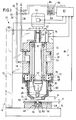
- einen Teillängsschnitt durch eine Nietmaschine als ein Beispiel für eine Vorrichtung zum maschinellen Durchführen einer mechanischen Verformung, bei der die beiden das Werkstück und das bzw. die Aufnahmeteile abtastenden Tastorgane in ihrer Ausgangsposition dargestellt sind,
- Fig. 2
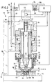
- einen Teillängsschnitt durch die Maschine gemäß Fig. 1 in dem Augenblick, in dem das voreilende erste Tastorgan auf das Aufnahmeteil aufsetzt, und
- Fig. 3
- einen Teillängsschnitt durch die Nietmaschine gemäß Fig. 1 in dem Zustand, in dem beide Tastorgane stillstehen, d.h. das eine Tastorgan das Werkstück und das andere Tastorgan das Aufnahmeteil kontaktiert.
- Fig. 1
- a partial longitudinal section through a riveting machine as an example of a device for mechanically performing a mechanical deformation, in which the two scan the workpiece and the receiving part or parts Feelers are shown in their starting position,
- Fig. 2
- a partial longitudinal section through the machine of FIG. 1 at the moment in which the leading first touch member touches the receiving part, and
- Fig. 3
- a partial longitudinal section through the riveting machine according to FIG. 1 in the state in which both sensing elements stand still, ie one sensing element contacts the workpiece and the other sensing element contacts the receiving part.
In Fig. 1 ist im Längsschnitt als Beispiel für eine Vorrichtung zur maschinellen Vornahme von mechanischen Kaltverformungsvorgängen eine Nietmaschine 10, teilweise im Längsschnitt, dargestellt. Die Nietmaschine 10 weist einen Tragrahmen 12 bzw. ein Gestell auf, das eine Auflagefläche 14 und einen Vertikal-Tragarm 16 aufweist, der mit der Auflagefläche 14 verbunden ist und rechtwinklig von dieser nach oben absteht. Am Tragarm 16 ist ein Maschinengehäuse 18 angebracht. In dem Maschinengehäuse 18 ist ein pneumatischer Kolben 20 verschiebbar gelagert. Der Kolben 20 ist parallel zur Erstreckung des Tragarms 16 rechtwinklig in Richtung auf die Auflagefläche 14 und umgekehrt dazu axial bewegbar. Der Kolben 20 weist einen radial nach außen abstehenden Flansch 22 auf, der sich in einem Hohlraum 24 des Maschinengehäuses 18 bewegt, wenn der Kolben 20 verfahren wird. Der Hohlraum 24 ist mit einer pneumatischen Druckleitung 26 und einer pneumatischen Entlüftungsleitung 28 verbunden. Bei Zuführung von Druckluft über die Druckleitung 26 wird der Kolben 20 gegen die Kraft einer (nicht dargestellten) Feder in Richtung auf die Auflagefläche 14 vorbewegt.1 shows a
Der Kolben 20 ist hohl ausgebildet und weist an seinen axialen Enden innenliegende Drehlager 30,32 für eine drehend antreibbare Antriebswelle 34 auf. Die Antriebswelle 34, die sich durch den Kolben 20 axial hindurch erstreckt, trägt an ihrem zur Auflagefläche 14 zugewandten unteren überstehenden Ende einen Werkzeughalter oder Nietkopf 36, der ein Nietwerkzeug 38 (Döpper) hält. Der Döpper ist an dem der Antriebswelle 34 abgewandten unteren Ende des Werkzeughalters 36 eingespannt gehalten. Das nach oben über den Kolben 20 überstehende Ende 40 der Antriebswelle 34 ist als Mehrkantprofil ausgebildet und von einer querschnittsgleichen Hülse 42 aufgenommen. Das obere Ende 40 ist gleitend verschiebbar von der Hülse 42 aufgenommen. Die Hülse 42 ist drehbar gelagert und von einem bei 34 angedeuteten Elektromotor angetrieben.The
Bei angesteuertem Elektromotor 44 treibt dieser die Hülse 42 an. Damit dreht sich der Werkzeughalter 36 und mit diesem das Nietwerkzeug 38. Eine Verformung bei sich drehendem Nietwerkzeug 38 wird durch Bewegen des Kolbens 20 in Richtung auf die Auflagefläche 14 bewirkt. Die axiale Länge der Hülse 42 und des Antriebswellenendes 40 ist derart bemessen, daß Hülse 42 und Antriebswelle 34 auch in der am weitesten ausgerückten untersten Stellung des Kolbens 20 noch in Eingriff miteinander sind. Bei der hier beschriebenen Nietmaschine 10 handelt es sich um eine Taumel- oder um eine Radialnietmaschine, bei der die Kaltverformung eines zu verformenden Werkstücks durch Aufbringen einer Andrückkraft, mit der das Nietwerkzeug 38 gegen das zu verformende Werkstück andrückt, und gleichzeitiger Taumel- oder Drehbewegung des Nietwerkzeuges 38 erfolgt.When the
In Fig. 1 ist bei 46 eine Aufnahme dargestellt, die auf der Auflagefläche 14 aufliegt und dort befestigt ist. Die Aufnahme 46 trägt ihrerseits die miteinander zu vernietenden Teile. In dem hier dargestellten Beispiel handelt es sich bei dem zu verformenden Werkstück um einen Gewindestehbolzen 48, der ein verjüngtes dem Nietwerkzeug 38 gegenüberliegendes Bolzenende 50 und einen eine Innengewindebohrung 52 tragenden Gewindeabschnitt 54 aufweist. Der verjüngte Abschnitt 50 erstreckt sich durch eine Öffnung in einem bei 56 angedeuteten Aufnahmeteil 56. Der zum Werkzeughalter 36 bzw. zum Nietwerkzeug 38 überstehende Teil des verjüngten Gewindebolzenabschnitts 50 (Überstand) wird durch Kaltverformung mittels des Nietwerkzeuges zum sogenannten Schließkopf verformt, der radial über die Öffnung in dem Aufnahmeteil 56 übersteht und dieses radial überragt. Die dem Werkzeughalter 36 und dem Nietwerkzeug 38 zugewandte Oberseite 58 der zu vernietenden Anordnung aus Gewindestehbolzen 48 und Aufnahmeteil 56 weist den für die Materialverformung erforderlichen Überstand 60 auf.In Fig. 1, a receptacle is shown at 46, which rests on the
In dem hier dargestellten und beschriebenen Ausführungsbeispiel ist lediglich ein Aufnahmeteil 56 (in Form einer Platte) dargestellt, mit dem der Gewindestehbolzen 48 (Werkstück) verbunden werden soll. Die Nietverbindung sorgt in diesem Fall für eine Halterung des Gewindestehbolzens 48 an dem Aufnahmeteil 56, bei dem es sich beispielsweise um eine Platte handelt. Im herkömmlichen Sinne werden Nieten dazu verwendet, um mehrere Teile miteinander zu verbinden. Bei einem solchen Anwendungsfall würde ein Niet z.B. zwei plattenförmige Aufnahmeteile miteinander verbinden, wobei der Kopf des Niets an dem einen Aufnahmeteil anliegt und sich der Nietschaft durch miteinander fluchtende Öffnungen in beiden oder den mehreren Aufnahmeteilen hindurch erstreckt.In the exemplary embodiment shown and described here, only a receiving part 56 (in the form of a plate) is shown, with which the threaded stud 48 (workpiece) is to be connected. In this case, the rivet connection ensures that the threaded
Am unteren Ende des Kolbens 20 ist eine den Werkzeughalter 36 sammt Nietwerkzeug 38 mit Abstand radial umgebende Tasthülse 62 angeordnet. Die Tasthülse 62 ist in einer Ringnut 64 des Kolbens 20 unverlierbar aufgenommen. Die Ringnut 64 ist an dem unteren Ende des Kolbens 20 radial nach außen versetzt angeordnet. Im Bereich der Ringnut 64, in dem der Kolben 20 einen vergrößerten Durchmesser aufweist, ist der Kolben 20 außerhalb des Maschinengehäuses 18 angeordnet. Die Tasthülse 62 erstreckt sich in axialer Verlängerung des Kolbens 20 bis über das Nietwerkzeug 38 hinaus. An ihrem dem Kolben 20 abgewandten unteren Ende verjüngt sich die Tasthülse 62 und weist eine ringförmige Stirnfläche 66 auf. Zwischen dem in die Ringnut 64 eingetauchten Ende 68 der Tasthülse 62 und dem Grund 70 der Ringnut 64 ist eine Schraubendruckfeder 72 angeordnet. Diese Schraubendruckfeder 72 spannt die Tasthülse 62 in Richtung auf die Auflagefläche 14 des Tragrahmens 12 vor.At the lower end of the
Wie in der Ausgangsposition der Nietmaschine gemäß Fig. 1 zu erkennen ist, ragt die ringförmige Stirnfläche 66 der Tasthülse 62 über die Stirnfläche 74 des Nietwerkzeuges 38 vor. Der axiale Abstand a dieser beiden Flächen, d.h. der Abstand dieser beiden Flächen in Bewegungsrichtung des Kolbens 20, ist größer als der (Ist-)Überstand b, um den der verjüngte Abstand 50 des Gewindestehbolzens 48 über die Oberseite 58 des Aufnahmeteils 56 übersteht.As can be seen in the starting position of the riveting machine according to FIG. 1, the annular end face 66 of the
Die Nietmaschine 10 ist ferner mit einem Weggeber 76 versehen, der die Verschiebung des Kolbens 20 relativ zum Maschinengehäuse 18 mißt. Das Maß, um das sich die Tasthülse 62 gegen die Kraft der Schraubendruckfeder 72 relativ zum Kolben 20 bewegen kann, wird meßtechnisch mittels eines Weggebers 78 ermittelt. Schließlich weist die Maschine 10 noch einen in Form eines Dehnmeßstreifens vorliegenden Detektor 80 zur Messung mechanischer Spannungen des Tragrahmens 12 auf. Auf die Funktion dieses Detektors 80 wird weiter unten noch eingegangen werden. Die beiden Weggeber 76 und 78 sowie der Detektor 80 sind mit einer Auswerteschaltung 82 verbunden, die die Ausgangssignale der Weggeber und des Detektors empfängt. Die Auswerteschaltung 82 ist darüber hinaus elektrisch mit dem Motor 44 verbunden, um diesen anzusteuern, insbesondere ein- und auszuschalten. Mit der Auswerteschaltung 82 ist ferner eine Anzeige-/Dateneingabevorrichtung 84 verbunden, die einen Anzeigeteil 86 und ein Tastenfeld 88 für die Dateneingabe aufweist. Schließlich ist die Auswerteschaltung 82 mit Steuerventilen 90,92 für die Druckleitung 26 und die Entlüftungsleitung 28 verbunden, um diese Leitungen freizugeben bzw. zu sperren.The
Mit der hier beschriebenen Nietmaschine 10 läßt sich in der Phase unmittelbar vor dem Kaltverformungsvorgang überprüfen, ob die miteinander zu vernietenden Teile sich auf der Auflagefläche 14 bzw. in der Aufnahme 46 der Auflagefläche 14 befinden, ob der (Ist-)Überstand b unter Berücksichtigung von Toleranzen einem vorgegebenen Sollwert entspricht und ob die zu vernietenden Teile die geforderten Sollabmessungen aufweisen. Zur Überprüfung all dieser Vorgaben arbeitet die Nietmaschine 10 wie folgt.With the
Ausgehend aus der Ausgangsposition gemäß Fig. 1 werden durch entsprechende Ausgangssignale der Auswerteschaltung 82 die Steuerventile 90 und 92 geöffnet, womit der Kolben 20 in Richtung des Pfeils 94 auf die Auflagefläche 14 zubewegt wird. Mit dem Kolben 20 bewegen sich folglich auch das Nietwerkzeug 38 in Richtung auf den Gewindestehbolzen 48 und die Tasthülse 62 in Richtung auf das Auflageteil 56. Während dieser Phase der Vorbewegung steht das Nietwerkzeug 38 still.Starting from the starting position according to FIG. 1, the
Diese Vorbewegung des Kolbens 20 bei stillstehendem Nietwerkzeug 38 hält an, bis sowohl die ringförmige Stirnfläche 66 der Tasthülse 62 das Aufnahmeteil 56 als auch die Stirnfläche 74 des Nietwerkzeuges 38 den Gewindestehbolzen 48 kontaktiert hat. Die Situation bei Kontaktierung der Tasthülse 62 und des Aufnahmeteils 56 ist in Fig. 2 dargestellt. Da der axiale Versatz zwischen der ringförmigen Stirnfläche 66 der Tasthülse 62 und der Stirnfläche 74 des Nietwerkzeuges 38 größer ist als der zu erwartende Überstand des verjüngten Abschnitts 50 des Gewindestehbolzens 48 über das Aufnahmeteil 56, verbleibt bei bereits durch die Tasthülse 62 kontaktiertem Aufnahmeteil 56 zwischen dem Nietwerkzeug 38 und dem oberen Ende des Gewindestehbolzens 48 noch ein Abstand c, der gleich der Differenz der in Fig. 1 eingezeichneten Abstände a und b ist. Die Tasthülse 62 läßt sich nun nicht mehr weiter vorbewegen, wenn der Kolben 20 sich in Richtung des Pfeils 94 weiterbewegt. Daher kommt es zu einer Relativbewegung zwischen dem Kolben 20 und der Tasthülse 62 unter Komprimierung der Schraubendruckfeder 72; anders ausgedrückt bewegt sich also die Tasthülse 62 in Bezug auf den Kolben 20 zu dessen rückwärtigen Ende hin. Auch während dieser Phase der Vorbewegung des Kolbens 20 steht das Nietwerkzeug 38 still.This forward movement of the
Die Vorbewegung des Kolbens 20 findet in dem Augenblick ihr (vorläufiges) Ende, in dem die Stirnfläche 74 auf den Gewindestehbolzen 48 aufsetzt. Dieses Aufsetzen wird in der Auswerteschaltung 82 erkannt. Es wird sich nämlich zwischen dem Maschinengehäuse 18 und dem Tragarm 16 eine mechanische Spannung als Reaktion auf die weiterhin auf den Kolben 20 wirkende Antriebskraft bei an dem Gewindestehbolzen 48 anliegendem Nietwerkzeug 38 einstellen. Der zwischen dem Maschinengehäuse 18 und dem Tragarm 16 angeordnete Detektor 80 mißt diese ansteigende mechanische Spannung. In der Auswerteschaltung 82 wird das Meßsignal des Detektors 80 mit einem Schwellwert verglichen. Übersteigt das Ausgangssignal des Detektors 80 den Schwellwert, so interpretiert die Auswerteschaltung 82 dies als ein Aufsetzen des Nietwerkzeuges 38 auf den Gewindestehbolzen 48. In diesem Zustand befindet sich die Nietmaschine 10 in der in Fig. 3 zeichnerisch dargestellten Situation. Sowohl die ringförmige Stirnfläche 66 der Tasthülse 62 als auch die Stirnfläche 74 des Nietwerkzeuges 38 liegen an dem Aufnahmeteil 56 bzw. dem Gewindestehbolzen 48 an. Mittels des Weggebers 78, dessen Ausgangssignal der Auswerteschaltung 82 zugeführt ist, kann nun ermittelt werden, um welchen Betrag ausgehend von der Ausgangsposition sich die Tasthülse 62 relativ zum Kolben 20 bewegt hat. Da der Abstand a der beiden Flächen 66 und 74 in der Ausgangsposition bekannt ist und die Verschiebung der Tasthülse 62 relativ zum Kolben 20 meßtechnisch erfaßt ist, kann nun der Abstand der Flächen 66 und 74 ermittelt werden. Dieser Abstand entspricht exakt dem Ist-Überstand b (s. Fig. 3). Durch Vergleich mit einem Soll-Überstand, der zuvor über das Tastenfeld 88 in die Auswerteschaltung 82 eingegeben worden ist, kann nun überprüft werden, ob der Ist-Überstand b größer oder kleiner als oder gleich dem Soll-Überstand ist. Unter Berücksichtigung eines ebenfalls in die Auswerteschaltung 82 eingegebenen Toleranzbereichs kann damit die Aussage getroffen werden, ob sich der Ist-Überstand b innerhalb der vorgegebenen Toleranz befindet. Sofern dies nicht der Fall ist, erzeugt die Auswerteschaltung ein diesen Zustand anzeigendes Fehlersignal, das an der Anzeige 86 eine entsprechende optische Anzeige erzeugt; zusätzlich kann auch eine akustische Anzeige erfolgen. Im übrigen wird der Arbeitszyklus der Nietmaschine 10 abgebrochen.The advancement of the
Liegt der Ist-Überstand b innerhalb des vorgegebenen Toleranzbereichs, so kann je nach Ausführung der Nietmaschine in einem nächsten Schritt überprüft werden, ob der Gewindestehbolzen 48 und das Aufnahmeteil 56 die vorgegebenen Erstreckungen in Bewegungsrichtung des Kolbens 20 aufweisen. Dazu wird zunächst anhand des Ausgangssignals des Weggebers 76 die zurückgelegte Gesamtwegstrecke d des Kolbens 20 ermittelt (s. Fig. 3). Bei bekannter Ausgangsposition des Kolbens 20 relativ zur Auflagefläche 14 bzw. zur Aufnahme 46 kann dann anhand des zurückgelegten Gesamtweges d festgestellt werden, welche axiale Länge der Gewindestehbolzen 48 aufweist. Durch Vergleich mit einem Sollwert kann unter Berücksichtigung eines ebenfalls vorgegebenen Toleranzbereichs entschieden werden, ob der Gewindestehbolzen 48 eine innerhalb der Toleranz liegende axiale Länge aufweist. Anhand der von dem Weggeber 76 erfaßten Gesamtwegstrecke d und der von dem Weggeber 78 gemessenen Relativ-Wegstrecke kann bei definierter Ausgangsposition von Kolben 20 und Tasthülse 62 relativ zueinander sowie in Bezug auf die Auflagefläche 14 bzw. die Aufnahme 46 die Stärke bzw. Dicke (Erstreckung in Bewegungsrichtung 94) des Aufnahmeteils 56 ermittelt werden. Der so ermittelte Wert wird unter Berücksichtigung von ebenfalls vorgegebenen Toleranzen mit einem Sollwert verglichen, um zu überprüfen, ob die Dicke des Aufnahmeteils 56 innerhalb der Toleranz liegt. Ist dies nicht der Fall, erzeugt die Auswerteschaltung 82 ein diesen Zustand anzeigendes optisches und/oder akustisches Fehlersignal. Ferner wird der Arbeitszyklus der Nietmaschine 10 abgebrochen.If the actual overhang b lies within the predetermined tolerance range, depending on the design of the riveting machine, it can be checked in a next step whether the threaded
Erst wenn die obige Überprüfung der Höhendifferenz zwischen Niet- und Aufnahmeteil und die Überprüfung der Absolutlänge des Niets (sofern ausgeführt) positiv verlaufen ist, schaltet die Auswerteschaltung 82 den Elektromotor 44 zur Rotation des Nietwerkzeuges 38 ein. Infolge der Anpreßkraft, mit der der Kolben 20 gegen den Gewindestehbolzen 48 gedrückt gehalten wird, kommt es zu einer Kaltverformung und Stauchung des überstehenden verjüngten Abschnitts 50 des Gewindestehbolzens 48. Der zusätzliche Verschiebungsweg des Kolbens 20, den dieser infolge der Kaltverformung des Gewindestehbolzens 48 zurücklegt, kann, wenn dies gewünscht wird, meßtechnisch über den Weggeber 76 erfaßt werden. Ferner kann mit Beginn der Einschaltung des Elektromotors 44 in der Auswerteschaltung 82 eine Zeitmessung erfolgen. Benötigt der Kolben 20 zum Zurücklegen einer Soll-Zusatzwegstrecke länger als eine vorgegebene Minimalzeit und weniger als eine vorgegebene Maximalzeit, so ist die Vernietung ordnungsgemäß erfolgt und die Nietmaschine 10 wird ohne jede weitere Informationsanzeige bzw. mit der Informationsanzeige "Nietung in Ordnung" deaktiviert. Erfolgt dagegen die Verformung innerhalb einer kürzeren Zeit der Minimalzeit, d.h. erreicht der Kolben 20 die Soll-Zusatzwegstrecke schneller als durch die Minimalzeit vorgegeben, so läßt das darauf schließen, daß das Material des Gewindestehbolzens 48 zu weich ist. Umgekehrt kann auf zu hartes Materials des Gewindestehbolzens 48 geschlossen werden, wenn der Kolben 20 bis zum Ablauf der Maximalzeit seine Soll-Zusatzwegstrecke noch nicht zurückgelegt hat. In beiden diesen Fällen wird der Verformungsvorgang mit einer Fehleranzeige abgebrochen.Only when the above check of the height difference between the rivet part and the receiving part and the check of the absolute length of the rivet (if carried out) has proceeded positively, does the
Mit der hier beschriebenen Nietmaschine 10 ist ein Weg aufgezeichnet, mit dem sich vor Ort, d.h. unmittelbar vor dem Verformungsvorgang überprüfen läßt, ob die zu verbindenden Teile ordnungsgemäße Relativabmessungen und ordnungsgemäße Absolutabmessungen aufweisen. Damit ist ein weiterer Schritt in Richtung Qualitätssicherung und Qualitätsverbesserung von durch Kaltverformung erfolgten Verbindungen gemacht.With the
Claims (13)
Applications Claiming Priority (2)
| Application Number | Priority Date | Filing Date | Title |
|---|---|---|---|
| DE4431091 | 1994-09-01 | ||
| DE4431091 | 1994-09-01 |
Publications (2)
| Publication Number | Publication Date |
|---|---|
| EP0699490A1 true EP0699490A1 (en) | 1996-03-06 |
| EP0699490B1 EP0699490B1 (en) | 1998-03-04 |
Family
ID=6527129
Family Applications (1)
| Application Number | Title | Priority Date | Filing Date |
|---|---|---|---|
| EP95112263A Revoked EP0699490B1 (en) | 1994-09-01 | 1995-08-04 | Control device, in particular for forming machines |
Country Status (3)
| Country | Link |
|---|---|
| EP (1) | EP0699490B1 (en) |
| AT (1) | ATE163582T1 (en) |
| DE (1) | DE59501529D1 (en) |
Cited By (5)
| Publication number | Priority date | Publication date | Assignee | Title |
|---|---|---|---|---|
| EP0820823A1 (en) * | 1996-07-25 | 1998-01-28 | Bodmer Küsnacht AG | Checking device, especially for forming machines |
| EP0826443A2 (en) * | 1996-08-30 | 1998-03-04 | Baltec Maschinenbau Ag | Device for controlling the stroke of a riveting machine |
| DE102013208288A1 (en) * | 2013-05-06 | 2014-11-06 | Adolf Würth GmbH & Co. KG | Fastener-selective contact pressure detector for a setting device for setting the fastening element |
| JP2019508255A (en) * | 2016-03-18 | 2019-03-28 | バルテック マシネンバウ アーゲーBalTec Maschinenbau AG | Device for applying an applied force to a connecting element |
| CN110508739A (en) * | 2019-08-15 | 2019-11-29 | 深圳市盛格纳电子有限公司 | Riveting press equipment |
Citations (6)
| Publication number | Priority date | Publication date | Assignee | Title |
|---|---|---|---|---|
| DE2906922A1 (en) * | 1979-02-22 | 1980-09-04 | Steinel Bernhard Werkzeugmasch | Safety device for riveting machine - has switch actuated by pressure of riveting head on operator's hand |
| DE3715905C2 (en) | 1987-05-13 | 1993-04-15 | Maschinen- Und Werkzeugbau D. Friedrich Gmbh & Co Kg, 7064 Remshalden, De | |
| EP0539045A1 (en) * | 1991-10-25 | 1993-04-28 | Gemcor Engineering Corp. | Method and apparatus for fastening |
| DE4213421A1 (en) * | 1992-04-23 | 1993-10-28 | Fraunhofer Ges Forschung | Riveting tool with tilting head - has rotary drive for head mounted on vertically moving carriage |
| US5331831A (en) * | 1993-03-19 | 1994-07-26 | Bermo, Inc. | Hardware sensor |
| JPH06277786A (en) * | 1993-03-26 | 1994-10-04 | Oi Seisakusho Co Ltd | Rivet fastening mechanism |
-
1995
- 1995-08-04 AT AT95112263T patent/ATE163582T1/en active
- 1995-08-04 DE DE59501529T patent/DE59501529D1/en not_active Revoked
- 1995-08-04 EP EP95112263A patent/EP0699490B1/en not_active Revoked
Patent Citations (6)
| Publication number | Priority date | Publication date | Assignee | Title |
|---|---|---|---|---|
| DE2906922A1 (en) * | 1979-02-22 | 1980-09-04 | Steinel Bernhard Werkzeugmasch | Safety device for riveting machine - has switch actuated by pressure of riveting head on operator's hand |
| DE3715905C2 (en) | 1987-05-13 | 1993-04-15 | Maschinen- Und Werkzeugbau D. Friedrich Gmbh & Co Kg, 7064 Remshalden, De | |
| EP0539045A1 (en) * | 1991-10-25 | 1993-04-28 | Gemcor Engineering Corp. | Method and apparatus for fastening |
| DE4213421A1 (en) * | 1992-04-23 | 1993-10-28 | Fraunhofer Ges Forschung | Riveting tool with tilting head - has rotary drive for head mounted on vertically moving carriage |
| US5331831A (en) * | 1993-03-19 | 1994-07-26 | Bermo, Inc. | Hardware sensor |
| JPH06277786A (en) * | 1993-03-26 | 1994-10-04 | Oi Seisakusho Co Ltd | Rivet fastening mechanism |
Non-Patent Citations (1)
| Title |
|---|
| PATENT ABSTRACTS OF JAPAN vol. 94, no. 010 * |
Cited By (7)
| Publication number | Priority date | Publication date | Assignee | Title |
|---|---|---|---|---|
| EP0820823A1 (en) * | 1996-07-25 | 1998-01-28 | Bodmer Küsnacht AG | Checking device, especially for forming machines |
| EP0826443A2 (en) * | 1996-08-30 | 1998-03-04 | Baltec Maschinenbau Ag | Device for controlling the stroke of a riveting machine |
| EP0826443A3 (en) * | 1996-08-30 | 1999-06-16 | Baltec Maschinenbau Ag | Device for controlling the stroke of a riveting machine |
| DE102013208288A1 (en) * | 2013-05-06 | 2014-11-06 | Adolf Würth GmbH & Co. KG | Fastener-selective contact pressure detector for a setting device for setting the fastening element |
| EP2801422A2 (en) | 2013-05-06 | 2014-11-12 | Adolf Würth GmbH & Co. KG | Fastener selective pressure detector for a fastener setting device |
| JP2019508255A (en) * | 2016-03-18 | 2019-03-28 | バルテック マシネンバウ アーゲーBalTec Maschinenbau AG | Device for applying an applied force to a connecting element |
| CN110508739A (en) * | 2019-08-15 | 2019-11-29 | 深圳市盛格纳电子有限公司 | Riveting press equipment |
Also Published As
| Publication number | Publication date |
|---|---|
| DE59501529D1 (en) | 1998-04-09 |
| ATE163582T1 (en) | 1998-03-15 |
| EP0699490B1 (en) | 1998-03-04 |
Similar Documents
| Publication | Publication Date | Title |
|---|---|---|
| EP1064111B1 (en) | Method for controlling, monitoring and checking a forming operation of a metal-forming machine tool, especially a riveting machine | |
| EP1409190B1 (en) | Resistance welding device and control method | |
| EP2715884B1 (en) | Process and arrangement for a weighted monitoring the wear of a hand tool for crimping workpieces | |
| EP1641586B1 (en) | Method and device for pressure welding, which takes into account deviations in the length of workpieces | |
| DE19521369A1 (en) | Processing machine and method for forming workpieces | |
| EP0983495A1 (en) | Method and device for conducting a hardness test on test specimens, specially tablets or pills | |
| DE3537234C2 (en) | ||
| EP0482360A2 (en) | Motor-driven press with load and displacement sensors | |
| DE3715905C2 (en) | ||
| EP0820823B1 (en) | Checking device, especially for forming machines | |
| EP0699490B1 (en) | Control device, in particular for forming machines | |
| EP0611612A1 (en) | Spinning machine | |
| EP0714481B1 (en) | Device and process for setting valve travel | |
| DE102005013746B4 (en) | Back corrugated Roll | |
| WO2020207645A1 (en) | Method and measuring device for measuring or calibrating utensils in pressing processes | |
| DE19744227A1 (en) | Device and method for carrying out a hardness test on test specimens, in particular tablets or pills | |
| DE102006015581B3 (en) | Deformation process implementing method, involves determining temporal sequences of motor current as measure for force or torque of direct drive by integrating measuring device in direct drive | |
| DE19516643C1 (en) | Highly accurate force and distance measuring head which determines broad range of physical properties | |
| EP2555888A1 (en) | Tool unit of a rotary kneading machine | |
| EP1516689A1 (en) | Device and method of ultrasonic welding of workpieces like electrical wires, in particular strands | |
| EP0826443A2 (en) | Device for controlling the stroke of a riveting machine | |
| DE4301309C2 (en) | Cutting press | |
| DE102004014255B3 (en) | Flat cheek profile rolling tool, includes sensor(s) for determining tracking error force between rolling cheeks and rolled workpiece fed between them | |
| CH689299A5 (en) | Machine deformation for rivet elements | |
| DE3127462A1 (en) | Method and device for diagnosing incorrect operation and/or defective tools on a machine for the forming of metallic blanks, in particular on a thread rolling machine |
Legal Events
| Date | Code | Title | Description |
|---|---|---|---|
| PUAI | Public reference made under article 153(3) epc to a published international application that has entered the european phase |
Free format text: ORIGINAL CODE: 0009012 |
|
| AK | Designated contracting states |
Kind code of ref document: A1 Designated state(s): AT DE FR GB IT |
|
| 17P | Request for examination filed |
Effective date: 19960502 |
|
| GRAG | Despatch of communication of intention to grant |
Free format text: ORIGINAL CODE: EPIDOS AGRA |
|
| 17Q | First examination report despatched |
Effective date: 19970527 |
|
| GRAG | Despatch of communication of intention to grant |
Free format text: ORIGINAL CODE: EPIDOS AGRA |
|
| GRAH | Despatch of communication of intention to grant a patent |
Free format text: ORIGINAL CODE: EPIDOS IGRA |
|
| GRAH | Despatch of communication of intention to grant a patent |
Free format text: ORIGINAL CODE: EPIDOS IGRA |
|
| GRAA | (expected) grant |
Free format text: ORIGINAL CODE: 0009210 |
|
| AK | Designated contracting states |
Kind code of ref document: B1 Designated state(s): AT DE FR GB IT |
|
| REF | Corresponds to: |
Ref document number: 163582 Country of ref document: AT Date of ref document: 19980315 Kind code of ref document: T |
|
| ITF | It: translation for a ep patent filed |
Owner name: ING. A. GIAMBROCONO & C. S.R.L. |
|
| REF | Corresponds to: |
Ref document number: 59501529 Country of ref document: DE Date of ref document: 19980409 |
|
| ET | Fr: translation filed | ||
| GBT | Gb: translation of ep patent filed (gb section 77(6)(a)/1977) |
Effective date: 19980506 |
|
| PGFP | Annual fee paid to national office [announced via postgrant information from national office to epo] |
Ref country code: FR Payment date: 19980817 Year of fee payment: 4 |
|
| PGFP | Annual fee paid to national office [announced via postgrant information from national office to epo] |
Ref country code: AT Payment date: 19980821 Year of fee payment: 4 |
|
| PGFP | Annual fee paid to national office [announced via postgrant information from national office to epo] |
Ref country code: DE Payment date: 19980925 Year of fee payment: 4 |
|
| PLBQ | Unpublished change to opponent data |
Free format text: ORIGINAL CODE: EPIDOS OPPO |
|
| PLBI | Opposition filed |
Free format text: ORIGINAL CODE: 0009260 |
|
| 26 | Opposition filed |
Opponent name: MASCHINEN- UND WERKZEUGBAU DOROTHEA FRIEDRICH GMB Effective date: 19981007 |
|
| PLBF | Reply of patent proprietor to notice(s) of opposition |
Free format text: ORIGINAL CODE: EPIDOS OBSO |
|
| PLBF | Reply of patent proprietor to notice(s) of opposition |
Free format text: ORIGINAL CODE: EPIDOS OBSO |
|
| PLBF | Reply of patent proprietor to notice(s) of opposition |
Free format text: ORIGINAL CODE: EPIDOS OBSO |
|
| PG25 | Lapsed in a contracting state [announced via postgrant information from national office to epo] |
Ref country code: GB Free format text: LAPSE BECAUSE OF NON-PAYMENT OF DUE FEES Effective date: 19990804 |
|
| RDAH | Patent revoked |
Free format text: ORIGINAL CODE: EPIDOS REVO |
|
| RDAG | Patent revoked |
Free format text: ORIGINAL CODE: 0009271 |
|
| STAA | Information on the status of an ep patent application or granted ep patent |
Free format text: STATUS: PATENT REVOKED |
|
| GBPC | Gb: european patent ceased through non-payment of renewal fee |
Effective date: 19990804 |
|
| 27W | Patent revoked |
Effective date: 19991119 |