EP0696231B1 - Dispositif ameliore destine a des dosages immunologiques chimioluminescents automatiques - Google Patents
Dispositif ameliore destine a des dosages immunologiques chimioluminescents automatiques Download PDFInfo
- Publication number
- EP0696231B1 EP0696231B1 EP94914865A EP94914865A EP0696231B1 EP 0696231 B1 EP0696231 B1 EP 0696231B1 EP 94914865 A EP94914865 A EP 94914865A EP 94914865 A EP94914865 A EP 94914865A EP 0696231 B1 EP0696231 B1 EP 0696231B1
- Authority
- EP
- European Patent Office
- Prior art keywords
- well
- matrix
- assay
- fibrous matrix
- transfer
- Prior art date
- Legal status (The legal status is an assumption and is not a legal conclusion. Google has not performed a legal analysis and makes no representation as to the accuracy of the status listed.)
- Expired - Lifetime
Links
Images


Classifications
-
- G—PHYSICS
- G01—MEASURING; TESTING
- G01N—INVESTIGATING OR ANALYSING MATERIALS BY DETERMINING THEIR CHEMICAL OR PHYSICAL PROPERTIES
- G01N33/00—Investigating or analysing materials by specific methods not covered by groups G01N1/00 - G01N31/00
- G01N33/48—Biological material, e.g. blood, urine; Haemocytometers
- G01N33/50—Chemical analysis of biological material, e.g. blood, urine; Testing involving biospecific ligand binding methods; Immunological testing
- G01N33/53—Immunoassay; Biospecific binding assay; Materials therefor
- G01N33/543—Immunoassay; Biospecific binding assay; Materials therefor with an insoluble carrier for immobilising immunochemicals
- G01N33/54366—Apparatus specially adapted for solid-phase testing
-
- B—PERFORMING OPERATIONS; TRANSPORTING
- B01—PHYSICAL OR CHEMICAL PROCESSES OR APPARATUS IN GENERAL
- B01L—CHEMICAL OR PHYSICAL LABORATORY APPARATUS FOR GENERAL USE
- B01L3/00—Containers or dishes for laboratory use, e.g. laboratory glassware; Droppers
- B01L3/50—Containers for the purpose of retaining a material to be analysed, e.g. test tubes
- B01L3/502—Containers for the purpose of retaining a material to be analysed, e.g. test tubes with fluid transport, e.g. in multi-compartment structures
- B01L3/5023—Containers for the purpose of retaining a material to be analysed, e.g. test tubes with fluid transport, e.g. in multi-compartment structures with a sample being transported to, and subsequently stored in an absorbent for analysis
-
- B—PERFORMING OPERATIONS; TRANSPORTING
- B01—PHYSICAL OR CHEMICAL PROCESSES OR APPARATUS IN GENERAL
- B01L—CHEMICAL OR PHYSICAL LABORATORY APPARATUS FOR GENERAL USE
- B01L3/00—Containers or dishes for laboratory use, e.g. laboratory glassware; Droppers
- B01L3/50—Containers for the purpose of retaining a material to be analysed, e.g. test tubes
- B01L3/502—Containers for the purpose of retaining a material to be analysed, e.g. test tubes with fluid transport, e.g. in multi-compartment structures
- B01L3/5025—Containers for the purpose of retaining a material to be analysed, e.g. test tubes with fluid transport, e.g. in multi-compartment structures for parallel transport of multiple samples
- B01L3/50255—Multi-well filtration
-
- B—PERFORMING OPERATIONS; TRANSPORTING
- B01—PHYSICAL OR CHEMICAL PROCESSES OR APPARATUS IN GENERAL
- B01L—CHEMICAL OR PHYSICAL LABORATORY APPARATUS FOR GENERAL USE
- B01L2300/00—Additional constructional details
- B01L2300/06—Auxiliary integrated devices, integrated components
- B01L2300/0681—Filter
-
- B—PERFORMING OPERATIONS; TRANSPORTING
- B01—PHYSICAL OR CHEMICAL PROCESSES OR APPARATUS IN GENERAL
- B01L—CHEMICAL OR PHYSICAL LABORATORY APPARATUS FOR GENERAL USE
- B01L2300/00—Additional constructional details
- B01L2300/06—Auxiliary integrated devices, integrated components
- B01L2300/069—Absorbents; Gels to retain a fluid
-
- B—PERFORMING OPERATIONS; TRANSPORTING
- B01—PHYSICAL OR CHEMICAL PROCESSES OR APPARATUS IN GENERAL
- B01L—CHEMICAL OR PHYSICAL LABORATORY APPARATUS FOR GENERAL USE
- B01L2300/00—Additional constructional details
- B01L2300/08—Geometry, shape and general structure
- B01L2300/0809—Geometry, shape and general structure rectangular shaped
- B01L2300/0829—Multi-well plates; Microtitration plates
-
- B—PERFORMING OPERATIONS; TRANSPORTING
- B01—PHYSICAL OR CHEMICAL PROCESSES OR APPARATUS IN GENERAL
- B01L—CHEMICAL OR PHYSICAL LABORATORY APPARATUS FOR GENERAL USE
- B01L2400/00—Moving or stopping fluids
- B01L2400/04—Moving fluids with specific forces or mechanical means
- B01L2400/0403—Moving fluids with specific forces or mechanical means specific forces
- B01L2400/0406—Moving fluids with specific forces or mechanical means specific forces capillary forces
-
- Y—GENERAL TAGGING OF NEW TECHNOLOGICAL DEVELOPMENTS; GENERAL TAGGING OF CROSS-SECTIONAL TECHNOLOGIES SPANNING OVER SEVERAL SECTIONS OF THE IPC; TECHNICAL SUBJECTS COVERED BY FORMER USPC CROSS-REFERENCE ART COLLECTIONS [XRACs] AND DIGESTS
- Y10—TECHNICAL SUBJECTS COVERED BY FORMER USPC
- Y10S—TECHNICAL SUBJECTS COVERED BY FORMER USPC CROSS-REFERENCE ART COLLECTIONS [XRACs] AND DIGESTS
- Y10S435/00—Chemistry: molecular biology and microbiology
- Y10S435/81—Packaged device or kit
-
- Y—GENERAL TAGGING OF NEW TECHNOLOGICAL DEVELOPMENTS; GENERAL TAGGING OF CROSS-SECTIONAL TECHNOLOGIES SPANNING OVER SEVERAL SECTIONS OF THE IPC; TECHNICAL SUBJECTS COVERED BY FORMER USPC CROSS-REFERENCE ART COLLECTIONS [XRACs] AND DIGESTS
- Y10—TECHNICAL SUBJECTS COVERED BY FORMER USPC
- Y10S—TECHNICAL SUBJECTS COVERED BY FORMER USPC CROSS-REFERENCE ART COLLECTIONS [XRACs] AND DIGESTS
- Y10S436/00—Chemistry: analytical and immunological testing
- Y10S436/805—Optical property
-
- Y—GENERAL TAGGING OF NEW TECHNOLOGICAL DEVELOPMENTS; GENERAL TAGGING OF CROSS-SECTIONAL TECHNOLOGIES SPANNING OVER SEVERAL SECTIONS OF THE IPC; TECHNICAL SUBJECTS COVERED BY FORMER USPC CROSS-REFERENCE ART COLLECTIONS [XRACs] AND DIGESTS
- Y10—TECHNICAL SUBJECTS COVERED BY FORMER USPC
- Y10S—TECHNICAL SUBJECTS COVERED BY FORMER USPC CROSS-REFERENCE ART COLLECTIONS [XRACs] AND DIGESTS
- Y10S436/00—Chemistry: analytical and immunological testing
- Y10S436/807—Apparatus included in process claim, e.g. physical support structures
- Y10S436/809—Multifield plates or multicontainer arrays
-
- Y—GENERAL TAGGING OF NEW TECHNOLOGICAL DEVELOPMENTS; GENERAL TAGGING OF CROSS-SECTIONAL TECHNOLOGIES SPANNING OVER SEVERAL SECTIONS OF THE IPC; TECHNICAL SUBJECTS COVERED BY FORMER USPC CROSS-REFERENCE ART COLLECTIONS [XRACs] AND DIGESTS
- Y10—TECHNICAL SUBJECTS COVERED BY FORMER USPC
- Y10S—TECHNICAL SUBJECTS COVERED BY FORMER USPC CROSS-REFERENCE ART COLLECTIONS [XRACs] AND DIGESTS
- Y10S436/00—Chemistry: analytical and immunological testing
- Y10S436/807—Apparatus included in process claim, e.g. physical support structures
- Y10S436/81—Tube, bottle, or dipstick
Definitions
- the present invention is directed toward an improved device for use in chemiluminescent immunoassays (CLIA).
- CLIA chemiluminescent immunoassays
- the present invention improves the direct measurement of a chemiluminescent signal from a solid surface.
- the present invention relates to an apparatus for use in heterogeneous immunoassay wherein a chemiluminescent signal provided by the immobilized product of an immunochemical reaction from a porous matrix is measured.
- the improvement relates to the reduction of background chemiluminescent signals which improves the sensitivity, precision and accuracy of chemiluminescent assays.
- Solid phase immunoassay procedures are preferred over other diagnostic methods because of their specificity and sensitivity as interfering substances can be washed away before optical readout.
- One form of a conventional solid-phase immunoassay is a "sandwich assay" which involves contacting a test sample suspected of containing an antibody or antigen with a material which has attached to it a protein or another substance capable of binding the antigen or the antibody to the surface of the support. After the antibody or antigen is bound to the support material it is treated with a second antigen or antibody, which is conjugated with an enzyme, a fluorophore or a chemiluminescent label. The second antigen or antibody then becomes bound to the corresponding antibody or antigen on the support.
- an indicator substance for example, a chromogenic substrate, is added which reacts with the enzyme to produce a color change.
- the color change can be observed visually or more preferably by an instrument to indicate the presence or absence of the antibody or antigen in the sample.
- fluorescent labeled moieties can be monitored by using excitation at an appropriate wavelength, while chemiluminescent labeled antigens or antibodies can be followed after reaction by chemically activating the chemiluminescent labels to generate light which can be detected by photometric means.
- U.S. Patent 4,632,910 discloses an apparatus having a porous filter containing a bound receptor for complexing an analyte.
- an absorbent material is positioned below the porous filter to assist the fluid sample in flowing through the filter.
- a labeled antibody is then added to the porous filter to detect the presence or absence of the analyte.
- European Patent Application No. 0131934 discloses an assay device having a plurality of aligned adjacent incubation wells located on its top surface which empty through a filter membrane located above a waste reservoir.
- US Patent 4,652,533 discloses an assay method using such a device.
- a solid-phase fluorescent immunoassay reaction mixture is placed in the well and drawn through the membrane by applying reduced pressure to the waste reservoir to separate a solid-phase reaction product from a liquid-phase reactants so that the solid-phase reaction product can be observed.
- This approach has serious limitations. First, it is limited to use of microparticles as a capture phase. Second, the sample, conjugate and microparticles are incubated in the same incubation well that the optical reading takes place.
- Non-specific binding of sample and conjugate, labeled antigen or antibody, to the membrane filter in the reading well and the wall of the well can occur and contribute to the background of the assay and limiting assay sensitivity.
- Other microparticle based vacuum filtration devices for immunoassays are available commercially such as Millititer® Plate from Millipore Corporation, Bedford, MA.
- US Patent 5,006,309 and EP-A-0 424 633 disclose devices having an incubation well and read well with a porous matrix and means positioned below the porous matrix to enhance the flow of sample and assay reaction mixtures through the porous matrix.
- the assay reagents are incubated in the incubation well and then transferred to the read well where capture reagent/analyte complexes are immobilized on the matrix.
- US Patent 5,089,424 discloses devices and methods for performing chemiluminescent assays using microparticles and ion capture methods.
- the present invention is directed toward an improved device suitable for performing solid-phase diagnostic assays.
- the improved device is particularly advantageous when used in conjunction with solid-phase diagnostic assays that utilize chemiluminescent or luminescent labels.
- the device of the present invention comprises at least one read well, wherein the well retains and immobilizes a specific binding pair complex and in which the results of the reaction can be read.
- the read well has an entrance port and a means for holding a quantity of sample and reagent mixtures positioned over a fibrous matrix which is porous and retains and immobilizes immune complexes formed in such mixtures.
- the read well further comprises a fluid removal means positioned below the fibrous matrix to enhance the flow of sample and assay reaction mixtures through the fibrous matrix.
- the means of fluid removal is an absorbant pad in intimate contact with the fibrous matrix.
- An improvement in the device comprises a light absorbing means such that the light generated in the fluid removal means is substantially reduced compared to a white absorbant pad.
- the light absorbing means is an absorbant pad black in color.
- An additional improvement in the device comprises a fibrous matrix formed without the use of binder material.
- Specific binding pair complex means two different molecules (specific binding members) where one of the molecules through chemical or physical means specifically binds to the second molecule, such as an antibody or other binding protein bound to an antigen.
- Such complexes include hapten-anti-hapten complexes such as biotin-anti-biotin, avidin-biotin, carbohydrate-lectin, complementary nucleotide sequences, effector-receptor, enzyme cofactor-enzyme, enzyme inhibitor-enzyme, and the like. It will be appreciated that one skilled in the art can conceive of many other specific binding pair complexes and methods of use to which the present inventive concepts can be applied.
- the reaction product of the sample and reagent mixtures is immobilized by the fibrous matrix as a result of an interactive property between the fibrous matrix and the reaction product, such as through particulate reactants or through hydrophilic-hydrophilic binding interaction, ionic binding interactions, and the like.
- the fibrous matrix is porous material preferably composed of fibers having an average spatial separation greater than about 3 microns. Separation of the immune complex on the fibrous matrix can be affected by using latex microparticles with antibodies or antigens immobilized on its surface as the capturing solid phase and separating them from the reaction mixture by their physical adhesion to the fibrous matrix. Microparticles used in this process may have diameters larger or smaller than the spatial separation between the fibers of the matrix, but in any case, the fluid flow through the fibrous matrix must not become restricted by the particles.
- Another preferred method of separation is that which is described in EP-A-0 326 100, WO 92/21772 and WO 92/21975 directed to the use of ion capture separation wherein the fiber matrix is treated with a cationic detergent to render the fibers positively charged.
- the antibody, or antigen, for the assay in question is chemically attached to a polyanionic acid such as polyglutamic acid or polyacrylic acid. Separation of the immunochemical reaction product will be affected by the electrostatic interaction between the positively charged matrix and the negatively charged polyanion/immune complex.
- a preferred device further incorporates an incubation well.
- a sample can be incubated with reagents to form a reaction mixture in the incubation well.
- the reaction mixture is transferred from the incubation well into the read well by a non-contact means using jets of fluid to move the reactants between the two wells.
- This preferred device preferably has surface features surrounding each well pair that mates with a chemiluminescent reader head in such a way that a light-tight seal is created to allow low-light level measurements. More preferably, associated with each incubation well/read well pair in the disposable device is a hole to vent the air originally entrapped in the absorbant pad and is displaced by the reaction mixture and wash solutions.
- the present improved device can be used in various methods for performing solid-phase assays in the device using either microparticle or ion capture separation techniques.
- capture agent will be used to describe microparticles coated with an immunochemical reactant or a polyanion attached to an immunochemical reactant.
- the fibrous matrix may be treated with substances that facilitate adherence of the microparticles and flow of the remaining fluids.
- the fibrous matrix will be treated with cationic materials that facilitate attachment of the polyanion-immunoreactant complex to the matrix.
- the device can be employed to conduct sandwich or competitive assays.
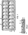
- Figure 1 is a top plane view for one embodiment of the diagnostic device.
- Figure 2 is a side view and cross section of the diagnostic device 10 of Fig.1 cut along the short axis.
- Figure 3 is a side view and cross section of the diagnostic device 10 of Fig. 1 cut along the long axis.
- Figure 4 shows a side view and cross section of a single well pair of diagnostic device 10 positioned for transfer under device 30.
- Figure 4a shows a side view and cross section of diagnostic device 10 positioned for transfer under device 30.
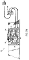
- Figure 5a shows an expanded top view of the device 30.
- Figure 5b shows a top view of the device 30.
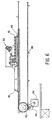
- Figure 6 shows the transport mechanism for moving device 10 under the transfer device 30.
- the present invention is directed toward an improved device for performing a solid-phase chemiluminescent immunoassay and methods for performing solid phase immunoassays with this device.
- the device is disposable and is suitable for manual use or for use with an apparatus having programmed instructions and means for adding sample and reagents, injecting a wash solution to transfer an assay reaction mixture to a read well and for optically reading the results of the assay.
- the device is designed to be employed in a variety of solid-phase diagnostic assay formats such as sandwich or competitive binding assays.
- the device is also designed so that it can be used for fluorescence or colorimetric detection methods.
- a special feature is preferably designed into this device to allow light tight seal for chemiluminescence measurements.
- the device of the present invention can be used for separating the immunochemical reaction products by immobilizing the products on a fibrous matrix through an interactive property between the fibrous matrix and the reaction product, such as through particulate reactants (microparticle capture methods) or through hydrophilic-hydrophilic binding interaction, ionic binding interactions, and the like (ion capture methods).
- Samples which can be assayed by the device include biological fluids such as whole blood, spinal fluid, urine, serum, and plasma. It is also envisioned that other fluid samples of a non-biological nature can be analyzed using the disposable device.
- the device is preferably molded to have sets of wells, each set comprises a shallow incubation well for receiving a sample which communicates through a sloping passage means with a read well for detecting the results of the assay procedure.
- the device is molded of opaque polystyrene, acrylonitrile-butadiene-styrene ter-polymer (ABS), polycarbonate, polyacrylates, HIPS or some other moldable material which is inert to the assay components.
- ABS acrylonitrile-butadiene-styrene ter-polymer
- the sample is placed either manually or mechanically into the shallow incubation well and reacted (hereinafter described) and after an appropriate time transferred and washed into the read well where the results of the assay are monitored or detected.
- each read well 14 has a holding means 20, a fibrous material 22 assembled into a square or a rectangular array.
- Each read well element has a separate fibrous matrix 22 and either a separate absorbent material element 24 or a common absorbent material pad or layers of absorbent material pads. It can also be assembled in such a way that individual absorbent material elements 24 are in intimate contact with the fibrous matrix 22 on one end and with a common absorbent layer on the other end. Any of the absorbant material configurations is chosen to enhance diffusion of fluids away from the fibrous matrix 22. For high throughput instruments, the array assembly is preferred.
- the surface feature 26 is an array of rectangular ribs wherein each rectangle encloses an incubation well/read well pair and acts as a light seal when a chemiluminescence detector, with matching groove padded with compressible polymeric material, mates with it.
- Vent hole 28 is associated with each incubation well/read well pair. It vents out the air originally entrapped in the absorbant pad and is displaced by reaction mixture and transfer and wash solutions. Intimate contact between the fibrous matrix 22 and the absorbent material 24 is assured by compressing the absorbent material against the fibrous matrix using surface features 25 on the internal bottom surface of the disposable device 10.
- Shallow incubation well 12 can be semi-spherical, semi-cylindrical, toroidal or any complex curvature with no sharp corners.
- the largest radius of curvature of the shallow incubation well is along the axis connecting the incubation well to the read well.
- Dimensions of the shallow Incubation well 12 are chosen to maximize the volume of reaction mixture that can be incubated in the well, without having a steep fluid angle.
- a high fluid exit angle requires high wash solution injection speeds. Under these conditions fluids from incubation wells may overshoot the read well as they are transferred. On the other hand low exit angles may lead to self transfer or spilling of reaction mixture into the read well. Choice of dimensions and their relationship to fluid properties can be easily calculated by those skilled in the art.
- Transfer takes place by injecting wash fluid at the side of the shallow incubation well 12, farthest from the read well 14 using a transfer device 30 shown in Figure 4.
- a group of nozzles 32 are positioned close to the surface of each incubation well 12 to inject transfer or wash solutions. Said solutions are injected into the shallow incubation well 12 at a small angle to the tangent to the surface of the well at its region of intersection with the meniscus of the reaction mixture. Angle between direction of solution injection and tangent to shallow incubation well surface are generally kept below 45°. Angles between 5° and 20° are preferred.
- Transfer solution injection volumes and speeds at which it is injected into the shallow incubation well 12 depend on the reaction mixture volume needed to be transferred. Slow transfer solution injection speeds into the shallow incubation well 12 may lead to a partial transfer and successive dilution of reaction mixture. Then larger transfer solution volumes will be required to complete the transfer, which in turn necessitates a larger capacity of absorbent material 24 and hence a larger size disposable. Alternatively, the use of high transfer solution injection speeds may cause the reaction mixture to overshoot read well 14 and may cause the reaction mixture to splash back towards the injectors and contaminate them. In other words, depth and curvature of shallow incubation well 12, angle of exit port 16 and volume and injection speed of wash solution are dependent on the total assay volume to be incubated in well 12. Total assay volume in turn is optimized to achieve the desired binding reaction under the constraints of assay conditions. Those who are skilled in the art of fluid dynamics can calculate and optimize these dimensions once the essence of this invention is understood.
- the read well 14 generally comprises a sloping down entrance port and holding means 20, a fibrous matrix 22, and an absorbent material 24.
- the entrance port and holding means 20 can be a molded portion of the device and preferably constitute a funnel-like structure which is an integral part of the incubation well 14.
- the holding means 20 is designed with sloping sides which contact the upper surface of the fibrous matrix 22 and is sized to hold a sufficient amount of sample, conjugate material or other reagents to satisfy the requirements of the particular assay being performed.
- the holding means 20 should be sufficiently opaque, preferably made of black plastic material, to decrease background interference with the optics system.
- Each pair of incubation and read wells is preferably surrounded by a raised portion, preferably in the form of a rib or a thin plastic wall 26 which is a molded feature of the disposable device and acts as a mating part for another feature on a chemiluminescence reader to create a light tight seal.
- the height of such light seal is preferably between about 0.5 mm (0.020 inches) and about 2.5 mm (0.10 inches), and more preferably between about 1 mm (0.04 inches) and about 2 mm (0.08 inches).
- the transfer device 30 comprises two groups of nozzles 32.
- Each group of nozzles is directed towards an incubation well of the reaction tray 10 that has two rows of incubation well/read well pairs.
- Each group of nozzles is connected to fluid distribution manifold 34 into which transfer or wash solutions are injected via a stepper motor controlled pump.
- the first set of nozzles is directed towards the first incubation well of the plurality of well pairs and the second set of nozzles is directed into the second parallel incubation well and fluid flow is diverted to the second set of nozzles via a valve 36 using the same pump.
- an independent pump can be used for each set of nozzles.
- the transfer process can be performed on two parallel incubation wells either sequentially or simultaneously.
- a single pulse or several pulses of transfer solution are injected into the incubation well with a delay time between injections to allow the transferred fluids to drain from the read well 14. This prevents splashing and back washing of the reaction mixture from the read well into the incubation well, an action that can reduce transfer efficiency. Drainage time between fluid transfers is preferably within the range of about 2 to about 180 seconds, more preferably between about 2 to about 60 seconds and most preferably between about 2 to about 15 seconds.
- wash solution may be injected into the incubation well in a manner similar to the transfer solution to wash any capture agent analyte/conjugate complex on the walls of the retaining means 20 into the fibrous matrix 22 or to wash the unretained portions of the reaction mixture from the fibrous matrix 22.
- each nozzle is connected to a pump either directly or via a valve and can be used to deliver a reagent to the transferred and washed reaction mixture on the fibrous matrix 22.
- a pump either directly or via a valve and can be used to deliver a reagent to the transferred and washed reaction mixture on the fibrous matrix 22.
- One such nozzle can be used for adding additional wash solution into the read well to transfer any capture agent analyte/conjugate complex on the walls of the retaining means 20 into the fibrous matrix 22 where it is retained and immobilized. This in turn decreases fluctuations in assay numbers due to varied amounts of retained immune complex.
- the same nozzle can be used to wet the fibrous matrix with wash solution before transfer to improve fluid flow into the matrix and the absorbent material.
- Another nozzle can be used for adding a second reagent to the transferred reaction mixture on the fibrous matrix 22.
- the transfer and wash solutions preferably contain a small amount of detergent in order to decrease the surface tension and improve wetting the plastic and facilitate transfer.
- Detergents such as Tween®, sodium dodecyl sulfate or lithium dodecyl sulfate can be used for this purpose.
- Other surface active agents can be contemplated and used by those skilled in the art.
- An alternate way to transfer reaction mixture from shallow incubation well 12 into read well 14 is to use a combination of air and wash solution nozzles.
- alternating wash solution nozzles and compressed air nozzles in a group of nozzles directed towards the wall of each shallow incubation well 12 and simultaneously activating them can affect the same transfer described previously. This saves in the fluid volume used in the assay and hence in the volume of fluids to be disposed of in the absorbent material 24.
- the transfer device 30 can be moved by robotic means and accurately positioned on subsequent incubation wells to affect transfer and wash of the reaction mixture.
- a preferred way to bring new wells under the transfer device 30 is to move the disposable device 10 in a controlled manner under the transfer device 30 using a mechanism 40, comprised of a timing belt 42 controlled by a stepper motor 44 and gear reduction system 45.
- a rectangular plastic lug 46 pushes the disposable device 10 to new positions.
- Other means of moving the disposable device such as the use of linear actuators, metal belts or screw drives can be contemplated and used by those skilled in the art.
- the fibrous matrix 22 is a thin disk-like porous material positioned below the entrance port and holding means 20 to retain and immobilize a complex from which an assay signal can be read.
- the phrase "retain and immobilize” means that the captured/labeled immune complexes while upon the fibers of the material are not capable of substantial movement to positions elsewhere within the material, (i.e., to other fibers), and cannot be readily removed completely from the material.
- the pore size, particle retention size or spatial separation of the fibers comprising the fibrous matrix 22 is essential to the overall performance of the solid-phase immunoassay contemplated by the present invention. It must allow adequate void areas to assure the proper flow of reagents and sample through the fibrous matrix. Preferably, the spatial separation of the fibers must be larger than the diameter of the microparticles employed in a microparticle capture assay such that after the microparticles are deposited on the fibrous matrix, the matrix is not blocked but instead remains porous.
- porous means that the matrix is and remains a material into which fluids can flow and can easily pass through without the need to apply vacuum or pressure to facilitate its flow.
- the fibrous matrix 22 may simply retain or filter a complex from which an assay signal can be read.
- the spatial separation of the fibers are smaller than the diameter of the microparticles employed in a microparticle capture assay, the quantity of microparticles deposited on the fibrous matrix must be controlled such that the matrix is not blocked but instead remains porous.
- the fibrous material of the present invention can be chosen from any of a variety of porous materials such as glass, cellulose, nylon or other natural or, synthetic fibrous material well known to those skilled in the art.
- a suitable material is H&V Product No. HC411 glass fiber filter paper, which has a nominal thickness of 1.4 mm (0.055 inches), a mean pore size determined by the bubble point method of 4.1 ⁇ m with a particle retention size filtration range of about 2.6 to about 11 ⁇ m and a 98% capture efficiency for latex microparticles having a diameter of 1.2 ⁇ m (commercially available from Hollingsworth and Vose Co., West Groton, Massachusetts).
- the "particle retention size" of a depth filter refers to the size of particle that a particular grade of filter will effectively retain. There is no fixed relationship between the particle retention size of a porous material and the pore size of a porous material. However, the particle retention size is affected by the thickness of the material. The thickness of the porous material is a matter of choice largely based upon the properties of the sample being assayed, such as fluidity. Once a particular particle size is selected, the porous material of the present device would be selected according to the particle retention size and the fluid properties of the sample. Preferably, the porous material of the present device will retain the particles near the top surface of the porous material without substantially affecting the flow rate of the reaction mixture through the porous material into the absorbent material.
- the fibrous matrix 22 is positioned against the holding means 20 and above a means that functions to facilitate the transportation of fluid through the fibrous matrix.
- This is an absorbent element made of any moisture or fluid-retaining material which effectively retains fluid passing through the fibrous matrix 22.
- An absorbent material 24 is positioned below the fibrous matrix 22 and is in intimate contact with the lower surface of fibrous matrix 22 in order to absorb any reagent that flows through the fibrous matrix. This contact assures rapid transportation of the reaction fluids through the fibrous matrix 22.
- the microparticles employed to perform the solid-phase immunoassay are selected to have an average size that is preferably small enough such that they are suspendable in water or a sucrose solution to facilitate their coating with an antibody or antigen.
- the average individual size of the microparticles which is small enough to both be suspendable in solution and retained and immobilized in the fibrous matrix, is from about 0.1 to about 50 ⁇ m, more preferably from about 1 to about 10 ⁇ m in diameter.
- the microparticles can be selected from any suitable type of particulate material such as polystyrene, polymethylacrylate, polypropylene, latex, polytetrafluoroethylene, polyacrylonitrile, polycarbonate or similar materials.
- Uncoated microparticles can be employed for binding some analytes but in many situations the particles are coated with a substance for binding an analyte, e.g., antibody or antigen, or a combination thereof.
- a substance for binding an analyte e.g., antibody or antigen, or a combination thereof.
- Robotic arms can supply the necessary reagents by various transferring means communicating with reagent containers located external to the device and associated mechanisms.
- an instrument mechanism or robotic means can position a pipetting or jet means for directing a stream of wash solution into the shallow incubation well 12.
- the assay device 10 can be placed on a conveyor where a timing belt can move it at precise time intervals to locations under automated pipettors, reagent dispensers, transfer devices, washing devices or detectors. Whether a linear or circular motion is used to move the disposable, it is ultimately brought under a transfer device which successively injects transfer fluid into well 12 to wash the assay reaction mixture through passage means 16, into the read well 14.
- This particular feature of the device 10 prevents contamination of the automated apparatus or pipetting means as well as the assay reaction mixture. Also, a pipette never needs to be washed to prevent cross contamination of other assays.
- a sample is added to the shallow incubation well and the device is placed on a transport means designed to hold a plurality of devices.
- Steps (a) through (e) may be performed by a microprocessor-controlled automated instrument or manually as follows:
- steps (a) and (b), i.e., formation of analyte/conjugate complex and formation of microparticle analyte/conjugate complex, respectively, can be performed simultaneously by adding the capture agent, sample and analyte-specific conjugate to the shallow incubation well and incubated. The complex is then washed into the read well.
- detection of the signal produced in the read well varies with the type of label used.
- a substrate solution is added in the read well and the product formed is detected by color development or generation of a fluorescent signal.
- fluorophore labeled antigen or antibodies direct excitation of fluorophore and detection of spontaneous or time resolved fluorescence signal is used.
- chemiluminescent labeled antigens or antibodies detection is achieved by chemically activating the luminescent label and monitoring generated light. In all these methods of detection, either the total integrated signal over a period of time or the rate of change of signal over the observation period can be used to establish a standard curve for the assay and determine the concentration of analyte in unknown samples.
- the transportation step (c) can be performed either before or after the addition of the analyte specific conjugate to the microparticle analyte complex, i.e., either the microparticle analyte complex is transferred and then the analyte specific conjugate is added to the read well, or the analyte specific conjugate is added to the microparticle and analyte mixture in the incubation well and the resulting microparticle analyte/conjugate complex is then transferred to the read well.
- the disposable device can be employed to perform a competitive binding assay.
- the automated or manual steps are as follows:
- the present invention is directed toward the device described above and the method of transfer, and in a preferred embodiment to the device which is suitable for the automated performance of a solid-phase immunoassay process on a microprocessor-controlled automated instrument.
- This method of incubation in one compartment, fluid transfer, separation and signal generation in another compartment described in this invention is not limited to microparticle based immunoassays.
- another preferred embodiment of the invention is to use an ion capture separation method as described above.
- the different procedures and examples described above for the use of microparticles as a capture phase can be used with ion capture, where a polyanionic material attached to a hapten, antigen or antibody is used as a capture agent in place of the microparticles in each example. After transfer of the polyanionic material to the positively charged glass fiber matrix, the immune complex is retained and immobilized on the glass fiber matrix by ionic forces.
- Chemiluminescent moieties can be used as probes or labels in a specific binding assay.
- chemiluminescent labels such as acridinium sulfonamides
- an activator or activating reagent such as alkaline peroxide
- an enzyme label such as alkaline phosphatase
- a catalyst to generate light from a chemiluminescent substrate, such as a dioxetane aryl phosphate substrate.
- Acridinium sulfonamides labeling chemistry may be employed according to the present invention for making a stable chemiluminescent tracer of high quantum yield.
- Alkaline phosphatase labeling techniques known in the art and use of dioxetane catalyzed chemiluminescence may be also used according to the present invention to generate a long-lived signal that can be integrated to yield high sensitivity assays.
- One such assay for Hepatitis B Surface antigen has sensitivities which exceed those of other methods.
- one such type chemiluminescence immunoassay for Hepatitis B surface antigen ( Cin. Chem, 27, 1378-1384 (1981)) involves two incubation periods, 1.5 hours each, and has a lower limit of detection of 2 ng/ml A lower limit of detection of 1 ng/ml is achieved by increasing the incubation time to 16 hours.
- sub-nanogram quantities of Hepatitis B surface antigen may be detected within a total assay time of about one hour.
- a sandwich immunoassay is performed employing either a microparticle or a polyanionic acid, such as polyglutamic acid, which is attached to an antibody or to the analyte under determination, and added to a reaction vessel, either simultaneously or sequentially, with the analyte from the test sample and a chemiluminescent-labeled antibody.
- the reaction mixture is incubated for a period of time and under conditions which maximize the specific binding reaction.
- the reaction mixture is then transferred to the read well. Transfer of the reaction mixture into the read well of the two well device described above and shown in Figure 1 can be achieved by a non-contact hydraulic or fluidic means such as described by EP-A-0 424 633.
- transfer of the reaction mixture into the read well can be achieved by mechanical means such as a manual or automated pipettor.
- the chemiluminescence signal from acridinium labeled assays is triggered and simultaneously detected on the fibrous matrix in the light-tight compartment formed from the disposable device and a detector head such as the detector head described in US Patent 5,089,424
- the signal is integrated over a period of time longer than the sum of the rise and decay times of the chemiluminescence signal, but shorter than the residence time of the triggered reaction mixture in the fibrous matrix.
- a sandwich immunoassay is performed employing a polyanionic acid such as polyglutamic acid which is attached to an antibody or to the analyte under determination, and added to a reaction vessel, either simultaneously or sequentially, with the analyte from the test sample and an enzyme-labeled antibody.
- a polyanionic acid such as polyglutamic acid
- Alkaline phosphatase or ⁇ -galactosidase-labeled antibody or antigen may be used.
- the reaction mixture is incubated for a period of time and under conditions which maximize the specific binding reaction.
- the reaction mixture is similarly transferred to a separation and detection chamber as described above.
- a long-lived chemiluminescent signal generating indicator may be added thereto to generate a chemiluminescent signal from the fibrous matrix in the separation and detection chamber before the device is mated with the detector head to form a light-tight compartment where the chemiluminescence signal is detected.
- the signal is integrated over a period of time longer than the sum of the rise and decay times of the chemiluminescence signal, but shorter than the residence time of the triggered reaction mixture in the fibrous matrix.
- competitive immunoassays using such chemiluminescent labeled antigen, antibody or other binding protein, or fragments thereof can also be prepared and used in the present invention.
- the device of the present invention may also be utilized with other assay methods, such as amplified heterogeneous chemiluminescent immunoassay methods described in WO 92/08979, which utilize antigen coated microparticles, antigen-biotin conjugates and chemiluminescent compound labeled anti-biotin antibody to detect the presence or amount of anti-antigen antibody in a sample.
- incubation and separation steps take place in two independent compartments.
- the amount of sample and labeled conjugate that binds non-specifically to the fibrous matrix and wall of separation and detection compartment is. substantially reduced as compared to incubation, wash and detection in the same well as described in U.S. Patent No. 4,652,533, in J. Immuno. Methods, 67, 21-35 (1984), or Clin. Chem., 32, 1682-1686 (1986), and accordingly,results in improved assay sensitivity.
- Acridinium sulfonamide or ester labels are triggered by the addition of an alkaline peroxide solution to produce a short lived chemiluminescence signal. Because such chemiluminescence signals are short-lived, the activation of the chemiluminescent label is affected within a light-tight compartment, preferably created by mating the detector head with the disposable device. Long-lived dioxetane-type chemiluminescence is generated by adding an enzyme specific chemiluminescent substrate to the enzyme-labeled immune complex on the fibrous matrix.
- alkaline phosphatase substrate 3-(2'-spiroadamantane)-4-methoxy-4-(3''-phosphoroxy)phenyl-1,2-dioxetane disodium salt (AMPPD) from Tropex Inc., Bedford, MA.
- AMPPD alkaline phosphatase substrate 3-(2'-spiroadamantane)-4-methoxy-4-(3''-phosphoroxy)phenyl-1,2-dioxetane disodium salt
- AMPPD alkaline phosphatase substrate 3-(2'-spiroadamantane)-4-methoxy-4-(3''-phosphoroxy)phenyl-1,2-dioxetane disodium salt
- the enzyme substrate can be incubated before the disposable device engages the detector head and start of signal integration.
- the hydrogen peroxide concentration in the alkaline peroxide solution used to trigger the chemiluminescent reaction on the fibrous matrix is kept within a range of about 0.1 to about 1.0 percent by volume in a sodium hydroxide solution having a concentration within the range of about 0.1 to about 0.25 N.
- a preferred concentration is about 0.3% hydrogen peroxide solution in about 0.25 N sodium hydroxide solution.
- chemiluminescent reactions in solution are triggered with alkaline hydrogen peroxide containing approximately 0.03% by volume hydrogen peroxide in 0.1-0.25 N sodium hydroxide solution. Higher concentrations of the trigger solution generate higher signal in a short period of time, possibly before triggered reaction mixture diffuses through the fibrous matrix.
- the absorbent material typically cellulose acetate, commercially available from American Filtrona Company, Richmond, VA
- the absorbent material typically cellulose acetate, commercially available from American Filtrona Company, Richmond, VA
- the observed chemiluminescence intensity varied between different manufacturing lots of the absorbent material and its contribution to the total signal could not be readily accounted for in the assay chemiluminescent signal.
- the inventors also observed chemiluminescence in neighboring wells of the device shown in Figure 1, which was apparently a result of light leakage through the absorbent material from adjacent wells. Such background chemiluminescence reduces the sensitivity, accuracy and precision of an assay.
- Light absorbing material means porous material pigmented or colored other than white having properties such that the quantum of measurable chemiluminescence generated in or capable of passing through the pigmented porous material is substantially less than the quantum of measurable chemiluminescence generated in or capable of passing through white or non-pigmented porous material composed of the same material.
- Cellulose acetate fiber material containing carbon black preferably Transorb® Reservoir, black (commercially available from American Filtrona Company, Richmond, VA, and prepared from Eastman Estron® acetate tow, filtration grade, X-shaped fiber, No. 40, cross-section 5.0, Dernier/filament total 40,000) was effective in substantially reducing background chemiluminescence in the absorbent pad of the read well and is a preferred light absorbing material useful in the present invention.
- Black polycarbonate absorbent materials may be an alternative light absorbing material useful in the present invention.
- Polycarbonate absorbent materials can be rendered black with Irgalan black (Color Index, acid black 107) by soaking the material in a solution of Irgalan black in 2% acetic acid (2g/l) for 24 hours, washing with water and drying at room temperature or at 82°C for fifteen minutes.
- Irgalan black Color Index, acid black 107
- 2% acetic acid 2g/l
- One skilled in the art can readily conceive of other materials having such light absorbing properties which can be used.
- a layer of light absorbing material may be placed between the fibrous material and the absorbent pad, such that the reaction mixture may pass through the light absorbing layer into the absorbent pad but substantially reducing the quantum of chemiluminescent light produced in the absorbent layer which reaches the detector above the fibrous matrix.
- the black cellulose acetate fiber material may be used as the absorbent pad of the read well or may be used as a light barrier between the absorbent pad and the fibrous matrix of the read well. In the latter case, the required thickness or quantity of black cellulose acetate fiber used as a light barrier would be substantially less than the required thickness or quantity of black cellulose acetate fiber required for use as an absorbent pad, because the absorbent pad has the added function of absorbing liquid from the read well.
- the layer of light absorbing material may be a black mesh material (a fine synthetic fiber mesh), such as black colored nylon (polyamide) #PA 120/44 (commercially available from Saati Corporation, Industrial Fabrics Division, Stamford, Connecticut) which has a mesh opening of 120 ⁇ m, a mesh count of 55 threads per centimeter (140 threads per inch), a thread diameter of 61 ⁇ m and a thickness of 110 ⁇ m.
- black mesh material a fine synthetic fiber mesh
- the absorbent pad may be constructed in layers of white absorbent material, such as cellulose acetate, and black cellulose acetate so long as the top layer adjacent to the fibrous matrix is the black cellulose acetate layer.
- the inventors further discovered an additional advantage to utilizing such light absorbing material in the present device.
- the light absorbing layer also reduces extraneous light from reaching the detector through the bottom or sides of the device.
- the bottom and sides of the device need not be light-tight in order to form a light-tight seal between the device and the detector head.
- binderless fibrous material surprisingly further improves the sensitivity of assays performed with the device.
- the inventors discovered that the use of binderless fibrous material resulted in reduced chemiluminescent signal in assays of samples containing none of the analyte of interest (negative samples) and increased chemiluminescent signal in assays of samples containing the analyte of interest (positive samples).
- Binderless fibrous material can be chosen from any of a variety of materials such as glass, cellulose, nylon or other natural or synthetic fibrous material well known to those skilled in the art wherein such materials are formed without the aid of binder.
- a suitable material is binderless glass fiber filter paper, which has a nominal thickness of about 1.4 mm (0.055 inches).
- a preferable binderless fibrous material is #F315-03 unbound glass grade having a mean pore size by the bubble point method of about 4 ⁇ m with a particle retention size filtration range of about 3 to about 10 ⁇ m and a 98% capture efficiency for latex microparticles having a diameter within the range of about 1.2 to about 1.4 ⁇ m (commercially available from Whatman Paper Ltd., Specialty Products Division, Springfield Mill, Maidstone, Kent ME142LE, England).
- the thickness of such material is not critical, and is a matter of choice for one skilled in the art, largely based upon the properties of the sample being assayed, such as fluidity.
- the pore size or spatial separation of the fibers must allow adequate void areas to assure the proper flow of reagents and sample through the fibrous matrix.
- a disposable reaction tray was constructed according to the embodiments of this invention as described hereinabove from two injection molded parts.
- the disposable tray was 17.3 cm (6.800 inches) long, 7.9 cm (3.125 inches) wide, and 2.0 cm (0.800 inches) high.
- the top part incorporated a two by eight rectangular array of the shallow incubation wells. Associated with each incubation well was the funnel-like structure (read well) and the passage way between them described hereinabove.
- the capacity of the incubation well was 280 microliters and the capacity of the funnel was 480 microliters.
- the center to center spacing of the two adjacent incubation wells or two adjacent funnels was 1.4173 inches (36 mm).
- the pitch of the rows of consecutive wells was 2.0 cm (0.800 inches).
- the funnel like structure has a cutting edge on the inside surface.
- the height of the surface feature for light sealing was 1 mm (0.040 inches) and its width was 1 mm (0.040 inches).
- the vent hole was located 6.4 mm (0.250 inches) from the edge of the light baffle and was 1.5 mm (0.060 inches) in diameter.
- the top part was injection molded of black ABS.
- the bottom part was an injection molded piece of white ABS which mates with the top part and was sonically welded to it.
- the top and bottom parts had surface features to fix a slab of absorbant material in place.
- the top part of the disposable device was turned upside down and a sheet of fibrous glass was placed inside the disposable, covering the bottom part of the read wells. The fibrous material was pressed against the cutting edges of, the bottom of the funnel-like structures to cut individual filter matricies for each well.
- the over-all diameter of each matrix was 8.9 mm (0.350 inches).
- the absorbant material was placed in the top part of the disposable in contact with the glass fiber matricies. It was a rectangular slab 16.5 cm (6.5 inches) long, 7.6 cm (3 inches) wide and 6.7 mm (0.265 inches) thick.
- the material was bonded cellulose acetate, Transorb® Reservior, white (commercially available from the American Filtrona Company, Richmond, Virginia, and prepared from cellulose acetate tow from Hoechst-Celanese).
- the absorbant pad was pressed against the glass fiber matricies by the bottom part.
- the surface features on the bottom part was in the form of a group of rings, each ring was concentric with one of the funnel-like structures and had a diameter of 16.9 mm (0.665 inches) with a rib 3.0 mm (0.120 inches) high.
- the preferred design ring pushed the pad of absorbant material against the glass fibrous matrix and assured intimate contact between the two layers.
- the two parts were assembled and welded using a Branson ultrasonic welder, Branson Ultrasonics, Danberry, CT, with a horn optimized to fit the disposable device.
- a transfer device similar to that described in the embodiments of this invention was constructed. Sample and reagents were incubated in the shallow incubation well. Transfer solution was injected from an group of three adjacent nozzles 0.5 mm nominal inside diameter made of Teflon® tubing and connected to a machined polyacrylic manifold by minstac fittings from the Lee Company, Westbrook, CT. The manifold was connected through a solenoid activated three way valve (Angar Scientific, Florham Park, New Jersey) to a stepper motor controlled syringe pump. The nozzles were directed at an angle of 13° to the tangent to the shallow well surface at its point of intersection with reaction mixture surface. In this geometry the nozzles were at a 60° angle to the horizontal plane.
- Transfer solution was injected in the manifold at the rate of 1250 ⁇ l per second.
- the average linear injection speed was 2.1 m/second.
- the exit angle of fluid was 28°.
- Two aliquots 300 ⁇ l each of transfer solution were injected into the incubation well to affect transfer.
- a delay time of 10 seconds was allowed between the two injections to allow for the fluids to drain through the fibrous matrix.
- the capacity of the funnel was sufficient to prevent wash back.
- Transfer solutions preferably contained an amount of detergent such as 0.025-0.1% Tween®20, 0.025-0.1 % sodium lauryl sulfate or lithium lauryl sulfate to prevent beading of fluids in the incubation well and facilitate fluid transfer.
- Three additional nozzles were installed in the transfer device and centered on the fibrous matrix. They were used either in groups or independently to wash the reaction mixture off the walls of the funnel into the matrix with a wash solution or to deliver conjugate solution to the matrix.
- the method of transfer and the function of the transfer device was tested by determining the efficiency of transfer of labeled chemiluminescent microparticles from the incubation well to the read well of the disposable device of Example 1, using the following method:
- Acridinium sulfonamide labeled antibody to Hepatitis B core antigen at a concentration of about 5 ⁇ g/ml was diluted in conjugate diluent, containing 50% fetal calf serum, 2% human plasma, 0.1% Tween®-20, 0.1% ethylenediaminetetraacetic acid and 0.1% sodium azide in phosphate buffered saline, pH 6.8, to a final conjugate concentration of about 150 ng/ml.
- Carboxylated polystyrene microparticles coupled to antibody to Hepatitis B core antigen as an undercoat and then with recombinant Hepatitis B core antigen were pooled from lots prepared for clinical trials and contained 0.3% solids by weight. Microparticles were suspended in phosphate buffered saline, pH 7.2, containing 16% sucrose. A 0.1% solution of Tween®-20 in phosphate buffered saline, pH 7.2, was used as a transfer solution.
- Luminescent microparticles for the determination of transfer efficiency were prepared by mixing 50 ml of conjugate solution and 50 ml of microparticles suspension. The reaction mixture was incubated in a water bath at 40°C for two hours. It was then left standing at room temperature for 24 hours to ensure complete binding of acridinium sulfonamide labeled antibodies to the antigen labeled microparticles.
- the disposable tray was nearly moved to a subsequent position where the transferred microparticles on the matricies were triggered using 0.3% alkaline peroxide solution.
- Trigger solution was prepared by dissolving peroxide in 0.25 M sodium hydroxide to yield an effective peroxide concentration of about 0.3%.
- the resulting chemiluminescence was measured using a detector head.
- Each side or row of well pairs (Side A and Side B, each side having 8 well pairs) of the disposable reaction tray was detected by an independent photomultiplier tube.
- the measured signal for each well was considered to correspond to the amount of the reaction mixture transferred from the incubation well to the read well.
- the mean and standard deviation for the eight wells on each side of the disposable were calculated.
- a base line was determined by dispensing 100 ⁇ l of luminescent microparticles onto the fiber glass matrix in each of the 16 read wells of a disposable reaction tray of Example 1 and the microparticle solution was allowed to drain through. 100 ⁇ l of fetal calf serum and 100 ⁇ l of de-ionized water were dispensed in each of the shallow incubation wells of the same disposable.
- the disposable reaction tray was placed on a linear track and moved to a position where it was located under a transfer device of the present invention.
- the efficiency of transfer was calculated by dividing the magnitude of the mean signal generated from the transferred microparticles on each side by the signal representing 100% transfer on a corresponding side.
- Precision of transfer of the reaction mixture from the incubation well to the read well was determined by repeating each of the two previously described transfer and base-line experiments on three disposable trays. The mean percent transfer and the %CV of the percent transfer were calculated for each side of the three trays. The experiments were repeated for six independent transfer devices mounted on six incubation tunnels. Each incubation tunnel was equipped with a read head and associated electronics controlled by an 310 development system (Intel corporation, Sunnyvale, CA). In all instances the transfer efficiency was higher than 95% and the %CV of transfer was well below 5%.
- Carboxylated polystyrene microparticles were coupled to anti-Hepatitis B core antigen antibody (HBc antibody) and then the HBc antibody particles were incubated with recombinant Hepatitis B core antigen and washed.
- HBc coated microparticles were suspended (about 0.3% solids by weight) in phosphate buffered saline, pH 7.2, containing 16% sucrose.
- Trigger solution was prepared by dissolving peroxide in 0.25 M sodium hydroxide to yield effective peroxide concentration of about 0.3%.
- HBc antibody negative controls and HBc antibody positive controls from a commercial enzyme immunoassay kit that has 50-60% inhibition as measured by a commercial enzyme immunoassay procedure (Corezyme Abbott Laboratories, North Chicago, IL) were used in the following two procedures:
- control or sample 100 ⁇ l of control or sample were dispensed into the shallow incubation wells of the disposable device of Example 1. Then 50 ⁇ l of acridinium labeled HBc antibodies and 50 ⁇ l of antigen coated latex particles were dispensed into the incubation wells.
- the reaction mixture was incubated for 40 minutes in a heated tunnel at 40°C with the disposable device moving into the tunnel by a stepper timing belt at steps of 2.0 cm (0.80 inches) per second per step. Mean time between each step, when the device is stationary, was about 72 seconds.
- the reaction mixture was transferred and then washed from the shallow incubation well onto the fibrous matrix of the read well. Transfer was accomplished by injecting two pulses of 300 ⁇ l each of the transfer solution into the incubation well from three nozzles in the transfer device. Each nozzle has a nominal diameter of 0.5 mm and the fluid was injected at an average linear speed of 2.1 m/second. A delay time of about 12 seconds was allowed between the two pulses to assure drainage of the transferred solution through the matrix.
- the disposable was moved on the timing belt to allow subsequent well pairs to be located under the transfer device and to transfer the reaction mixture and wash the microparticles retained and entrapped on the fibrous matrix.
- the disposable device 10 was moved at the same rate to a read position where a chemiluminescence detector head (described in US Patent 5,089,424) was lowered to mate with the walls surrounding the first two wells on the disposable to create a light-tight seal.
- the chemiluminescent labels on the microparticles on the fibrous matrix were triggered using the trigger solution.
- the measured signal for each well was considered to correspond to the amount of acridinium labeled conjugate attached to the microparticles.
- a % inhibition of 50% and higher was taken as positive and a % inhibition less than 50% was assigned as negative.
- control or sample 100 ⁇ l of control or sample were pipetted into the shallow incubation wells of the disposable device of Example 1. Then 50 ⁇ l of a solution of 50 mM cysteine, 10 mM EDTA and 0.01% gentamicin, and 50 ⁇ l of the antigen coated latex microparticles (see Materials above) were dispensed into each incubation well. The reaction mixture was incubated for 20 minutes in a heated tunnel at 40°C with the disposable device moving into the tunnel using the same mechanism described for the one step procedure. The reaction mixture was transferred from the shallow incubation well onto the fibrous matrix of the read well as described in the One Step Assay of this Example 3. A 12 second delay was allowed for the transfer solution to drain down into the absorbant pad.
- the disposable was moved on the timing belt to allow subsequent well pairs to be located under the transfer device and to affect transfer of the reaction mixture. 50 ⁇ l of the solution of acridinium labeled HBc antibodies were dispensed on each fibrous matrix of the read wells from one of the nozzles located in the transfer device and directed on the center of the read well. The disposable device was incubated for 20 more minutes in the tunnel using the same moving timing belt as it is moved to a washing position.
- the transferred microparticles, retained on the matrix in the read well, and the excess acridinium labeled antibodies were subsequently washed with three 100 ⁇ l aliquots, of wash solution.
- the disposable device was moved at the same rate to a read position where the chemiluminescent label on the microparticles on the fibrous matrix were triggered using the trigger solution and the chemiluminescence signal was integrated for six seconds.
- the measured signal for each well was considered to correspond to the amount of acridinium labeled conjugate attached to the microparticles
- This example shows the use of the device and method of this invention in a competitive binding assay for the abused drug phencyclidine (PCP) in urine employing ion capture immunoassay procedures described above.
- the formation of the immune complex in the shallow incubation well of the disposable device of Example 1 involves the use of an anionic polymer as part of the capture agent.
- the reaction mixture is transferred to the read well of said device and the immunochemical reaction product is immobilized by ionic forces on the fibrous matrix of said device that has been previously treated with a solution of a cationic polymer.
- Anti-phencyclidine antibodies were labeled with acridinium sulfonamide using EDAC coupling procedures.
- Pre-wet and transfer solutions were IMx® buffer (Abbott Laboratories, North Chicago, IL) containing 25 mM TRIS, 0.3 M sodium chloride, 0.1% sodium azide, pH 7.2.
- the cationic polymer was a 0.5% aqueous solution of CelquatTM L-200 (National Starch and Chemical Company; Bridgewater, NJ) in 10 mM sodium chloride.
- PCP-PGA phencyclidine-polyglutamic acid
- polyglutamic acid sodium salt Sigma Chemical Company, St. Louis, MO
- AG50W-X8 ion exchange resin Bio-Rad, Richmond, CA
- the liquor was separated and lyophilized to yield polyglutamic acid free acid (PGAFA).
- Phencyclidine-4-choroformate was prepared by reacting 1.4 mg 4-hydroxyphenylcyclidine in 0.5 ml tetrahydrofuran with 0.5 ml of 10% solution of phosgene in benzene (130 mole excess). The reaction was allowed to proceed for 2.5 hours at room temperature. Solvent was evaporated under a stream of nitrogen to yield a residue of phenylcyclidine-4-chloroformate. The residue was dissolved in 0.5 ml tetrahydrofuran and 1 .7 mg of free acid polyglutamic acid (molecular weight 40,000) in 0.5 ml 1-methyl-2-pyrrolidine was added. The reaction was stirred overnight at room temperature and then the reaction mixture was evaporated to dryness.
- the dried mixture was dissolved in 1.5 mL phosphate buffer, pH 7.0 and dialyzed against 0.1 M sodium phosphate at pH 7.0 in a 30,000 molecular weight cut-off dialysis bag.
- the precipitate was filtered and dissolved in phosphate buffer.
- the cloudy aqueous filtrate was extracted with methylene chloride until the aqueous layer was clear.
- the aqueous layer was diluted in a buffer containing 1% fish gelatin, 25 mM TRIS, 100 mM sodium chloride, 1 mM magnesium chloride, 0.1 mM zinc chloride and 0.1% sodium azide at pH 7.2 to yield 5 ⁇ g/l PCP-PGA capture reagent.
- Trigger solution was prepared by dissolving peroxide in 0.25 M sodium hydroxide to yield effective peroxide concentration of about 0.3%.
- Phencyclidine calibrators (TDxTM PCP FPIA Assay Kit, commercially available from Abbott Laboratories, North Chicago, IL) containing 500, 250, 120, 60, 25, and 0 ng/ml phencyclidine in human urine were assayed by the following procedure: a) 50 ⁇ l of pre-wet solution followed by 50 ⁇ l CelquatTM solution were dispensed on the fibrous glass matrix of disposable reaction tray of the present invention. b) 50 ⁇ l of control or sample were dispensed into the shallow incubation wells of the disposable device of Example 1. 50 ⁇ l of acridinium labeled anti-PCP antibodies were dispensed into each incubation well.
- the mixture was incubated for 9.8 minutes in a heated tunnel at 32°C with the disposable device moving into the tunnel by a timing belt in steps at the rate of 2.0 cm (0.8 inches) per minute. The mean time between steps was 36 seconds when the device remained stationary.
- 50 ⁇ l a solution containing PCP-PGA capture reagent was dispensed into the incubation well.
- the reaction mixture is further incubated for 9.8 minutes.
- the quaternary ammonium-polymer treated fibrous matrix was rinsed with 100 ⁇ l of IMx® buffer before the reaction mixture was transferred. c)
- the reaction mixture was transferred from the shallow incubation well onto the pretreated fibrous matrix in the read well.
- Transfer was affected by injecting a single pulse of 350 ⁇ l of IMx® buffer into the well at a speed of 1250 ⁇ l per second from the three nozzles in the transfer device.
- the disposable was moved on the timing belt to allow subsequent well pairs to be located under the transfer device and to affect transfer of the reaction mixture.
- a chemiluminescence detector head (described in US Patent TABLE 3 Ion-Capture Competitive Binding Assay For Phencyclidine (PCP) in Urine PCP [ng/ml] Side A Side B Signal % Bound Signal % Bound 0 199886 0.00 181430 0.00 25 33752 83.00 27753 85.50 60 12412 94.60 12140 94.19 120 6818 97.44 6106 97.54 250 3223 99.28 2907 99.32 500 1803 100.00 1690 100.00 5,089,424) was lowered to mate with the surface feature on the first two wells on the disposable to create a light-tight seal.
- the retained and immobilized immune complex on the matrix was triggered using the trigger solution and the signal was integrated for eight seconds.
- the measured signal for each well was considered to correspond to the amount of acridinium labeled conjugate attached to the fibrous matrix surface.
- the measured concentration of PCP below which a sample is considered negative is at 25 ng/ml.
- Microparticle-Based Sandwich CLIA For Hepatitis B Surface Antigen.
- AD subtype and AY subtype Hepatitis B Surface antigen (HBsAg) sensitivity panels AD subtype or AY subtype HBsAg purified from heat-inactivated HBsAg positive human serum spiked into HBsAg negative recalcified human plasma to predetermined concentrations
- positive and negative controls for HBsAg commercially available from Abbott Laboratories, North Chicago, Illinois
- An acridinium sulfonamide labeled goat anti-HBsAg polyclonal antibody conjugate was prepared and diluted to 0.17 ⁇ g/ml in conjugate diluent.
- Conjugate diluent was prepared by mixing 0.1 M monosodium phosphate, 0.1 M disodium phosphate, 0.1% sodium azide, 53% calf serum and 10% normal human serum. The conjugate diluent was filtered through 0.45 ⁇ m Nalgene disposable sterile filter (Nalge company, Division of Sybron Corporation, Rochester, NY) and then the diluent pH was adjusted to a final pH of 6.3. Finally, the diluent was filtered through a 0.2 ⁇ m Nalgene Filter.
- Trigger solution was prepared by dissolving peroxide in 0.25 M sodium hydroxide to yield effective peroxide concentration of about 0.3%.
- Carboxylated polystyrene microparticles (0.21 ⁇ m) were coupled to mouse IgM anti-HBsAg monoclonal antibodies using EDAC and a suspension of the microparticles was prepared with a total solids content of 0.24% (w/w).
- a wash solution was prepared containing 0.1 M borate, 0.02% lithium dodecyl sulfate, 0.9% sodium chloride and 0.1% sodium azide.
- control or sample 200 ⁇ l of control or sample were dispensed into the shallow incubation wells of a disposable tray described in Example 1. 30 ⁇ l of the microparticle solution were dispensed into the incubation wells.
- the reaction mixture was incubated for 20 minutes in a heated tunnel at 40°C with the disposable device moving into the tunnel by a stepper timing belt at step increments of 2.0 cm (0.8 inches) per second per step. Mean time between each step, when the device is stationary, was about 72 seconds.
- the reaction mixture was transferred from the shallow incubation well onto the fibrous matrix of read well using the method of Example 3 After the transfer solution drained down into the absorbant pad, 30 ⁇ l conjugate solution were dispensed onto each fibrous matrix.
- the disposable tray was incubated for 30 additional minutes in the tunnel using the same stepper timing belt and is moved to a washing position.
- the transferred microparticles that are retained on the glass fiber matrix and the added acridinium labeled antibodies were subsequently washed with three aliquots, 100 ⁇ l each, of wash solution containing 0.1 % sodium dodecyl sulfate, from a wash nozzle.
- the disposable tray is moved by the belt to a read' position where a chemiluminescence detector head (described in US Patent 5,089,424)
- a chemiluminescence detector head described in US Patent 5,089,424.
- the transferred and washed microparticles were triggered with the trigger solution.
- the measured signal for each well was considered to correspond to the amount of acridinium labeled conjugate attached to the microparticles and hence directly related to the concentration of the HBsAg in the sample.
- the results are summarized in Table 4.
- the standard deviation for twelve replicates of the negative control is 104.
- the cut off value (the value below which a sample is considered negative) of the assay was determined to be 2287 counts by adding 10 standard deviations to the mean of the negative control.
- concentrations of Hepatitis B Surface Antigen as low as 0.10 ng/ml of the AD subtype and 0.14 ng/mL of the AY subtype can be quantified using this microparticle capture chemiluminescence immunoassay.
- a limit of quantitation of Hepatitis B surface antigen one order of magnitude lower than reported in the art can be achieved.
- Example 1 The device of Example 1 was prepared utilizing white cellulose acetate absorbent material, Transorb® Reservoir, white (lot # P051410 and lot # I020192) or cellulose acetate absorbent material containing carbon black, Transorb® Reservoir, black (each commercially available from American Filtrona Company, Richmond, Virginia), but without the fiber matrix. Trigger solution was prepared by dissolving peroxide in 0.25 M sodium hydroxide to yield effective peroxide concentration of about 0.3%.
- Example 1 The device of Example 1 was prepared utilizing white cellulose acetate absorbent material, Transorb® Reservoir, white, or cellulose acetate absorbent material containing carbon black, Transorb® Reservoir, black (each commercially available from American Filtrona Company, Richmond, Virginia). Heat-inactivated HBsAg negative human recalcified plasma was spiked with HBsAg purified from heat-inactivated HBsAg positive human serum to a final concentration of 0 ng/ml (negative control), 0.5 ng/ml (low positive control) and greater than 5 ng/ml (high positive control) of HBsAg.
- Example 1 The device of Example 1 was prepared utilizing white cellulose acetate absorbent material, Transorb® Reservoir, white, or cellulose acetate absorbent material containing carbon black, Transorb® Reservoir, black (each commercially available from American Filtrona Company, Richmond, VA).
- AD subtype and AY subtype Hepatitis B Surface antigen (HBsAg) sensitivity panels AD subtype or AY subtype HBsAg purified from heat-inactivated HBsAg positive human serum spiked Table 7 HBsAg Assay Sensitivity Panel Data Sample Conc.
- the antibody was dialyzed against 0.1 M phosphate (pH 8.0), containing 0.15 M NaCl, and the protein then was adjusted to a concentration of 1 mg/ml in the same buffer.
- the activated acridinium derivative at a 5 to 10 molar excess then was added to the antibody solution at room temperature.
- the reaction mixture was centrifuged (12,000 rpm for two (2) minutes) to remove aggregates, and the supernatant solution then was applied to a TSK-250 gel filtration column, which previously had been equilibrated with 0.01 M sodium phosphate, pH 6.3, containing 0.15 M NaCl.
- One ml fractions were collected, and the absorbance monitored at 280 nm and 369 nm.
- HIV antigen (10 mg) in 34.28 ml of 0.5 M borate buffer (pH 8.5) is mixed with 10 ml of a 0.5% solids suspension of polystyrene latex particles, and then 55.72 ml of deionized water was added. The suspension was then allowed to stir overnight at room temperature. The solids were then isolated by centrifugation (17,000 rpm for 30 minutes) and then purified by three cycles of resuspension-centrifugation in 0.1 M phosphate buffer (pH 7.0) containing 0.1% Tween®. The coated particles were then resuspended, allowed to stir gently at 56°C for one (1) day, and then stored at room temperature prior to use.
- HIV antigen (1.9 mg) in 2.278 ml of 0.1 M borate buffer (pH 8.5), containing 250 mM NaCl and 0.1% sodium azide, was treated with 0.125 ml of 10% Triton® for 30 minutes. Then, 97 ⁇ l of 5 mg/ml of biotinamidocaproate N-hydroxysuccinamide ester dissolved in DMF, was added. The reaction mixture was allowed to stir at room temperature for about two (2) hours. The mixture was dialyzed extensively against 0.1 M borate buffer (pH 8.5) containing 250 mM NaCl, 0.1% SDS, and 0.1% sodium azide.
- the washed suspension then was allowed to incubate for about ten (10) minutes at 40°C before it was treated with 30 ⁇ l of 750 ng/ml solution of biotinylated HIV antigen in 0.1 M borate buffer (pH 8.5), 1% E. coli lysate, 500 ⁇ g/mL CKS, 12.5% calf serum, and 1.0% Cholic Acid containing 0.1% sodium azide.
- the capture membrane then was allowed to incubate for 20 minutes before it was washed with three (3) 100 ⁇ l portions of a pH 8.5 wash solution which comprised 0.1 M borate, 0.15 M NaCl, and 0.03% LDS containing 0.1% sodium azide.
- the washed capture membrane then was treated with 30 ⁇ l of a 167 ng/ml solution of the anti-biotin antibody coupled to acridinium sulfonamide in 0.01 M phosphate (pH 6.3), 0.15 M NaCl, 5% BSA, and 1.0 % Triton® containing 0.1% sodium azide. After a further ten (10) minute incubation at 40°C, the capture membrane was washed with five (5) 100 ⁇ l portions of a pH 8.5 solution of 0.1 M borate, 0.15 M NaCl and 0.01% LDS, containing 0.1% sodium azide.
- the washed capture membrane then was incubated for ten (10) minutes at 40°C prior to being treated with an alkaline peroxide solution (0.25 N NaOH containing 0.3% peroxide).
- the chemiluminescence was read for six (6) seconds and the presence or absence of anti-HIV was determined, as described in more detail in Example 9E hereinafter.
- Example 1 The device of Example 1 was prepared utilizing white cellulose acetate absorbent material, Transorb® Reservoir, white, or cellulose acetate absorbent material containing carbon black, Transorb® Reservoir, black (each commercially available from American Filtrona Company, Richmond, VA).
- Anti-HIV antibody negative recalcified human plasma (negative control) and heat-inactivated anti-HIV antibody positive recalcified human plasma spiked into negative control (positive control) were assayed for anti-HIV antibody according to the general procedure described in Example 9D using the trays containing white and black cellulose acetate absorbent material.
- Example 9D The general method described in Example 9D was modified only in the volume (30 ⁇ l or 50 ⁇ l) of the biotinylated HIV antigen ("probe") solution and/or the anti-biotin antibody coupled to acridinium sulfonamide (“conjugate”) solution used in the assay.
- probe biotinylated HIV antigen
- conjugate acridinium sulfonamide
- Each control was assayed in triplicate on each row (Side A or B) of each tray type using each combination of probe and conjugate solutions volumes as listed in Table 8.
- the resulting chemiluminescent signal generated in the assays on each tray was detected using a pair of the detectors described above. One detector read the wells on the left side of the tray (Side A) and one detector read the eight wells on the right side of the tray (Side B).
- Example 1 The device of Example 1 was prepared utilizing cellulose acetate absorbent material containing carbon black, Transorb® Reservoir, black (commercially available from American Filtrona Company, Richmond, VA) and either a fiber matrix of glass fiber containing binder (commercially available from Hollingsworth and Vose Co., West Groton, Massachusetts) or fiber matrix of glass fiber not containing binder (binderless) #F315-03 (commercially available from Whatman Paper Ltd., Specialty Products Division, Springfield Mill, Maidstone, Kent ME142LE, England).
- Heat-inactivated HBsAg negative human recalcified plasma was spiked with HBsAg purified from heat-inactivated HBsAg positive human serum to a final concentration of 0 ng/ml (negative control), 0.5 ng/ml (low positive control) and greater than 5 ng/ml (high positive control) of HBsAg.
- the controls were assayed for HBsAg according to the procedure described in Example 5 using the trays containing black cellulose acetate absorbent material and either glass fiber matrix with binder or glass fiber matrix without binder. The resulting chemiluminescent signal generated in the assays on each tray was detected using a pair of the detectors described above.
- Table 9 HBsAg Assay Using Matrix With And Without Binder Matrix With Binder Matrix Without Binder Side A Side A mean* SD** %CV mean* SD** %CV Neg.
- Example 1 The device of Example 1 was prepared utilizing cellulose acetate absorbent material containing carbon black, Transorb® Reservoir, black (commercially available from American Filtrona Company, Richmond, VA) and either a fiber matrix of glass fiber containing binder #AGC4111 (commercially available from Hollingsworth and Vose Co., West Groton, Massachusetts) or fiber matrix of glass fiber not containing binder (binderless) #F315-03 (commercially available from Whatman Paper Ltd., Specialty Products Division, Springfield Mill, Maidstone, Kent ME142LE, England).
- binder #AGC4111 commercially available from Hollingsworth and Vose Co., West Groton, Massachusetts
- binderless #F315-03 commercially available from Whatman Paper Ltd., Specialty Products Division, Springfield Mill, Maidstone, Kent ME142LE, England.
- HBc antibody negative controls and HBc antibody positive controls from a commercial enzyme immunoassay kit that has 50-60% inhibition as measured by a commercial enzyme immunoassay procedure were assayed for anti-HBc antibody according to the Two Step Competitive Assay Procedure described in Example 3B using the trays containing black cellulose acetate absorbent material and either glass fiber matrix with binder or glass fiber matrix without binder.
- the resulting chemiluminescent signal generated in the assays on each tray was detected using a pair of the detectors described above. One detector read the eight wells on the left side of the tray (Side A) and one detector read the eight wells on the right side of the tray (Side B).
- the binderless glass fiber matrix had not only substantially improved the sensitivity of the anti-HBc antibody assay by reducing background chemiluminescence, but also substantially enhanced the chemiluminescent signal generated in the assays of positive samples which significantly enhanced the signal-to-noise ratio (S/N).
- the device and method of this invention can be used to perform immunoassays for macromolecular antigens, viral and bacterial antigens and haptens. It can be extended to nucleic acid probes.
- chemiluminescence can be performed and detected using the device and method of this invention such as luminol type chemiluminescence or enzyme catalyzed dioxetane chemiluminescence.
- the device and method of this invention can be used with other detection methods and hence with other labels, such as front surface measurements using enzyme catalyzed substrate fluorescence or time resolved fluorescence, rare earth chelate labels or precipitated product immunoassays, and reflectance measurements.
Landscapes
- Health & Medical Sciences (AREA)
- Chemical & Material Sciences (AREA)
- Immunology (AREA)
- Life Sciences & Earth Sciences (AREA)
- Hematology (AREA)
- Engineering & Computer Science (AREA)
- General Health & Medical Sciences (AREA)
- Analytical Chemistry (AREA)
- Chemical Kinetics & Catalysis (AREA)
- Clinical Laboratory Science (AREA)
- Molecular Biology (AREA)
- Biomedical Technology (AREA)
- Urology & Nephrology (AREA)
- Cell Biology (AREA)
- Microbiology (AREA)
- Biotechnology (AREA)
- Food Science & Technology (AREA)
- Medicinal Chemistry (AREA)
- Physics & Mathematics (AREA)
- Biochemistry (AREA)
- General Physics & Mathematics (AREA)
- Pathology (AREA)
- Investigating Or Analysing Materials By The Use Of Chemical Reactions (AREA)
- Solid-Sorbent Or Filter-Aiding Compositions (AREA)
- Automatic Analysis And Handling Materials Therefor (AREA)
Abstract
Claims (7)
- Appareil de diagnostic destiné à être utilisé pour des analyses immunologiques par chimioluminescence, comprenant :a) une cellule (14),b) une ouverture formée dans la cellule,c) un patin absorbant (24) placé près de l'ouverture,d) un élément associé au patin absorbant et destiné à réduire la lumière transmise à partir du patin absorbant, ete) un liant fibreux (22) placé entre l'ouverture formée dans la cellule et le patin absorbant.
- Appareil de diagnostic pour analyse selon la revendication 1, dans lequel l'élément (d) est un pigment.
- Appareil de diagnostic pour analyse selon la revendication 2, dans lequel le pigment a une absorption de la lumière supérieure à celle d'un matériau blanc.
- Appareil de diagnostic pour analyse selon la revendication 2, caractérisé en ce que le pigment est au moins un élément choisi parmi le noir de carbone et le noir "Irgalan".
- Appareil de diagnostic pour analyse selon la revendication 1, dans lequel les éléments (d) contiennent au moins un composé parmi l'acétate de cellulose contenant du noir de carbone et un polycarbonate contenant du noir "Irgalan".
- Appareil de diagnostic pour analyse selon la revendication 1, dans lequel le liant (e) est un liant fibreux sans matériau de liaison.
- Appareil de diagnostic pour analyse selon la revendication 1, dans lequel le matériau fibreux (e) est un liant fibreux de verre.
Applications Claiming Priority (3)
| Application Number | Priority Date | Filing Date | Title |
|---|---|---|---|
| US56219 | 1993-04-30 | ||
| US08/056,219 US5441894A (en) | 1993-04-30 | 1993-04-30 | Device containing a light absorbing element for automated chemiluminescent immunoassays |
| PCT/US1994/004382 WO1994025160A1 (fr) | 1993-04-30 | 1994-04-21 | Dispositif ameliore destine a des dosages immunologiques chimioluminescents automatiques |
Publications (2)
| Publication Number | Publication Date |
|---|---|
| EP0696231A1 EP0696231A1 (fr) | 1996-02-14 |
| EP0696231B1 true EP0696231B1 (fr) | 1997-10-29 |
Family
ID=22002980
Family Applications (1)
| Application Number | Title | Priority Date | Filing Date |
|---|---|---|---|
| EP94914865A Expired - Lifetime EP0696231B1 (fr) | 1993-04-30 | 1994-04-21 | Dispositif ameliore destine a des dosages immunologiques chimioluminescents automatiques |
Country Status (8)
| Country | Link |
|---|---|
| US (1) | US5441894A (fr) |
| EP (1) | EP0696231B1 (fr) |
| JP (1) | JP2880801B2 (fr) |
| AU (1) | AU6710194A (fr) |
| CA (1) | CA2159732C (fr) |
| DE (1) | DE69406537T2 (fr) |
| ES (1) | ES2110236T3 (fr) |
| WO (1) | WO1994025160A1 (fr) |
Families Citing this family (47)
| Publication number | Priority date | Publication date | Assignee | Title |
|---|---|---|---|---|
| US6472217B1 (en) * | 1990-03-02 | 2002-10-29 | Ventana Medical Systems, Inc. | Slide aqueous volume controlling apparatus |
| ATE196689T1 (de) * | 1994-03-30 | 2000-10-15 | Johnson & Johnson Clin Diag | Verringerung der störung in chemilumineszierenden dünnschicht-immuntests |
| US6207369B1 (en) * | 1995-03-10 | 2001-03-27 | Meso Scale Technologies, Llc | Multi-array, multi-specific electrochemiluminescence testing |
| US5942443A (en) * | 1996-06-28 | 1999-08-24 | Caliper Technologies Corporation | High throughput screening assay systems in microscale fluidic devices |
| JP3788519B2 (ja) | 1996-06-28 | 2006-06-21 | カリパー・ライフ・サイエンシズ・インコーポレーテッド | 微小スケール流体装置の高処理能力スクリーニングアッセイシステム |
| US5759787A (en) * | 1996-08-26 | 1998-06-02 | Tularik Inc. | Kinase assay |
| US5958714A (en) * | 1996-10-02 | 1999-09-28 | Safety Associates, Inc. | Test kits for determining at least two specific analytes in foods and other complex matrices |
| DE69841171D1 (de) * | 1997-08-01 | 2009-11-05 | Canon Kk | Reaktionsstellenarray, Verfahren zu seiner Herstellung, Reaktionsverfahren unter seiner Verwendung und quantitatives Bestimmungsverfahren für eine Substanz in einer Probelösung unter seiner Verwendung |
| WO1999024831A1 (fr) * | 1997-11-11 | 1999-05-20 | Kowa Company, Ltd. | Procede et dispositif de numeration de globules blancs |
| US6184040B1 (en) | 1998-02-12 | 2001-02-06 | Polaroid Corporation | Diagnostic assay system and method |
| US6495373B1 (en) | 1998-10-14 | 2002-12-17 | Polaroid Corporation | Method and apparatus for performing diagnostic tests |
| US6331715B1 (en) | 1998-10-14 | 2001-12-18 | Polaroid Corporation | Diagnostic assay system and method having a luminescent readout signal |
| US6555060B1 (en) * | 1998-10-14 | 2003-04-29 | Polaroid Corporation | Apparatus for performing diagnostic testing |
| US6328930B1 (en) | 1999-02-11 | 2001-12-11 | Polaroid Corporation | Apparatus for performing diagnostic testing |
| FR2792333B1 (fr) * | 1999-04-14 | 2003-01-24 | Labonord | Dispositif de depot de cellules sur une plaque d'analyse |
| US7192778B2 (en) * | 1999-10-06 | 2007-03-20 | Natan Michael J | Surface enhanced spectroscopy-active composite nanoparticles |
| US8497131B2 (en) * | 1999-10-06 | 2013-07-30 | Becton, Dickinson And Company | Surface enhanced spectroscopy-active composite nanoparticles comprising Raman-active reporter molecules |
| WO2001071341A1 (fr) * | 2000-03-24 | 2001-09-27 | Arkray, Inc. | Dispositif auxiliaire d'introduction d'echantillons |
| KR100626244B1 (ko) * | 2000-06-20 | 2006-09-20 | 미츠비시 레이온 가부시키가이샤 | 생체 관련 물질 마이크로어레이 및 그의 제조 방법 |
| US7052831B2 (en) * | 2000-09-29 | 2006-05-30 | Becton Dickinson And Company | Detection of multiple analytes from a single sample using a multi-well, multi-analyte flow-through diagnostic test device |
| US6641782B1 (en) | 2000-11-15 | 2003-11-04 | Polaroid Corporation | Apparatus for performing diagnostic testing |
| US6861263B2 (en) * | 2001-01-26 | 2005-03-01 | Surromed, Inc. | Surface-enhanced spectroscopy-active sandwich nanoparticles |
| AU2003211018A1 (en) * | 2002-02-14 | 2003-09-04 | Millipore Corporation | Diluent, methods of manufacture and use |
| US7767152B2 (en) | 2003-08-11 | 2010-08-03 | Sakura Finetek U.S.A., Inc. | Reagent container and slide reaction retaining tray, and method of operation |
| KR100847629B1 (ko) * | 2003-09-03 | 2008-07-21 | 씨이디아이 다이아그노스틱스 비.브이. | 다중분석물 검출방법 |
| EP1948829A4 (fr) * | 2005-11-15 | 2009-08-26 | Becton Dickinson Co | Procédés à base de sers pour la détection de bioagents |
| US8409863B2 (en) | 2005-12-14 | 2013-04-02 | Becton, Dickinson And Company | Nanoparticulate chemical sensors using SERS |
| JP2007178316A (ja) * | 2005-12-28 | 2007-07-12 | Toyobo Co Ltd | マトリックス効果の低減方法 |
| US7723100B2 (en) | 2006-01-13 | 2010-05-25 | Becton, Dickinson And Company | Polymer coated SERS nanotag |
| US20090155811A1 (en) * | 2006-01-27 | 2009-06-18 | Oxonica, Inc. | Lateral Flow Immunoassay With Encapsulated Detection Modality |
| EP2620771B1 (fr) * | 2006-07-24 | 2017-08-30 | Becton Dickinson and Company | Dispositif et méthode de bioessai à concentration de particules. |
| AU2013267006B2 (en) * | 2006-10-13 | 2015-06-11 | Labrador Diagnostics Llc | Reducing optical interference in a fluidic device |
| US8012744B2 (en) | 2006-10-13 | 2011-09-06 | Theranos, Inc. | Reducing optical interference in a fluidic device |
| US8008034B2 (en) * | 2006-10-13 | 2011-08-30 | Theranos, Inc. | Reducing optical interference in a fluidic device |
| US20100143935A1 (en) * | 2006-12-01 | 2010-06-10 | Apocell, Inc. | c-KIT Phosphorylation in Cancer |
| US7858924B2 (en) | 2006-12-12 | 2010-12-28 | Abbott Laboratories, Inc. | Device for use in normalizing readings on a testing machine |
| EP2189218A1 (fr) * | 2008-11-12 | 2010-05-26 | F. Hoffmann-Roche AG | Séparation utilisant un couvercle de plaque multipuits |
| EP2437887B1 (fr) | 2009-06-04 | 2016-05-11 | Lockheed Martin Corporation | Puce microfluidique de plusieurs échantillon pour analyse de dna |
| GB2474306A (en) * | 2009-10-12 | 2011-04-13 | Bioproducts Ltd | Methods and device for detecting an analyte |
| CA2814720C (fr) | 2010-10-15 | 2016-12-13 | Lockheed Martin Corporation | Conception optique microfluidique |
| US20120129268A1 (en) * | 2010-11-19 | 2012-05-24 | Mayer Daniel W | Photoluminescent oxygen probe with reduced cross-sensitivity to humidity |
| US9322054B2 (en) | 2012-02-22 | 2016-04-26 | Lockheed Martin Corporation | Microfluidic cartridge |
| WO2014144002A1 (fr) * | 2013-03-15 | 2014-09-18 | Drexel University | Dispositifs, procédés et coffrets pour la détection d'un analyte dans un échantillon |
| CN103616358B (zh) * | 2013-11-30 | 2015-12-09 | 广州蓝勃生物科技有限公司 | 环保型多项目全自动固相荧光检测系统 |
| KR101588816B1 (ko) * | 2014-04-10 | 2016-01-26 | (주)마이크로디지탈 | 진단용 디텍션 웰 및 이를 갖는 진단용 카트리지 |
| EP3172570A4 (fr) | 2014-07-25 | 2017-12-27 | Becton, Dickinson and Company | Dosages d'analyte à l'aide de bandelettes réactives, bandelettes réactives et kits d'utilisation de celles-ci |
| JP6994679B2 (ja) * | 2015-11-09 | 2022-01-14 | ノヴァメッド リミティッド | 体液の採取診断装置 |
Family Cites Families (26)
| Publication number | Priority date | Publication date | Assignee | Title |
|---|---|---|---|---|
| US3992158A (en) * | 1973-08-16 | 1976-11-16 | Eastman Kodak Company | Integral analytical element |
| US4166093A (en) * | 1977-08-08 | 1979-08-28 | Eastman Kodak Company | Reduction of detectable species migration in elements for the analysis of liquids |
| JPS57200862A (en) * | 1981-06-05 | 1982-12-09 | Fuji Photo Film Co Ltd | Mutilayer analysis element utilizing unique binding reaction |
| US4363874A (en) * | 1981-08-07 | 1982-12-14 | Miles Laboratories, Inc. | Multilayer analytical element having an impermeable radiation nondiffusing reflecting layer |
| ES525541A0 (es) * | 1982-10-12 | 1984-12-16 | Dynatech Lab | Un recipiente que tiene al menos una cavidad o pocillo para contener al menos una muestra de ensayo durante una medicion fluometrica. |
| US4487839A (en) * | 1983-01-05 | 1984-12-11 | Ortho Diagnostic Systems Inc. | Immunoassay methods employing patterns for the detection of soluble and cell surface antigens |
| US4652533A (en) * | 1983-04-28 | 1987-03-24 | Pandex Laboratories, Inc. | Method of solid phase immunoassay incorporating a luminescent label |
| US4704255A (en) * | 1983-07-15 | 1987-11-03 | Pandex Laboratories, Inc. | Assay cartridge |
| US4552839A (en) * | 1983-08-01 | 1985-11-12 | Syntex (U.S.A.) Inc. | Determination of analytes in particle-containing medium |
| US4632901A (en) * | 1984-05-11 | 1986-12-30 | Hybritech Incorporated | Method and apparatus for immunoassays |
| KR870000309B1 (ko) * | 1984-05-29 | 1987-02-26 | 한국과학기술원 | 절삭 공구용 질화규소 소결체 및 그의 제조 방법 |
| CA1272127A (fr) * | 1985-04-04 | 1990-07-31 | Hybritech Incorporated | Systeme de dosage ligand-recepteur en phase solide |
| TW203120B (fr) * | 1985-10-04 | 1993-04-01 | Abbott Lab | |
| US5004565A (en) * | 1986-07-17 | 1991-04-02 | The Board Of Governors Of Wayne State University | Method and compositions providing enhanced chemiluminescence from 1,2-dioxetanes |
| US4857652A (en) * | 1986-07-17 | 1989-08-15 | Board Of Governors Of Wayne State University | Chemiluminescent 1,2-dioxetane compounds |
| US4962192A (en) * | 1986-07-17 | 1990-10-09 | Board Of Governors Of Wayne State University | Chemiluminescent 1,2-dioxetane compounds |
| US4978614A (en) * | 1988-10-26 | 1990-12-18 | Tropix, Inc. | Method of detecting a substance using enzymatically-induced decomposition of dioxetanes |
| US4931223A (en) * | 1986-07-24 | 1990-06-05 | Tropix, Inc. | Methods of using chemiluminescent 1,2-dioxetanes |
| US5135719A (en) * | 1986-10-29 | 1992-08-04 | Biotrack, Inc. | Blood separation device comprising a filter and a capillary flow pathway exiting the filter |
| US4999163A (en) * | 1987-10-29 | 1991-03-12 | Hygeia Sciences, Inc. | Disposable, pre-packaged device for conducting immunoassay procedures |
| US4985631A (en) * | 1988-02-16 | 1991-01-15 | Wannlund Jon C | Luminescence exposure apparatus |
| US5244630A (en) * | 1988-04-22 | 1993-09-14 | Abbott Laboratories | Device for performing solid-phase diagnostic assay |
| US5006309A (en) * | 1988-04-22 | 1991-04-09 | Abbott Laboratories | Immunoassay device with liquid transfer between wells by washing |
| US5089424A (en) * | 1988-06-14 | 1992-02-18 | Abbott Laboratories | Method and apparatus for heterogeneous chemiluminescence assay |
| US4931569A (en) * | 1988-09-14 | 1990-06-05 | Tropix, Inc. | Purification of stable water-soluble dioxetanes |
| US4972258A (en) * | 1989-07-31 | 1990-11-20 | E. I. Du Pont De Nemours And Company | Scanning laser microscope system and methods of use |
-
1993
- 1993-04-30 US US08/056,219 patent/US5441894A/en not_active Expired - Lifetime
-
1994
- 1994-04-21 DE DE69406537T patent/DE69406537T2/de not_active Expired - Lifetime
- 1994-04-21 JP JP6524385A patent/JP2880801B2/ja not_active Expired - Fee Related
- 1994-04-21 WO PCT/US1994/004382 patent/WO1994025160A1/fr active IP Right Grant
- 1994-04-21 CA CA002159732A patent/CA2159732C/fr not_active Expired - Lifetime
- 1994-04-21 ES ES94914865T patent/ES2110236T3/es not_active Expired - Lifetime
- 1994-04-21 AU AU67101/94A patent/AU6710194A/en not_active Abandoned
- 1994-04-21 EP EP94914865A patent/EP0696231B1/fr not_active Expired - Lifetime
Also Published As
| Publication number | Publication date |
|---|---|
| DE69406537T2 (de) | 1998-04-30 |
| JPH08506420A (ja) | 1996-07-09 |
| DE69406537D1 (de) | 1997-12-04 |
| EP0696231A1 (fr) | 1996-02-14 |
| WO1994025160A1 (fr) | 1994-11-10 |
| US5441894A (en) | 1995-08-15 |
| CA2159732C (fr) | 2002-02-19 |
| CA2159732A1 (fr) | 1994-11-10 |
| JP2880801B2 (ja) | 1999-04-12 |
| AU6710194A (en) | 1994-11-21 |
| ES2110236T3 (es) | 1998-02-01 |
Similar Documents
| Publication | Publication Date | Title |
|---|---|---|
| EP0696231B1 (fr) | Dispositif ameliore destine a des dosages immunologiques chimioluminescents automatiques | |
| CA2021587C (fr) | Methode et dispositif automatises d'analyse diagnostique en phase solide | |
| US5006309A (en) | Immunoassay device with liquid transfer between wells by washing | |
| EP0424634B1 (fr) | Méthode et appareil pour des tests de chemiluminescence en phase hétérogène | |
| US10415104B2 (en) | Devices for the detection of multiple analytes in a sample | |
| AU2001253354B9 (en) | Diagnostic device with multiple independent flow paths | |
| CA1272127A (fr) | Systeme de dosage ligand-recepteur en phase solide | |
| EP0217403B1 (fr) | Dispositif analytique en phase solide et procédé pour son utilisation | |
| EP0335244B1 (fr) | Dispositif d'analyse en phase solide et procédé pour son utilisation | |
| DK172179B1 (da) | Testmetode og reagenssæt dertil | |
| EP0288793A2 (fr) | Dispositif et procédé pour effectuer un essai immunologique au support insoluble | |
| JPH01140066A (ja) | 指示流診断装置および方法 | |
| KR20070040375A (ko) | 큰 병원체의 검출을 위한 측면 흐름 장치 | |
| AU2001253354A1 (en) | Diagnostic device with multiple independent flow paths | |
| PL196464B1 (pl) | Analityczne urządzenie chromatograficzne oraz sposób wykrywania obecności przedmiotu analizy w próbce krwi | |
| US5198368A (en) | Methods for performing a solid-phase immunoassay | |
| AU9146491A (en) | Simultaneous determination of multiple analytes using a time-resolved heterogeneous chemiluminescence assay | |
| IE873101L (en) | Membrane affinity concentration immunoassay |
Legal Events
| Date | Code | Title | Description |
|---|---|---|---|
| PUAI | Public reference made under article 153(3) epc to a published international application that has entered the european phase |
Free format text: ORIGINAL CODE: 0009012 |
|
| 17P | Request for examination filed |
Effective date: 19951030 |
|
| AK | Designated contracting states |
Kind code of ref document: A1 Designated state(s): BE CH DE ES FR GB IT LI |
|
| 17Q | First examination report despatched |
Effective date: 19961128 |
|
| GRAG | Despatch of communication of intention to grant |
Free format text: ORIGINAL CODE: EPIDOS AGRA |
|
| GRAG | Despatch of communication of intention to grant |
Free format text: ORIGINAL CODE: EPIDOS AGRA |
|
| GRAH | Despatch of communication of intention to grant a patent |
Free format text: ORIGINAL CODE: EPIDOS IGRA |
|
| GRAH | Despatch of communication of intention to grant a patent |
Free format text: ORIGINAL CODE: EPIDOS IGRA |
|
| GRAA | (expected) grant |
Free format text: ORIGINAL CODE: 0009210 |
|
| AK | Designated contracting states |
Kind code of ref document: B1 Designated state(s): BE CH DE ES FR GB IT LI |
|
| ITF | It: translation for a ep patent filed |
Owner name: MODIANO & ASSOCIATI S.R.L. |
|
| REG | Reference to a national code |
Ref country code: CH Ref legal event code: EP |
|
| REF | Corresponds to: |
Ref document number: 69406537 Country of ref document: DE Date of ref document: 19971204 |
|
| REG | Reference to a national code |
Ref country code: ES Ref legal event code: FG2A Ref document number: 2110236 Country of ref document: ES Kind code of ref document: T3 |
|
| REG | Reference to a national code |
Ref country code: CH Ref legal event code: NV Representative=s name: A. BRAUN, BRAUN, HERITIER, ESCHMANN AG PATENTANWAE |
|
| ET | Fr: translation filed | ||
| PLBE | No opposition filed within time limit |
Free format text: ORIGINAL CODE: 0009261 |
|
| STAA | Information on the status of an ep patent application or granted ep patent |
Free format text: STATUS: NO OPPOSITION FILED WITHIN TIME LIMIT |
|
| 26N | No opposition filed | ||
| REG | Reference to a national code |
Ref country code: GB Ref legal event code: IF02 |
|
| PGFP | Annual fee paid to national office [announced via postgrant information from national office to epo] |
Ref country code: ES Payment date: 20040421 Year of fee payment: 11 |
|
| PGFP | Annual fee paid to national office [announced via postgrant information from national office to epo] |
Ref country code: BE Payment date: 20040507 Year of fee payment: 11 |
|
| PGFP | Annual fee paid to national office [announced via postgrant information from national office to epo] |
Ref country code: CH Payment date: 20040608 Year of fee payment: 11 |
|
| PG25 | Lapsed in a contracting state [announced via postgrant information from national office to epo] |
Ref country code: ES Free format text: LAPSE BECAUSE OF NON-PAYMENT OF DUE FEES Effective date: 20050422 |
|
| PG25 | Lapsed in a contracting state [announced via postgrant information from national office to epo] |
Ref country code: LI Free format text: LAPSE BECAUSE OF NON-PAYMENT OF DUE FEES Effective date: 20050430 Ref country code: CH Free format text: LAPSE BECAUSE OF NON-PAYMENT OF DUE FEES Effective date: 20050430 Ref country code: BE Free format text: LAPSE BECAUSE OF NON-PAYMENT OF DUE FEES Effective date: 20050430 |
|
| BERE | Be: lapsed |
Owner name: *ABBOTT LABORATORIES Effective date: 20050430 |
|
| REG | Reference to a national code |
Ref country code: CH Ref legal event code: PL |
|
| REG | Reference to a national code |
Ref country code: ES Ref legal event code: FD2A Effective date: 20050422 |
|
| BERE | Be: lapsed |
Owner name: *ABBOTT LABORATORIES Effective date: 20050430 |
|
| PGFP | Annual fee paid to national office [announced via postgrant information from national office to epo] |
Ref country code: GB Payment date: 20130326 Year of fee payment: 20 |
|
| PGFP | Annual fee paid to national office [announced via postgrant information from national office to epo] |
Ref country code: DE Payment date: 20130430 Year of fee payment: 20 |
|
| PGFP | Annual fee paid to national office [announced via postgrant information from national office to epo] |
Ref country code: FR Payment date: 20130417 Year of fee payment: 20 Ref country code: IT Payment date: 20130419 Year of fee payment: 20 |
|
| REG | Reference to a national code |
Ref country code: DE Ref legal event code: R071 Ref document number: 69406537 Country of ref document: DE |
|
| REG | Reference to a national code |
Ref country code: GB Ref legal event code: PE20 Expiry date: 20140420 |
|
| PG25 | Lapsed in a contracting state [announced via postgrant information from national office to epo] |
Ref country code: GB Free format text: LAPSE BECAUSE OF EXPIRATION OF PROTECTION Effective date: 20140420 |
|
| PG25 | Lapsed in a contracting state [announced via postgrant information from national office to epo] |
Ref country code: DE Free format text: LAPSE BECAUSE OF EXPIRATION OF PROTECTION Effective date: 20140423 |