EP0696115A2 - Adaptive Taktrückgewinnung mit Verstärkungsregelung - Google Patents
Adaptive Taktrückgewinnung mit Verstärkungsregelung Download PDFInfo
- Publication number
- EP0696115A2 EP0696115A2 EP95111441A EP95111441A EP0696115A2 EP 0696115 A2 EP0696115 A2 EP 0696115A2 EP 95111441 A EP95111441 A EP 95111441A EP 95111441 A EP95111441 A EP 95111441A EP 0696115 A2 EP0696115 A2 EP 0696115A2
- Authority
- EP
- European Patent Office
- Prior art keywords
- signal
- received sampled
- gain
- generate
- coupled
- Prior art date
- Legal status (The legal status is an assumption and is not a legal conclusion. Google has not performed a legal analysis and makes no representation as to the accuracy of the status listed.)
- Withdrawn
Links
- 238000011084 recovery Methods 0.000 title claims abstract description 21
- 230000003044 adaptive effect Effects 0.000 title claims abstract description 13
- 238000001914 filtration Methods 0.000 claims abstract description 14
- 238000000034 method Methods 0.000 claims abstract description 9
- 238000010586 diagram Methods 0.000 description 5
- 101100020619 Arabidopsis thaliana LATE gene Proteins 0.000 description 2
- 238000004891 communication Methods 0.000 description 2
- 238000005070 sampling Methods 0.000 description 2
- 230000002238 attenuated effect Effects 0.000 description 1
- 230000005540 biological transmission Effects 0.000 description 1
- 238000007796 conventional method Methods 0.000 description 1
- 230000003247 decreasing effect Effects 0.000 description 1
- 230000006870 function Effects 0.000 description 1
- 230000001360 synchronised effect Effects 0.000 description 1
Images


Classifications
-
- H—ELECTRICITY
- H04—ELECTRIC COMMUNICATION TECHNIQUE
- H04L—TRANSMISSION OF DIGITAL INFORMATION, e.g. TELEGRAPHIC COMMUNICATION
- H04L7/00—Arrangements for synchronising receiver with transmitter
- H04L7/02—Speed or phase control by the received code signals, the signals containing no special synchronisation information
- H04L7/033—Speed or phase control by the received code signals, the signals containing no special synchronisation information using the transitions of the received signal to control the phase of the synchronising-signal-generating means, e.g. using a phase-locked loop
- H04L7/0334—Processing of samples having at least three levels, e.g. soft decisions
-
- H—ELECTRICITY
- H04—ELECTRIC COMMUNICATION TECHNIQUE
- H04L—TRANSMISSION OF DIGITAL INFORMATION, e.g. TELEGRAPHIC COMMUNICATION
- H04L7/00—Arrangements for synchronising receiver with transmitter
- H04L7/02—Speed or phase control by the received code signals, the signals containing no special synchronisation information
- H04L7/027—Speed or phase control by the received code signals, the signals containing no special synchronisation information extracting the synchronising or clock signal from the received signal spectrum, e.g. by using a resonant or bandpass circuit
- H04L7/0278—Band edge detection
Definitions
- the present invention relates to telecommunication and more specifically to data transmission over telephone and wireless channels.
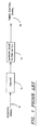
- a conventional timing recovery system on the receiver's end for use in connection with data communication is shown in Figure 1 .
- the received signal 10 is first applied to a nonlinearity operator, such as the squarer 12.
- the output from the square 12 is then filtered by a narrow-band filter or a phase-locked loop 14 to retrieve the desired timing signal.
- the recovered timing signal can thus to be used to facilitate the sampler on the receiver's end to receive data.
- the conventional system generally fails to optimize the timing phase.
- FIG. 2 illustrates another conventional timing recovery system, commonly referred to as the "Early-Late" system, for optimizing the timing phase and frequency for synchronizing data receivers.
- a received signal 21 from a sampler 20 has samples in different phases (represented by Phase A and Phase B).
- the signal in one phase is filtered by a half-symbol-rate band-pass filter 22 to produce an EARLY sample, while the signal in another phase is filtered by another half-symbol-rate band-pass filter 23 to produce a LATE sample.
- the filtered signals are then applied to a nonlinearity operator, such as the squarers 24, 25, to generate their respective symbol components.
- a difference between the squared outputs is generated by an adder 26 as an error signal.
- the error signal can then be applied to a timing phase-locked loop 27 to recover a timing signal 28 for the sampler 20 to synchronize the received signal.
- the error signal should be zero.
- the phase-locked loop 27 will settle to one unique phase, which is thus the optimal timing sampling phase for a T-spaced equalizer.
- This technique is commonly called the "band-edge component maximization" technique in that it uses the band-edge energy in the received signal to track timing.
- the general goal is to keep the two samples, EARLY and LATE, roughly equal to derive their optimal sampling time, which is generally half-way between the two samples.
- the present invention reduces the problems in connection with the conventional timing recovery by varying the gain of the band-edge filtering in inverse proportion to the available band-edge energy in the received signal.
- the nonlinearized outputs from the "early-late" filter are first added together and then a reference value is subtracted. A small fraction of the result is subtracted from the filter gains of the two half-symbol-rate filters. As such, if the band-edge energy is small, then the sum of the nonlinearized outputs is small and only a very small amount is subtracted from the timing filter gain values. If the band-edge energy is large, then the filter gains will be reduced.
- the present invention overcomes at least one of the problems of the conventional technique by changing the gain of the timing PLL which is effectively an adaptive filter.
- a timing error signal is generated whose gain is independent of the channel, resulting in a constant tracking range.
- FIG. 3 a system block diagram of the present invention is shown.
- the sampler output 42 at 2-times the symbol rate is alternately applied to BPF's 30 and 32, which receive their respective inputs at the symbol rate.
- BPF band-pass filters
- a BPF gain unit is implemented to adjust the gain of the received samples in response to the signal level at the adder 36.
- the timing PLL 39 acting effectively as a filter, functions dynamically the same for different channels.
- the outputs from the squarers 34, 35 are added by an adder 36 to generate a sum S i and a reference level, T ref , subtracted to produce a signal equal to (S i -T ref ), which indicates whether the timing recovery gain needs to be increased or decreased.
- the (S i - T ref ) signal is then multiplied by a multiplication factor K, a value much less than 1, and its negative accumulated by an accumulator 43 to generate a gain factor, G i , 41 for adjusting the BPF gain 31, 33.
- G i G i-1 - (S i - T ref ) K, where K is much less than 1.
- the gain factor 41, G i may be implemented anywhere between node A, A' and nodes B and B'.
- An example may be to apply the gain factor Gi to the input signals to the BPF's 30, 32 at nodes A and A'.
- the gain of the band-edge filtering can thus be varied in inverse proportion to the available band-edge energy in the received signal 42. As such, if the band-edge energy is small, then the sum of the squarer outputs at the adder 36 is small, which thereafter increases the BPF gains 31, 33 by a small amount. If the band,edge energy is large, i.e. less attenuation, then the filter gains 31, 33 will be reduced.
- FIG. 4 graphically illustrates a bandpass filter which can be implemented with the timing recovery system of the present invention.
- the gain factor G i which is normally a fixed multiplication factor for the bandpass filter, is multiplied to the received sampled signal 400.
- the gain-adjusted sampled signal is then subtracted by a scaled feedback, where ⁇ (the pole position in a z-transform plane) is between 0 and 1 (generally less than 0.1).
- ⁇ and G i can be complementarily designed by those skilled in the art in implementing their filters.
- FIG. 5 graphically illustrates a phase-locked loop to generate the timing phase signal from the timing error signal. Note that the gain factors 501, 502 can be complementarily designed by those skilled in the art in implementing their desired filters.
Landscapes
- Engineering & Computer Science (AREA)
- Computer Networks & Wireless Communication (AREA)
- Signal Processing (AREA)
- Synchronisation In Digital Transmission Systems (AREA)
Applications Claiming Priority (2)
| Application Number | Priority Date | Filing Date | Title |
|---|---|---|---|
| US283727 | 1994-08-01 | ||
| US08/283,727 US5454015A (en) | 1994-08-01 | 1994-08-01 | Adaptive timing recovery with gain adjustment |
Publications (2)
| Publication Number | Publication Date |
|---|---|
| EP0696115A2 true EP0696115A2 (de) | 1996-02-07 |
| EP0696115A3 EP0696115A3 (de) | 1996-12-18 |
Family
ID=23087298
Family Applications (1)
| Application Number | Title | Priority Date | Filing Date |
|---|---|---|---|
| EP95111441A Withdrawn EP0696115A3 (de) | 1994-08-01 | 1995-07-20 | Adaptive Taktrückgewinnung mit Verstärkungsregelung |
Country Status (3)
| Country | Link |
|---|---|
| US (1) | US5454015A (de) |
| EP (1) | EP0696115A3 (de) |
| JP (1) | JPH0865291A (de) |
Families Citing this family (16)
| Publication number | Priority date | Publication date | Assignee | Title |
|---|---|---|---|---|
| US7423983B1 (en) * | 1999-09-20 | 2008-09-09 | Broadcom Corporation | Voice and data exchange over a packet based network |
| US6882711B1 (en) | 1999-09-20 | 2005-04-19 | Broadcom Corporation | Packet based network exchange with rate synchronization |
| US6765931B1 (en) * | 1999-04-13 | 2004-07-20 | Broadcom Corporation | Gateway with voice |
| US6549587B1 (en) | 1999-09-20 | 2003-04-15 | Broadcom Corporation | Voice and data exchange over a packet based network with timing recovery |
| US6757367B1 (en) * | 1999-09-20 | 2004-06-29 | Broadcom Corporation | Packet based network exchange with rate synchronization |
| US7924752B2 (en) | 1999-09-20 | 2011-04-12 | Broadcom Corporation | Voice and data exchange over a packet based network with AGC |
| US7161931B1 (en) * | 1999-09-20 | 2007-01-09 | Broadcom Corporation | Voice and data exchange over a packet based network |
| US7920697B2 (en) * | 1999-12-09 | 2011-04-05 | Broadcom Corp. | Interaction between echo canceller and packet voice processing |
| WO2001043334A2 (en) * | 1999-12-13 | 2001-06-14 | Broadcom Corporation | Voice gateway with downstream voice synchronization |
| US8233575B2 (en) * | 2001-10-25 | 2012-07-31 | Zenith Electronics Llc | Open loop cyclostationarity based timing recovery for accelerated timing acquisition in frequency selective channels |
| US6573761B1 (en) * | 2002-04-08 | 2003-06-03 | Agilent Technologies, Inc. | Timebase for sampling an applied signal having a synchronous trigger |
| US6650101B2 (en) * | 2002-04-08 | 2003-11-18 | Agilent Technologies, Inc. | Timebase for sampling an input signal having a synchronous trigger |
| US8542778B2 (en) * | 2005-10-26 | 2013-09-24 | Zenith Electronics Llc | Closed loop power normalized timing recovery for 8 VSB modulated signals |
| US8189724B1 (en) | 2005-10-26 | 2012-05-29 | Zenith Electronics Llc | Closed loop power normalized timing recovery for 8 VSB modulated signals |
| US8036332B2 (en) | 2007-03-30 | 2011-10-11 | 4472314 Canada Inc. | Communication signal symbol timing error detection and recovery |
| RU2539612C2 (ru) * | 2013-04-23 | 2015-01-20 | Закрытое акционерное общество "АВИА-ПРОЕКТ" | Конструкция силового каркаса ветролета |
Family Cites Families (4)
| Publication number | Priority date | Publication date | Assignee | Title |
|---|---|---|---|---|
| US4805191A (en) * | 1987-11-25 | 1989-02-14 | Motorola, Inc. | Modem with improved timing recovery using equalized data |
| US4910467A (en) * | 1988-11-02 | 1990-03-20 | Motorola, Inc. | Method and apparatus for decoding a quadrature modulated signal |
| FR2649845B1 (fr) * | 1989-07-12 | 1994-05-13 | Alcatel Transmission Faisceaux H | Dispositif de reception pour faisceau hertzien numerique |
| JP2721454B2 (ja) * | 1992-01-27 | 1998-03-04 | 富士通株式会社 | タイミング抽出方法 |
-
1994
- 1994-08-01 US US08/283,727 patent/US5454015A/en not_active Expired - Lifetime
-
1995
- 1995-07-20 EP EP95111441A patent/EP0696115A3/de not_active Withdrawn
- 1995-07-31 JP JP19443495A patent/JPH0865291A/ja not_active Ceased
Non-Patent Citations (1)
| Title |
|---|
| None |
Also Published As
| Publication number | Publication date |
|---|---|
| JPH0865291A (ja) | 1996-03-08 |
| EP0696115A3 (de) | 1996-12-18 |
| US5454015A (en) | 1995-09-26 |
Similar Documents
| Publication | Publication Date | Title |
|---|---|---|
| US5454015A (en) | Adaptive timing recovery with gain adjustment | |
| US4669092A (en) | Arrangement for receiving digital data comprising an arrangement for adaptive timing recovery | |
| EP0526573B1 (de) | Taktrückgewinnungsschaltung ohne anhebung des jitters | |
| EP1552641B1 (de) | Optimales interpolatorverfahren und vorrichtung zur digitalen timing-einstellung | |
| JPH03236652A (ja) | 適応位相検出同期方法 | |
| JPH0774793A (ja) | データ受信方法とその装置 | |
| WO2007038777A2 (en) | Carrier phase independent symbol timing recovery methods for vsb receivers | |
| JPH11136597A (ja) | シンボルタイミング回復装置及び方法 | |
| EP0461931B1 (de) | Adaptiver Entzerrer, der zur wirksamen Beseitigung eines nachbleibenden Schwunds in einem entzerrten Signal geeignet ist | |
| KR100866867B1 (ko) | 타이밍 복원 장치 | |
| JP2785858B2 (ja) | 高速制御適応フィルタを用いた受信方式 | |
| CN112118200A (zh) | 跟踪方法及系统 | |
| CN114465691A (zh) | 一种低复杂度的恒包络相位调制信号采样偏差估计和补偿方法及系统 | |
| US7106818B2 (en) | Method and apparatus for timing recovery based on dispersion characterization and components therefor | |
| JP2967684B2 (ja) | サンプリング位相制御回路 | |
| JPH10210019A (ja) | クロック再生装置およびクロック再生方法 | |
| US20040047410A1 (en) | Method and apparatus for compensating for phase error of digital signal | |
| JP2570126B2 (ja) | 復調装置 | |
| US20060176980A1 (en) | Symbol timing recovery apparatus usable with VSB receiver and method thereof | |
| KR100937404B1 (ko) | 타이밍 복원 장치 | |
| JP2838962B2 (ja) | 搬送波再生方式 | |
| KR100330236B1 (ko) | 무선통신시스템에서 수신단의 타이밍 복구회로 | |
| JP2592390B2 (ja) | 適応自動等化方式 | |
| JPH03263907A (ja) | Agc回路及びfsk復調装置 | |
| KR100209647B1 (ko) | 디지탈 데이타의 타이밍 복원시스템 |
Legal Events
| Date | Code | Title | Description |
|---|---|---|---|
| PUAI | Public reference made under article 153(3) epc to a published international application that has entered the european phase |
Free format text: ORIGINAL CODE: 0009012 |
|
| AK | Designated contracting states |
Kind code of ref document: A2 Designated state(s): DE FR GB |
|
| PUAL | Search report despatched |
Free format text: ORIGINAL CODE: 0009013 |
|
| AK | Designated contracting states |
Kind code of ref document: A3 Designated state(s): DE FR GB |
|
| 17P | Request for examination filed |
Effective date: 19970616 |
|
| RAP1 | Party data changed (applicant data changed or rights of an application transferred) |
Owner name: CONEXANT SYSTEMS, INC. |
|
| 17Q | First examination report despatched |
Effective date: 20010531 |
|
| GRAP | Despatch of communication of intention to grant a patent |
Free format text: ORIGINAL CODE: EPIDOSNIGR1 |
|
| STAA | Information on the status of an ep patent application or granted ep patent |
Free format text: STATUS: THE APPLICATION IS DEEMED TO BE WITHDRAWN |
|
| 18D | Application deemed to be withdrawn |
Effective date: 20040210 |