EP0695254B1 - Welle mit veränderlicher länge - Google Patents
Welle mit veränderlicher länge Download PDFInfo
- Publication number
- EP0695254B1 EP0695254B1 EP94915441A EP94915441A EP0695254B1 EP 0695254 B1 EP0695254 B1 EP 0695254B1 EP 94915441 A EP94915441 A EP 94915441A EP 94915441 A EP94915441 A EP 94915441A EP 0695254 B1 EP0695254 B1 EP 0695254B1
- Authority
- EP
- European Patent Office
- Prior art keywords
- shaft member
- wedge
- wedges
- inner shaft
- coupling
- Prior art date
- Legal status (The legal status is an assumption and is not a legal conclusion. Google has not performed a legal analysis and makes no representation as to the accuracy of the status listed.)
- Expired - Lifetime
Links
- 230000008878 coupling Effects 0.000 claims abstract description 33
- 238000010168 coupling process Methods 0.000 claims abstract description 33
- 238000005859 coupling reaction Methods 0.000 claims abstract description 33
- 230000000712 assembly Effects 0.000 claims description 3
- 238000000429 assembly Methods 0.000 claims description 3
- 239000007787 solid Substances 0.000 claims 3
- 230000005540 biological transmission Effects 0.000 claims 1
- 230000000717 retained effect Effects 0.000 abstract 1
- 230000000694 effects Effects 0.000 description 4
- 238000009434 installation Methods 0.000 description 2
- 241000219109 Citrullus Species 0.000 description 1
- 235000012828 Citrullus lanatus var citroides Nutrition 0.000 description 1
- 230000003197 catalytic effect Effects 0.000 description 1
- 230000006835 compression Effects 0.000 description 1
- 238000007906 compression Methods 0.000 description 1
- 238000004519 manufacturing process Methods 0.000 description 1
Images


Classifications
-
- B—PERFORMING OPERATIONS; TRANSPORTING
- B62—LAND VEHICLES FOR TRAVELLING OTHERWISE THAN ON RAILS
- B62D—MOTOR VEHICLES; TRAILERS
- B62D1/00—Steering controls, i.e. means for initiating a change of direction of the vehicle
- B62D1/02—Steering controls, i.e. means for initiating a change of direction of the vehicle vehicle-mounted
- B62D1/16—Steering columns
- B62D1/18—Steering columns yieldable or adjustable, e.g. tiltable
- B62D1/185—Steering columns yieldable or adjustable, e.g. tiltable adjustable by axial displacement, e.g. telescopically
-
- F—MECHANICAL ENGINEERING; LIGHTING; HEATING; WEAPONS; BLASTING
- F16—ENGINEERING ELEMENTS AND UNITS; GENERAL MEASURES FOR PRODUCING AND MAINTAINING EFFECTIVE FUNCTIONING OF MACHINES OR INSTALLATIONS; THERMAL INSULATION IN GENERAL
- F16C—SHAFTS; FLEXIBLE SHAFTS; ELEMENTS OR CRANKSHAFT MECHANISMS; ROTARY BODIES OTHER THAN GEARING ELEMENTS; BEARINGS
- F16C3/00—Shafts; Axles; Cranks; Eccentrics
- F16C3/02—Shafts; Axles
- F16C3/03—Shafts; Axles telescopic
-
- F—MECHANICAL ENGINEERING; LIGHTING; HEATING; WEAPONS; BLASTING
- F16—ENGINEERING ELEMENTS AND UNITS; GENERAL MEASURES FOR PRODUCING AND MAINTAINING EFFECTIVE FUNCTIONING OF MACHINES OR INSTALLATIONS; THERMAL INSULATION IN GENERAL
- F16D—COUPLINGS FOR TRANSMITTING ROTATION; CLUTCHES; BRAKES
- F16D3/00—Yielding couplings, i.e. with means permitting movement between the connected parts during the drive
- F16D3/02—Yielding couplings, i.e. with means permitting movement between the connected parts during the drive adapted to specific functions
- F16D3/06—Yielding couplings, i.e. with means permitting movement between the connected parts during the drive adapted to specific functions specially adapted to allow axial displacement
-
- F—MECHANICAL ENGINEERING; LIGHTING; HEATING; WEAPONS; BLASTING
- F16—ENGINEERING ELEMENTS AND UNITS; GENERAL MEASURES FOR PRODUCING AND MAINTAINING EFFECTIVE FUNCTIONING OF MACHINES OR INSTALLATIONS; THERMAL INSULATION IN GENERAL
- F16C—SHAFTS; FLEXIBLE SHAFTS; ELEMENTS OR CRANKSHAFT MECHANISMS; ROTARY BODIES OTHER THAN GEARING ELEMENTS; BEARINGS
- F16C2326/00—Articles relating to transporting
- F16C2326/20—Land vehicles
- F16C2326/24—Steering systems, e.g. steering rods or columns
-
- Y—GENERAL TAGGING OF NEW TECHNOLOGICAL DEVELOPMENTS; GENERAL TAGGING OF CROSS-SECTIONAL TECHNOLOGIES SPANNING OVER SEVERAL SECTIONS OF THE IPC; TECHNICAL SUBJECTS COVERED BY FORMER USPC CROSS-REFERENCE ART COLLECTIONS [XRACs] AND DIGESTS
- Y10—TECHNICAL SUBJECTS COVERED BY FORMER USPC
- Y10T—TECHNICAL SUBJECTS COVERED BY FORMER US CLASSIFICATION
- Y10T403/00—Joints and connections
- Y10T403/70—Interfitted members
- Y10T403/7047—Radially interposed shim or bushing
- Y10T403/7061—Resilient
-
- Y—GENERAL TAGGING OF NEW TECHNOLOGICAL DEVELOPMENTS; GENERAL TAGGING OF CROSS-SECTIONAL TECHNOLOGIES SPANNING OVER SEVERAL SECTIONS OF THE IPC; TECHNICAL SUBJECTS COVERED BY FORMER USPC CROSS-REFERENCE ART COLLECTIONS [XRACs] AND DIGESTS
- Y10—TECHNICAL SUBJECTS COVERED BY FORMER USPC
- Y10T—TECHNICAL SUBJECTS COVERED BY FORMER US CLASSIFICATION
- Y10T74/00—Machine element or mechanism
- Y10T74/21—Elements
- Y10T74/2142—Pitmans and connecting rods
Definitions
- This invention relates generally to shaft assemblies which are variable in length and more particularly to a shaft assembly which is adaptable for use as the steering shaft in steering devices of motor vehicles.
- the shaft assembly which is attached to the steering column at one end and the steering gear at the other end, must be extended axially in order to be installed to its nominal working position.
- the shaft assembly is often surrounded by other engine compartment components such as the exhaust manifold, catalytic convertor, or brake booster and during assembly is often hidden and hard to reach. Therefore, a low force to slide is essential for ease of installation.
- An additional requirement for the shaft assembly is the ability to accommodate any body/chassis flex due to road conditions.
- EP-A-0 446 428 discloses a steering shaft coupling of the type defined in the preamble of claim 1.
- This known steering shaft coupling comprises an assembly with two wedges located between coaxial outer and inner shafts and biassing means pulling the wedges away from one another.
- a steering shaft coupling of the type having an outer tubular shaft member, a coaxial inner shaft member slidably inserted within the outer tubular shaft member and defining a clearance space therebetween, and torque being transmitted between the inner shaft member and the outer shaft member through a wedge assembly, characterised by a plurality of enlarged spaces between said outer shaft member and said inner shaft member connected by said clearance space; there being a plurality of wedge assemblies between the inner shaft member and the outer shaft member, each said wedge assembly comprising first and second wedges, each wedge being located in an enlarged space; there being a biasing means connecting said first and second wedges and pulling said second wedge into said clearance space and generally towards said first wedge; and a locking means is provided for retaining one of said wedges in a fixed position between the inner shaft member and the outer tubular shaft member.
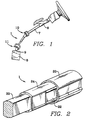
- FIG. 1 shows a steering shaft coupling 1 applied to the steering system of an automobile.
- the steering shaft coupling 1 is interposed between a steering main shaft 7 extending from a steering column 6 and a steering gear shaft 9 attached to a steering gear case 8.
- the steering shaft coupling 1 is connected to the steering main shaft 7 and the steering gear shaft 9 by a pair of universal joints 10, 11.
- FIG. 2 shows a perspective view of the coupling 1. Portions of the coupling 1 have been removed to show the details of the coupling 1.
- the coupling 1 is comprised of three main components, an outer tubular shaft member 20, an inner shaft member 24 and a plurality of wedge members 22 located between the outer shaft member 20 and the inner shaft member 24.
- a lower shaft 30 is connected to the inner shaft member 24.
- the outer shaft member 20 may be axially extended such that universal joint 11 is attached directly to the outer shaft member 20.
- An upper shaft member (not shown) may be used to connect the outer shaft member 20 to the universal joint 10.
- the lower shaft 30 is preferably slidable within the inner shaft member 24.
- Each wedge member 22 consists of a pair of wedges 40 connected by a wedge spring 42.
- the wedges 40 have an approximate triangular shape.
- the sides of the wedges 40 which contact the outer tubular shaft member 20 and the inner shaft member 24 are not parallel.
- the portions of the outer tubular shaft member 20 and the inner shaft member 24 which contact the wedges 40 are also not parallel and define a space, this space having an approximate triangular shape.
- the characteristics which allow this coupling 1 to work are wedge angle, wedge spring load and coefficient of friction between the wedges 40 and the shaft members 20, 24.
- Proper selection of the wedge shape (i.e. angle) and the coefficient or friction between the wedge 40 and the outer tubular shaft member 20 and the inner shaft member 24 results in a "locking wedge,” a wedge which tends to lock in place between the two shaft members 20, 24.
- the wedges 40 With a locking wedge, the wedges 40 will tend to stay fixed in between the two shafts 20, 24 as torque increases, rather than be squeezed out, like a watermelon seed.
- the means for biasing 42 urges into the clearance space 28 between shaft members 20, 24. The locking effect keeps the wedge from being squeezed out as torque increases.
- FIG. 4 illustrates the determination of the proper wedge angle.
- the desired locking effect is achieved when the force (q t ) tending to eject the wedge 40 from between the two shaft members 20, 24 is zero or less than zero or less than zero.
- the spring force, q s is a tension force caused by the connecting wedge spring 42.
- the spring force may also be a compression force pushing the wedges 40 into the space between the shaft members 20, 24.
- the outer tubular shaft member 20, and the inner shaft member 24 each have shape similar to a double - V.
- Four wedges 40 are connected in pairs by a wedge spring or biasing member 42.
- An alternate embodiment of coupling 1 showing a different shape for shaft members 20a, 24a and wedge members 22a is shown in FIG. 5.
- the preferred embodiment of coupling 1 is designed to use locking wedges to transmit torque through two of the wedges 40, these wedges being diagonal opposite one another, while the other two diagonal opposite wedges 40 are pulled into any clearance in the coupling 1 by the wedge spring 42 therefore compensating for any manufacturing tolerances and any wear on the wedge surfaces.
- the proper selection of the wedge angle and the spring force, q s can result in a coupling 1 which has no rotational clearance. This occurs because the unloaded wedges 40 are pulled into any clearance in the coupling 1 by the wedge spring 42 such that when the direction of the rotational torque changes, the now loaded wedges (previously unloaded) are already tight in the coupling 1.
Landscapes
- Engineering & Computer Science (AREA)
- General Engineering & Computer Science (AREA)
- Mechanical Engineering (AREA)
- Chemical & Material Sciences (AREA)
- Combustion & Propulsion (AREA)
- Transportation (AREA)
- Ocean & Marine Engineering (AREA)
- Steering Controls (AREA)
- Shafts, Cranks, Connecting Bars, And Related Bearings (AREA)
- Valve Device For Special Equipments (AREA)
Claims (4)
- Kupplung für eine Lenksäule der Art, die ein äußeres rohrförmiges Säulenglied (20) und ein koaxiales inneres Säulenglied (24) hat, das gleitfähig innerhalb des äußeren rohrförmigen Säulenglieds (20) eingesetzt ist und einen Freiraum dazwischen definiert, wobei Drehmoment zwischen dem inneren Säulenglied (24) und dem äußeren Säulenglied (20) über eine Keilanordnung (22) übertragen wird, gekennzeichnet durch eine Vielzahl von vergrößerten Räumen (23) zwischen dem äußeren Säulenglied (20) und dem inneren Säulenglied (24), die durch den Freiraum (28) verbunden sind, mit einer Vielzahl von Keilanordnungen (22) zwischen dem inneren Säulenglied (24) und dem äußeren Säulenglied (20), wobei jede Keilanordnung (22) erste und zweite Keile (40) aufweist, wobei jeder Keil (40) in einem vergrößerten Raum angeordnet ist, mit einer Vorspanneinrichtung (42), die die ersten und zweiten Keile (40) verbindet und den zweiten Keil (40) in den Freiraum (28) und allgemein auf den ersten Keil (40) zu zieht, wobei ein Verriegelungsmittel zum Halten eines der Keile (40) in einer festen Stellung zwischen dem inneren Säulenglied (24) und dem äußeren rohrförmigen Säulenglied (20) vorgesehen ist.
- Kupplung für eine Lenksäule nach Anspruch 1, bei der das innere Säulenglied (24), rohrförmig ist und ein koaxiales massives Säulenglied (30) gleitfähig innerhalb des rohrförmigen inneren Säulenglieds (24) eingesetz: ist, wobei die Gestalten des inneren rohrförmigen Säulenglieds (24) und des massiven Säulenglieds (30) die Übertragung von Drehmoment zwischen dem massiven Säulenglied (30) und dem inneren Säulenglied (24) gestatten.
- Kupplung für eine Lenksäule nach Anspruch 1 oder 2, bei der ein Winkel zwischen einer zentralen Achse A eines der Keile (40) und dem äußeren rohrförmigen Säulenglied (20) als Winkel σ definiert ist und der Winkel zwischen der zentralen Achse A dieses Keils (40) und dem inneren Säulenglied (24) einen Winkel α definiert, wobei zwischen dem Keil (40) und dem inneren Säulenglied (24) und dem äußeren Säulenglied (20) ein Reibungskoeffizient µ vorhanden ist, wobei das Verriegelungsmittel zum Halten des Keils (40) definiert ist als

- Kupplung für eine Lenksäule nach Anspruch 1, 2 oder 3, bei der die Kupplung zum Aufrechterhalten des Erfordernisses einer geringen axialen Kraft für ein relatives Gleiten zwischen den Säulengliedern konstruiert ist.
Applications Claiming Priority (3)
| Application Number | Priority Date | Filing Date | Title |
|---|---|---|---|
| US08/056,271 US5477750A (en) | 1993-05-03 | 1993-05-03 | Variable length shaft assembly |
| PCT/US1994/004791 WO1994025325A1 (en) | 1993-05-03 | 1994-04-29 | Variable length shaft assembly |
| US56271 | 1998-04-07 |
Publications (2)
| Publication Number | Publication Date |
|---|---|
| EP0695254A1 EP0695254A1 (de) | 1996-02-07 |
| EP0695254B1 true EP0695254B1 (de) | 1996-11-20 |
Family
ID=22003316
Family Applications (1)
| Application Number | Title | Priority Date | Filing Date |
|---|---|---|---|
| EP94915441A Expired - Lifetime EP0695254B1 (de) | 1993-05-03 | 1994-04-29 | Welle mit veränderlicher länge |
Country Status (9)
| Country | Link |
|---|---|
| US (1) | US5477750A (de) |
| EP (1) | EP0695254B1 (de) |
| JP (1) | JPH09501366A (de) |
| CN (1) | CN1122588A (de) |
| AU (1) | AU6670094A (de) |
| BR (1) | BR9406389A (de) |
| CA (1) | CA2161105A1 (de) |
| DE (1) | DE69400957D1 (de) |
| WO (1) | WO1994025325A1 (de) |
Families Citing this family (25)
| Publication number | Priority date | Publication date | Assignee | Title |
|---|---|---|---|---|
| DE19504036C1 (de) * | 1995-02-08 | 1996-06-27 | Lemfoerder Metallwaren Ag | Sicherheitslenkwelle |
| DE19518130C2 (de) * | 1995-05-17 | 1997-05-15 | Lemfoerder Metallwaren Ag | Sicherheitslenksäule eines Kraftfahrzeuges |
| US5560650A (en) * | 1995-07-24 | 1996-10-01 | General Motors Corporation | Intermediate steering shaft |
| DE19750005C1 (de) * | 1997-11-12 | 1999-04-22 | Supervis Ets | Längenveränderbare Lenkspindel für Lenkvorrichtungen bei Kraftfahrzeugen |
| US6099037A (en) * | 1998-10-30 | 2000-08-08 | The Torrington Company | Collapsible shaft having tunable collapse load for motor vehicle |
| BR9903852A (pt) * | 1999-09-10 | 2001-04-24 | Dana Albarus S A Ind E Com | Aperfeiçoamento em coluna intermediária de direção |
| US6368225B1 (en) * | 1999-12-30 | 2002-04-09 | Spicer Driveshaft, Inc. | Axially collapsible driveshaft assembly and method of manufacturing same |
| US6371519B1 (en) | 2000-10-23 | 2002-04-16 | Daimlerchrysler Corporation | Steering shaft support mechanism |
| FR2828856B1 (fr) * | 2001-08-22 | 2003-12-05 | Sai Automotive Allibert Ind | Dispositif destine a masquer les jeux entre une planche de bord et un element d'habillage lie a une colonne de direction reglable |
| US7179173B2 (en) | 2002-03-25 | 2007-02-20 | Nbgs International Inc. | Control system for water amusement devices |
| AU2003211225A1 (en) * | 2002-04-17 | 2003-10-27 | Nsk Ltd. | Method of assembling steering columns |
| GB0328695D0 (en) * | 2003-12-11 | 2004-01-14 | Trw Lucas Varity Electric | A steering column assembly |
| ES2238009B2 (es) * | 2004-01-28 | 2007-07-16 | Melchor Daumal Castellon | Eje intermedio de baja carga de deslizamiento de la columna de direccion de vehiculos automoviles. |
| US20070051036A1 (en) * | 2005-04-20 | 2007-03-08 | Henry Jeffery W | Tree with elevated structure |
| US20060243089A1 (en) * | 2005-04-28 | 2006-11-02 | Cymbal William D | Telescoping steering shaft |
| JP4610465B2 (ja) * | 2005-07-29 | 2011-01-12 | 富士機工株式会社 | ステアリングシャフト |
| GB2429761A (en) * | 2005-09-03 | 2007-03-07 | Nsk Steering Sys Europ Ltd | Temperature accommodating vehicl steering column bush |
| US7574940B2 (en) * | 2005-11-23 | 2009-08-18 | Delphi Technologies, Inc. | Steering column assembly including anti-rotation device |
| JP5119707B2 (ja) * | 2006-06-29 | 2013-01-16 | 日本精工株式会社 | 伸縮軸 |
| US9643266B1 (en) | 2006-10-27 | 2017-05-09 | Battenfeld Technologies, Inc. | Extendable folding saw |
| DE102010037312B3 (de) * | 2010-09-03 | 2012-01-12 | Thyssenkrupp Presta Ag | Lenksäule für ein Kraftfahrzeug |
| US10022793B2 (en) * | 2011-05-12 | 2018-07-17 | Santoku Corporation | Alloy flake production apparatus and production method for raw material alloy flakes for rare earth magnet using the apparatus |
| CN103270906B (zh) * | 2013-05-23 | 2015-01-21 | 江苏圣宏农业科技有限公司 | 一种伸缩育苗穴盘 |
| US9080596B2 (en) * | 2013-06-25 | 2015-07-14 | Deere & Company | Double ended extendable driveshaft for auto header hookup |
| DE102024116299A1 (de) * | 2024-06-11 | 2025-12-11 | Schaeffler Technologies AG & Co. KG | Verstelleinheit einer Lenksäule |
Family Cites Families (8)
| Publication number | Priority date | Publication date | Assignee | Title |
|---|---|---|---|---|
| US3318170A (en) * | 1965-08-05 | 1967-05-09 | Bendix Corp | No-lash axially movable steering column |
| US3444753A (en) * | 1967-12-14 | 1969-05-20 | Bendix Corp | No-lash axially movable steering column |
| US3665777A (en) * | 1969-12-15 | 1972-05-30 | Ford Motor Co | Energy absorbing steering column |
| JPS5929147Y2 (ja) * | 1979-02-24 | 1984-08-22 | トヨタ自動車株式会社 | 弾性軸継手 |
| US4622022A (en) * | 1983-06-20 | 1986-11-11 | Neapco, Inc. | Telescoping tubes for torque transmission |
| DE4008481A1 (de) * | 1990-03-16 | 1991-09-19 | Reiche & Co | Als teleskoprohr ausgebildete, vorzugsweise durch handkraft hoehenverstellbare kraftfahrzeuglenksaeule |
| US5115691A (en) * | 1991-09-03 | 1992-05-26 | General Motors Corporation | Collapsible shaft assembly |
| US5235734A (en) * | 1991-11-04 | 1993-08-17 | Itt Corporation | Collapsible steering shaft apparatus and method of making same |
-
1993
- 1993-05-03 US US08/056,271 patent/US5477750A/en not_active Expired - Lifetime
-
1994
- 1994-04-29 CA CA002161105A patent/CA2161105A1/en not_active Abandoned
- 1994-04-29 DE DE69400957T patent/DE69400957D1/de not_active Expired - Lifetime
- 1994-04-29 AU AU66700/94A patent/AU6670094A/en not_active Abandoned
- 1994-04-29 CN CN94191989A patent/CN1122588A/zh active Pending
- 1994-04-29 BR BR9406389A patent/BR9406389A/pt not_active Application Discontinuation
- 1994-04-29 WO PCT/US1994/004791 patent/WO1994025325A1/en not_active Ceased
- 1994-04-29 JP JP6524595A patent/JPH09501366A/ja active Pending
- 1994-04-29 EP EP94915441A patent/EP0695254B1/de not_active Expired - Lifetime
Also Published As
| Publication number | Publication date |
|---|---|
| EP0695254A1 (de) | 1996-02-07 |
| BR9406389A (pt) | 1996-01-16 |
| DE69400957D1 (de) | 1997-01-02 |
| WO1994025325A1 (en) | 1994-11-10 |
| US5477750A (en) | 1995-12-26 |
| CN1122588A (zh) | 1996-05-15 |
| AU6670094A (en) | 1994-11-21 |
| JPH09501366A (ja) | 1997-02-10 |
| CA2161105A1 (en) | 1994-11-10 |
Similar Documents
| Publication | Publication Date | Title |
|---|---|---|
| US5477750A (en) | Variable length shaft assembly | |
| US5507203A (en) | Variable length shaft assembly | |
| US5628578A (en) | Alternate pinch bolt yoke construction | |
| US5577859A (en) | Arrangement for connecting a rotatable shaft having an end portion with channel toothing formed thereon and a structural component | |
| US8434582B2 (en) | All wheel drive system | |
| GB2293339A (en) | Method of manufacturing a shock absorbing type steering shaft | |
| US4563912A (en) | Telescoping polygonal steering column | |
| US6530599B1 (en) | Shock absorbing type steering shaft | |
| US7288029B1 (en) | Propshaft with crash-worthiness | |
| EP0848678B1 (de) | Schnappverbindungssystem | |
| US6368225B1 (en) | Axially collapsible driveshaft assembly and method of manufacturing same | |
| US4909774A (en) | Device for adjustment of universal joint shafts | |
| EP0683084A2 (de) | Energieabsorbierende Zwischenwelle | |
| US6068296A (en) | Shock absorbing type steering column assembly | |
| WO2007036343A1 (de) | Gelenkwelle und rollverschiebeeinheit hierfür | |
| US7044860B2 (en) | Slip joint for vehicle driveshaft assembly | |
| US5201545A (en) | Steering shaft for motor vehicles | |
| EP0203845B1 (de) | Lösbare Verbindungsvorrichtung, insbesondere für Kraftfahrzeuglenksäule | |
| JPH11303846A (ja) | プロペラシャフト | |
| EP1674749A1 (de) | Verfahren zum Herstellen eines Gleitgelenks von Keilwelletyp | |
| US8162764B2 (en) | Constant velocity universal joint | |
| GB2172376A (en) | Propeller shaft joints | |
| JPH0714102Y2 (ja) | ステアリングシャフトの結合構造 | |
| JP4846216B2 (ja) | 動力伝達構造 | |
| CN119018228A (zh) | 用于配合转向系统部件的有齿连接件 |
Legal Events
| Date | Code | Title | Description |
|---|---|---|---|
| PUAI | Public reference made under article 153(3) epc to a published international application that has entered the european phase |
Free format text: ORIGINAL CODE: 0009012 |
|
| 17P | Request for examination filed |
Effective date: 19951124 |
|
| AK | Designated contracting states |
Kind code of ref document: A1 Designated state(s): CH DE ES FR GB IT LI PT SE |
|
| GRAG | Despatch of communication of intention to grant |
Free format text: ORIGINAL CODE: EPIDOS AGRA |
|
| 17Q | First examination report despatched |
Effective date: 19960221 |
|
| GRAH | Despatch of communication of intention to grant a patent |
Free format text: ORIGINAL CODE: EPIDOS IGRA |
|
| GRAH | Despatch of communication of intention to grant a patent |
Free format text: ORIGINAL CODE: EPIDOS IGRA |
|
| GRAA | (expected) grant |
Free format text: ORIGINAL CODE: 0009210 |
|
| AK | Designated contracting states |
Kind code of ref document: B1 Designated state(s): CH DE ES FR GB IT LI PT SE |
|
| PG25 | Lapsed in a contracting state [announced via postgrant information from national office to epo] |
Ref country code: LI Effective date: 19961120 Ref country code: IT Free format text: LAPSE BECAUSE OF FAILURE TO SUBMIT A TRANSLATION OF THE DESCRIPTION OR TO PAY THE FEE WITHIN THE PRESCRIBED TIME-LIMIT;WARNING: LAPSES OF ITALIAN PATENTS WITH EFFECTIVE DATE BEFORE 2007 MAY HAVE OCCURRED AT ANY TIME BEFORE 2007. THE CORRECT EFFECTIVE DATE MAY BE DIFFERENT FROM THE ONE RECORDED. Effective date: 19961120 Ref country code: FR Effective date: 19961120 Ref country code: ES Free format text: THE PATENT HAS BEEN ANNULLED BY A DECISION OF A NATIONAL AUTHORITY Effective date: 19961120 Ref country code: CH Effective date: 19961120 |
|
| REF | Corresponds to: |
Ref document number: 69400957 Country of ref document: DE Date of ref document: 19970102 |
|
| PG25 | Lapsed in a contracting state [announced via postgrant information from national office to epo] |
Ref country code: SE Effective date: 19970220 Ref country code: PT Effective date: 19970220 |
|
| PG25 | Lapsed in a contracting state [announced via postgrant information from national office to epo] |
Ref country code: DE Effective date: 19970221 |
|
| EN | Fr: translation not filed | ||
| REG | Reference to a national code |
Ref country code: CH Ref legal event code: PL |
|
| PLBE | No opposition filed within time limit |
Free format text: ORIGINAL CODE: 0009261 |
|
| STAA | Information on the status of an ep patent application or granted ep patent |
Free format text: STATUS: NO OPPOSITION FILED WITHIN TIME LIMIT |
|
| 26N | No opposition filed | ||
| PG25 | Lapsed in a contracting state [announced via postgrant information from national office to epo] |
Ref country code: GB Free format text: LAPSE BECAUSE OF NON-PAYMENT OF DUE FEES Effective date: 19980429 |
|
| GBPC | Gb: european patent ceased through non-payment of renewal fee |
Effective date: 19980429 |