EP0694138B1 - Verfahren zur steuerung eines automatischen schaltgetriebes - Google Patents
Verfahren zur steuerung eines automatischen schaltgetriebes Download PDFInfo
- Publication number
- EP0694138B1 EP0694138B1 EP94914393A EP94914393A EP0694138B1 EP 0694138 B1 EP0694138 B1 EP 0694138B1 EP 94914393 A EP94914393 A EP 94914393A EP 94914393 A EP94914393 A EP 94914393A EP 0694138 B1 EP0694138 B1 EP 0694138B1
- Authority
- EP
- European Patent Office
- Prior art keywords
- driving
- parameter
- process according
- excess
- sum
- Prior art date
- Legal status (The legal status is an assumption and is not a legal conclusion. Google has not performed a legal analysis and makes no representation as to the accuracy of the status listed.)
- Expired - Lifetime
Links
- 238000000034 method Methods 0.000 title claims abstract description 18
- 230000000694 effects Effects 0.000 claims abstract description 18
- 230000001133 acceleration Effects 0.000 claims description 9
- 238000011156 evaluation Methods 0.000 claims description 9
- 230000009194 climbing Effects 0.000 claims description 5
- 238000005096 rolling process Methods 0.000 claims description 2
- 230000003247 decreasing effect Effects 0.000 claims 1
- 230000005540 biological transmission Effects 0.000 abstract description 11
- 238000010586 diagram Methods 0.000 description 4
- 230000006870 function Effects 0.000 description 4
- 239000000243 solution Substances 0.000 description 4
- 238000004364 calculation method Methods 0.000 description 2
- 238000012937 correction Methods 0.000 description 2
- 238000002347 injection Methods 0.000 description 2
- 239000007924 injection Substances 0.000 description 2
- 238000005259 measurement Methods 0.000 description 2
- 230000009849 deactivation Effects 0.000 description 1
- 230000007423 decrease Effects 0.000 description 1
- 238000013461 design Methods 0.000 description 1
- 239000000446 fuel Substances 0.000 description 1
- XDDAORKBJWWYJS-UHFFFAOYSA-N glyphosate Chemical compound OC(=O)CNCP(O)(O)=O XDDAORKBJWWYJS-UHFFFAOYSA-N 0.000 description 1
- 230000005484 gravity Effects 0.000 description 1
- 238000007620 mathematical function Methods 0.000 description 1
- 230000001960 triggered effect Effects 0.000 description 1
Images

Classifications
-
- F—MECHANICAL ENGINEERING; LIGHTING; HEATING; WEAPONS; BLASTING
- F16—ENGINEERING ELEMENTS AND UNITS; GENERAL MEASURES FOR PRODUCING AND MAINTAINING EFFECTIVE FUNCTIONING OF MACHINES OR INSTALLATIONS; THERMAL INSULATION IN GENERAL
- F16H—GEARING
- F16H61/00—Control functions within control units of change-speed- or reversing-gearings for conveying rotary motion ; Control of exclusively fluid gearing, friction gearing, gearings with endless flexible members or other particular types of gearing
- F16H61/02—Control functions within control units of change-speed- or reversing-gearings for conveying rotary motion ; Control of exclusively fluid gearing, friction gearing, gearings with endless flexible members or other particular types of gearing characterised by the signals used
- F16H61/0202—Control functions within control units of change-speed- or reversing-gearings for conveying rotary motion ; Control of exclusively fluid gearing, friction gearing, gearings with endless flexible members or other particular types of gearing characterised by the signals used the signals being electric
- F16H61/0204—Control functions within control units of change-speed- or reversing-gearings for conveying rotary motion ; Control of exclusively fluid gearing, friction gearing, gearings with endless flexible members or other particular types of gearing characterised by the signals used the signals being electric for gearshift control, e.g. control functions for performing shifting or generation of shift signal
- F16H61/0213—Control functions within control units of change-speed- or reversing-gearings for conveying rotary motion ; Control of exclusively fluid gearing, friction gearing, gearings with endless flexible members or other particular types of gearing characterised by the signals used the signals being electric for gearshift control, e.g. control functions for performing shifting or generation of shift signal characterised by the method for generating shift signals
-
- B—PERFORMING OPERATIONS; TRANSPORTING
- B60—VEHICLES IN GENERAL
- B60W—CONJOINT CONTROL OF VEHICLE SUB-UNITS OF DIFFERENT TYPE OR DIFFERENT FUNCTION; CONTROL SYSTEMS SPECIALLY ADAPTED FOR HYBRID VEHICLES; ROAD VEHICLE DRIVE CONTROL SYSTEMS FOR PURPOSES NOT RELATED TO THE CONTROL OF A PARTICULAR SUB-UNIT
- B60W30/00—Purposes of road vehicle drive control systems not related to the control of a particular sub-unit, e.g. of systems using conjoint control of vehicle sub-units
- B60W30/18—Propelling the vehicle
- B60W30/18009—Propelling the vehicle related to particular drive situations
- B60W30/18145—Cornering
-
- B—PERFORMING OPERATIONS; TRANSPORTING
- B60—VEHICLES IN GENERAL
- B60W—CONJOINT CONTROL OF VEHICLE SUB-UNITS OF DIFFERENT TYPE OR DIFFERENT FUNCTION; CONTROL SYSTEMS SPECIALLY ADAPTED FOR HYBRID VEHICLES; ROAD VEHICLE DRIVE CONTROL SYSTEMS FOR PURPOSES NOT RELATED TO THE CONTROL OF A PARTICULAR SUB-UNIT
- B60W50/00—Details of control systems for road vehicle drive control not related to the control of a particular sub-unit, e.g. process diagnostic or vehicle driver interfaces
- B60W2050/0001—Details of the control system
- B60W2050/0043—Signal treatments, identification of variables or parameters, parameter estimation or state estimation
- B60W2050/0052—Filtering, filters
-
- B—PERFORMING OPERATIONS; TRANSPORTING
- B60—VEHICLES IN GENERAL
- B60W—CONJOINT CONTROL OF VEHICLE SUB-UNITS OF DIFFERENT TYPE OR DIFFERENT FUNCTION; CONTROL SYSTEMS SPECIALLY ADAPTED FOR HYBRID VEHICLES; ROAD VEHICLE DRIVE CONTROL SYSTEMS FOR PURPOSES NOT RELATED TO THE CONTROL OF A PARTICULAR SUB-UNIT
- B60W2530/00—Input parameters relating to vehicle conditions or values, not covered by groups B60W2510/00 or B60W2520/00
-
- B—PERFORMING OPERATIONS; TRANSPORTING
- B60—VEHICLES IN GENERAL
- B60W—CONJOINT CONTROL OF VEHICLE SUB-UNITS OF DIFFERENT TYPE OR DIFFERENT FUNCTION; CONTROL SYSTEMS SPECIALLY ADAPTED FOR HYBRID VEHICLES; ROAD VEHICLE DRIVE CONTROL SYSTEMS FOR PURPOSES NOT RELATED TO THE CONTROL OF A PARTICULAR SUB-UNIT
- B60W2530/00—Input parameters relating to vehicle conditions or values, not covered by groups B60W2510/00 or B60W2520/00
- B60W2530/16—Driving resistance
-
- B—PERFORMING OPERATIONS; TRANSPORTING
- B60—VEHICLES IN GENERAL
- B60W—CONJOINT CONTROL OF VEHICLE SUB-UNITS OF DIFFERENT TYPE OR DIFFERENT FUNCTION; CONTROL SYSTEMS SPECIALLY ADAPTED FOR HYBRID VEHICLES; ROAD VEHICLE DRIVE CONTROL SYSTEMS FOR PURPOSES NOT RELATED TO THE CONTROL OF A PARTICULAR SUB-UNIT
- B60W2540/00—Input parameters relating to occupants
- B60W2540/10—Accelerator pedal position
-
- B—PERFORMING OPERATIONS; TRANSPORTING
- B60—VEHICLES IN GENERAL
- B60W—CONJOINT CONTROL OF VEHICLE SUB-UNITS OF DIFFERENT TYPE OR DIFFERENT FUNCTION; CONTROL SYSTEMS SPECIALLY ADAPTED FOR HYBRID VEHICLES; ROAD VEHICLE DRIVE CONTROL SYSTEMS FOR PURPOSES NOT RELATED TO THE CONTROL OF A PARTICULAR SUB-UNIT
- B60W2540/00—Input parameters relating to occupants
- B60W2540/18—Steering angle
-
- B—PERFORMING OPERATIONS; TRANSPORTING
- B60—VEHICLES IN GENERAL
- B60W—CONJOINT CONTROL OF VEHICLE SUB-UNITS OF DIFFERENT TYPE OR DIFFERENT FUNCTION; CONTROL SYSTEMS SPECIALLY ADAPTED FOR HYBRID VEHICLES; ROAD VEHICLE DRIVE CONTROL SYSTEMS FOR PURPOSES NOT RELATED TO THE CONTROL OF A PARTICULAR SUB-UNIT
- B60W2540/00—Input parameters relating to occupants
- B60W2540/30—Driving style
-
- B—PERFORMING OPERATIONS; TRANSPORTING
- B60—VEHICLES IN GENERAL
- B60W—CONJOINT CONTROL OF VEHICLE SUB-UNITS OF DIFFERENT TYPE OR DIFFERENT FUNCTION; CONTROL SYSTEMS SPECIALLY ADAPTED FOR HYBRID VEHICLES; ROAD VEHICLE DRIVE CONTROL SYSTEMS FOR PURPOSES NOT RELATED TO THE CONTROL OF A PARTICULAR SUB-UNIT
- B60W2552/00—Input parameters relating to infrastructure
- B60W2552/15—Road slope, i.e. the inclination of a road segment in the longitudinal direction
-
- B—PERFORMING OPERATIONS; TRANSPORTING
- B60—VEHICLES IN GENERAL
- B60W—CONJOINT CONTROL OF VEHICLE SUB-UNITS OF DIFFERENT TYPE OR DIFFERENT FUNCTION; CONTROL SYSTEMS SPECIALLY ADAPTED FOR HYBRID VEHICLES; ROAD VEHICLE DRIVE CONTROL SYSTEMS FOR PURPOSES NOT RELATED TO THE CONTROL OF A PARTICULAR SUB-UNIT
- B60W2552/00—Input parameters relating to infrastructure
- B60W2552/20—Road profile, i.e. the change in elevation or curvature of a plurality of continuous road segments
-
- B—PERFORMING OPERATIONS; TRANSPORTING
- B60—VEHICLES IN GENERAL
- B60W—CONJOINT CONTROL OF VEHICLE SUB-UNITS OF DIFFERENT TYPE OR DIFFERENT FUNCTION; CONTROL SYSTEMS SPECIALLY ADAPTED FOR HYBRID VEHICLES; ROAD VEHICLE DRIVE CONTROL SYSTEMS FOR PURPOSES NOT RELATED TO THE CONTROL OF A PARTICULAR SUB-UNIT
- B60W2552/00—Input parameters relating to infrastructure
- B60W2552/30—Road curve radius
-
- B—PERFORMING OPERATIONS; TRANSPORTING
- B60—VEHICLES IN GENERAL
- B60W—CONJOINT CONTROL OF VEHICLE SUB-UNITS OF DIFFERENT TYPE OR DIFFERENT FUNCTION; CONTROL SYSTEMS SPECIALLY ADAPTED FOR HYBRID VEHICLES; ROAD VEHICLE DRIVE CONTROL SYSTEMS FOR PURPOSES NOT RELATED TO THE CONTROL OF A PARTICULAR SUB-UNIT
- B60W2554/00—Input parameters relating to objects
-
- B—PERFORMING OPERATIONS; TRANSPORTING
- B60—VEHICLES IN GENERAL
- B60W—CONJOINT CONTROL OF VEHICLE SUB-UNITS OF DIFFERENT TYPE OR DIFFERENT FUNCTION; CONTROL SYSTEMS SPECIALLY ADAPTED FOR HYBRID VEHICLES; ROAD VEHICLE DRIVE CONTROL SYSTEMS FOR PURPOSES NOT RELATED TO THE CONTROL OF A PARTICULAR SUB-UNIT
- B60W40/00—Estimation or calculation of non-directly measurable driving parameters for road vehicle drive control systems not related to the control of a particular sub unit, e.g. by using mathematical models
- B60W40/08—Estimation or calculation of non-directly measurable driving parameters for road vehicle drive control systems not related to the control of a particular sub unit, e.g. by using mathematical models related to drivers or passengers
- B60W40/09—Driving style or behaviour
-
- F—MECHANICAL ENGINEERING; LIGHTING; HEATING; WEAPONS; BLASTING
- F16—ENGINEERING ELEMENTS AND UNITS; GENERAL MEASURES FOR PRODUCING AND MAINTAINING EFFECTIVE FUNCTIONING OF MACHINES OR INSTALLATIONS; THERMAL INSULATION IN GENERAL
- F16H—GEARING
- F16H59/00—Control inputs to control units of change-speed- or reversing-gearings for conveying rotary motion
- F16H2059/003—Detecting or using driving style of a driver, e.g. for adapting shift schedules
-
- F—MECHANICAL ENGINEERING; LIGHTING; HEATING; WEAPONS; BLASTING
- F16—ENGINEERING ELEMENTS AND UNITS; GENERAL MEASURES FOR PRODUCING AND MAINTAINING EFFECTIVE FUNCTIONING OF MACHINES OR INSTALLATIONS; THERMAL INSULATION IN GENERAL
- F16H—GEARING
- F16H59/00—Control inputs to control units of change-speed- or reversing-gearings for conveying rotary motion
- F16H59/02—Selector apparatus
- F16H59/08—Range selector apparatus
- F16H2059/082—Range selector apparatus for different transmission modes
-
- F—MECHANICAL ENGINEERING; LIGHTING; HEATING; WEAPONS; BLASTING
- F16—ENGINEERING ELEMENTS AND UNITS; GENERAL MEASURES FOR PRODUCING AND MAINTAINING EFFECTIVE FUNCTIONING OF MACHINES OR INSTALLATIONS; THERMAL INSULATION IN GENERAL
- F16H—GEARING
- F16H59/00—Control inputs to control units of change-speed- or reversing-gearings for conveying rotary motion
- F16H59/60—Inputs being a function of ambient conditions
- F16H59/66—Road conditions, e.g. slope, slippery
- F16H2059/663—Road slope
-
- F—MECHANICAL ENGINEERING; LIGHTING; HEATING; WEAPONS; BLASTING
- F16—ENGINEERING ELEMENTS AND UNITS; GENERAL MEASURES FOR PRODUCING AND MAINTAINING EFFECTIVE FUNCTIONING OF MACHINES OR INSTALLATIONS; THERMAL INSULATION IN GENERAL
- F16H—GEARING
- F16H61/00—Control functions within control units of change-speed- or reversing-gearings for conveying rotary motion ; Control of exclusively fluid gearing, friction gearing, gearings with endless flexible members or other particular types of gearing
- F16H2061/0075—Control functions within control units of change-speed- or reversing-gearings for conveying rotary motion ; Control of exclusively fluid gearing, friction gearing, gearings with endless flexible members or other particular types of gearing characterised by a particular control method
- F16H2061/0096—Control functions within control units of change-speed- or reversing-gearings for conveying rotary motion ; Control of exclusively fluid gearing, friction gearing, gearings with endless flexible members or other particular types of gearing characterised by a particular control method using a parameter map
-
- F—MECHANICAL ENGINEERING; LIGHTING; HEATING; WEAPONS; BLASTING
- F16—ENGINEERING ELEMENTS AND UNITS; GENERAL MEASURES FOR PRODUCING AND MAINTAINING EFFECTIVE FUNCTIONING OF MACHINES OR INSTALLATIONS; THERMAL INSULATION IN GENERAL
- F16H—GEARING
- F16H61/00—Control functions within control units of change-speed- or reversing-gearings for conveying rotary motion ; Control of exclusively fluid gearing, friction gearing, gearings with endless flexible members or other particular types of gearing
- F16H61/02—Control functions within control units of change-speed- or reversing-gearings for conveying rotary motion ; Control of exclusively fluid gearing, friction gearing, gearings with endless flexible members or other particular types of gearing characterised by the signals used
- F16H61/0202—Control functions within control units of change-speed- or reversing-gearings for conveying rotary motion ; Control of exclusively fluid gearing, friction gearing, gearings with endless flexible members or other particular types of gearing characterised by the signals used the signals being electric
- F16H61/0204—Control functions within control units of change-speed- or reversing-gearings for conveying rotary motion ; Control of exclusively fluid gearing, friction gearing, gearings with endless flexible members or other particular types of gearing characterised by the signals used the signals being electric for gearshift control, e.g. control functions for performing shifting or generation of shift signal
- F16H61/0213—Control functions within control units of change-speed- or reversing-gearings for conveying rotary motion ; Control of exclusively fluid gearing, friction gearing, gearings with endless flexible members or other particular types of gearing characterised by the signals used the signals being electric for gearshift control, e.g. control functions for performing shifting or generation of shift signal characterised by the method for generating shift signals
- F16H2061/0227—Shift map selection, i.e. methods for controlling selection between different shift maps, e.g. to initiate switch to a map for up-hill driving
-
- F—MECHANICAL ENGINEERING; LIGHTING; HEATING; WEAPONS; BLASTING
- F16—ENGINEERING ELEMENTS AND UNITS; GENERAL MEASURES FOR PRODUCING AND MAINTAINING EFFECTIVE FUNCTIONING OF MACHINES OR INSTALLATIONS; THERMAL INSULATION IN GENERAL
- F16H—GEARING
- F16H61/00—Control functions within control units of change-speed- or reversing-gearings for conveying rotary motion ; Control of exclusively fluid gearing, friction gearing, gearings with endless flexible members or other particular types of gearing
- F16H61/16—Inhibiting or initiating shift during unfavourable conditions , e.g. preventing forward-reverse shift at high vehicle speed, preventing engine overspeed
- F16H2061/163—Holding the gear for delaying gear shifts under unfavorable conditions, e.g. during cornering
-
- F—MECHANICAL ENGINEERING; LIGHTING; HEATING; WEAPONS; BLASTING
- F16—ENGINEERING ELEMENTS AND UNITS; GENERAL MEASURES FOR PRODUCING AND MAINTAINING EFFECTIVE FUNCTIONING OF MACHINES OR INSTALLATIONS; THERMAL INSULATION IN GENERAL
- F16H—GEARING
- F16H59/00—Control inputs to control units of change-speed- or reversing-gearings for conveying rotary motion
- F16H59/02—Selector apparatus
- F16H59/08—Range selector apparatus
-
- F—MECHANICAL ENGINEERING; LIGHTING; HEATING; WEAPONS; BLASTING
- F16—ENGINEERING ELEMENTS AND UNITS; GENERAL MEASURES FOR PRODUCING AND MAINTAINING EFFECTIVE FUNCTIONING OF MACHINES OR INSTALLATIONS; THERMAL INSULATION IN GENERAL
- F16H—GEARING
- F16H59/00—Control inputs to control units of change-speed- or reversing-gearings for conveying rotary motion
- F16H59/50—Inputs being a function of the status of the machine, e.g. position of doors or safety belts
- F16H59/54—Inputs being a function of the status of the machine, e.g. position of doors or safety belts dependent on signals from the brakes, e.g. parking brakes
-
- F—MECHANICAL ENGINEERING; LIGHTING; HEATING; WEAPONS; BLASTING
- F16—ENGINEERING ELEMENTS AND UNITS; GENERAL MEASURES FOR PRODUCING AND MAINTAINING EFFECTIVE FUNCTIONING OF MACHINES OR INSTALLATIONS; THERMAL INSULATION IN GENERAL
- F16H—GEARING
- F16H59/00—Control inputs to control units of change-speed- or reversing-gearings for conveying rotary motion
- F16H59/50—Inputs being a function of the status of the machine, e.g. position of doors or safety belts
- F16H59/58—Inputs being a function of the status of the machine, e.g. position of doors or safety belts dependent on signals from the steering
-
- F—MECHANICAL ENGINEERING; LIGHTING; HEATING; WEAPONS; BLASTING
- F16—ENGINEERING ELEMENTS AND UNITS; GENERAL MEASURES FOR PRODUCING AND MAINTAINING EFFECTIVE FUNCTIONING OF MACHINES OR INSTALLATIONS; THERMAL INSULATION IN GENERAL
- F16H—GEARING
- F16H61/00—Control functions within control units of change-speed- or reversing-gearings for conveying rotary motion ; Control of exclusively fluid gearing, friction gearing, gearings with endless flexible members or other particular types of gearing
- F16H61/16—Inhibiting or initiating shift during unfavourable conditions , e.g. preventing forward-reverse shift at high vehicle speed, preventing engine overspeed
-
- Y—GENERAL TAGGING OF NEW TECHNOLOGICAL DEVELOPMENTS; GENERAL TAGGING OF CROSS-SECTIONAL TECHNOLOGIES SPANNING OVER SEVERAL SECTIONS OF THE IPC; TECHNICAL SUBJECTS COVERED BY FORMER USPC CROSS-REFERENCE ART COLLECTIONS [XRACs] AND DIGESTS
- Y10—TECHNICAL SUBJECTS COVERED BY FORMER USPC
- Y10S—TECHNICAL SUBJECTS COVERED BY FORMER USPC CROSS-REFERENCE ART COLLECTIONS [XRACs] AND DIGESTS
- Y10S706/00—Data processing: artificial intelligence
- Y10S706/902—Application using ai with detail of the ai system
- Y10S706/903—Control
- Y10S706/905—Vehicle or aerospace
Definitions
- the invention relates to a method for controlling an automatic transmission according to the preamble of the first and fourth claims.
- a shift is triggered when a shift characteristic is exceeded.
- the switching characteristics are e.g. B. a function of a vehicle speed and a position of the throttle valve.
- the driver can choose from three switching programs, e.g. B. by pressing a button.
- a method for controlling an automatic transmission in which a first parameter, the driving activity, is determined from the current vehicle parameters.
- the current vehicle parameters are: an engine speed, a throttle valve position, a lateral acceleration, a vehicle speed and, derived from this, the longitudinal acceleration or longitudinal deceleration.
- the driving activity selects one from five switching programs.
- a method is known from EP-A-0 391 387 in which a first parameter for the behavior of the driver and a second parameter for city operation is determined from various driving parameters, accelerator pedal activity, acceleration and shift activity.
- the object of the invention is to further develop it.
- a first solution to the problem is that a first parameter, the driving activity, and a second parameter are linked to one another in order to select a switching program from a plurality of possible switching programs, the driving state of city traffic being set as soon as a sum exceeds a first limit value.
- the sum is determined from the number of starting, braking and load changes, the sum being reduced periodically by subtracting a fixed amount to a minimum lower limit of zero. Alternatively, the sum can also be reduced by multiplying by a factor ⁇ 1.
- the driving condition of city traffic be reset as soon as the total falls below a second limit value.
- the first solution according to the invention and its configuration offer the advantage that the consumption can be optimized, since the full engine power is not always required in city traffic with powerful engines.
- Optimizing consumption can e.g. B. can be achieved by starting the vehicle in 2nd gear. This will also the tendency to creep is reduced.
- An additional measure to reduce fuel consumption is cylinder deactivation.
- the second parameter K2 is determined from the driving conditions of city traffic, mountain driving and trailer operation using an evaluation table. If two driving conditions occur simultaneously, one is prioritized. So z. B. in city traffic at the same time with trailer operation the driving condition trailer operation as the second parameter.
- a second solution to the problem consists in that two areas are provided to differentiate between the driving conditions uphill and trailer operation.
- the lower limit of the first area is formed by the vehicle's unladen weight and the upper limit by the permissible total weight of the vehicle plus the maximum permissible trailer load.
- the lower limit of the second area is formed by a slope of zero or almost zero percent and the upper limit by the maximum possible climbing power of the vehicle.
- a pendulum shift occurs when the tractive force of the engine after an upshift is less than the sum of the driving resistance forces with a constant load position.
- the vehicle no longer accelerates, the vehicle speed drops. This decreases until a switching characteristic for a downshift is exceeded.
- the transmission shifts to the next lower gear. Since the tractive force in this gear stage is greater than the driving resistance forces, the vehicle accelerates again. It accelerates until the shifting characteristic for the upshift is exceeded again. This commuting between the aisles is perceived as unpleasant.
- the hysteresis between the upshift and downshift characteristics is increased. The advantage here is that on the one hand this improves the acceleration behavior and on the other hand the sliding effect of the trailer after switching to a lower gear step is reduced.
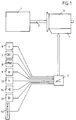
- Fig. 1 shows an automatic transmission 3, which is connected to a motor 1 through a drive shaft 2.
- the automatic transmission 3 contains clutches, not shown, which are actuated by electromagnetic valves, not shown, which are contained in a hydraulic control unit 4.
- electromagnetic pressure regulators are also located in the hydraulic control unit 4 .
- the electromagnetic valves and electromagnetic pressure regulators are controlled by an electronic control unit 5.
- the electronic control unit 5 contains the usual components of a microprocessor system, such as input and output part, main memory and arithmetic unit.
- Input variables for the electronic control unit 5 are a vehicle speed 6, a throttle valve signal 7, an engine speed 8, an engine torque 9 or a signal from which the engine torque can be calculated, e.g. B. the injection time, four wheel speeds 10, a steering angle 11, a signal from a brake light switch or brake pressure switch 12, the signal from a driving position switch 13 and the signal of a kick-down switch, not shown.
- the shift map 31 is selected by the two parameters K1, the driving activity, and the second parameter K2, the driving state.
- Input signals for the parameter K1 are an engine speed 8, an engine torque 9, four wheel speeds 10, the signal from a brake light switch 12 or brake pressure switch and the signal from a driving position switch 13.
- the engine speed 8 is digitally filtered 14.
- the filtered Engine speed is weighted as a function of gear via a map 19 and converted into a first value W1.
- the engine torque 9 is digitally filtered 15 and a second, weighted value W2 is determined therefrom via a map 20.
- a curve radius is calculated from the four wheel speeds 10 by forming the difference. The curve radius can also be calculated from a steering angle 11.
- the curve radius is digitally filtered 16 and weighted via a characteristic map 21 and converted into a third value W3.
- the brake light or brake pressure signal 12 is used for a time measurement, the braking activity.
- the time measurement begins with a change in vehicle acceleration from train to push. It ends when the driver applies the brake and the brake light signal is set or the brake pressure exceeds a setpoint.
- the braking activity is digitally filtered 17.
- the output variable of the digital filter 17 is weighted via a map 22 and converted into a fourth value W4.
- the signal from a driving position switch 13 is fed to a summer 18.
- the number of changes in driving position is added in summer 18.
- the counter content is reduced with a fixed timing, e.g. B.
- the characteristic curve 26 is assigned a first characteristic variable K1, the driving activity, to these values.
- the parameter K1 can assume an amount between 1 and 5.
- a low value means a consumption-optimized driving style
- a high value means a performance-optimized driving style.
- the characteristic curve 26 is subject to hysteresis. This avoids that with small changes in the input variables, the parameter K1 constantly oscillates back and forth.
- the input variables for the second parameter K2 are the driving conditions city traffic 27, trailer operation 28 and ascent 29.
- the prerequisite for the driving status of city traffic 27 is that the vehicle speed is below a generally legal speed limit within closed towns. Below this speed range, the number of starts, braking and load changes are counted. A load change is a change in the acceleration of the vehicle from train to thrust, and vice versa. If the total exceeds a first limit value, the driving condition city traffic is set. As a protection against overflow, the total is reduced with a fixed timing. This happens e.g. B. by subtracting a fixed amount or by multiplying the counter content by a factor ⁇ 1. The driving state city traffic 27 is reset as soon as the total falls below a second limit value.
- the driving states of trailer operation 28 and ascent 29 are explained in connection with FIG. 3.
- the three driving states 27 to 29 are input variables of an evaluation table 30.
- the input variables are logically linked to one another via the evaluation table 30.
- Eight input combinations for the evaluation table 30 result from the three driving states 27 to 29.
- four possible output states of the second characteristic variable K2 are assigned to the eight combinations.
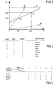
- One embodiment of the evaluation table 30 is shown in FIG. 4.
- FIG. 3 shows an exemplary embodiment according to which a distinction is made between increased driving resistance in mountain travel and / or trailer operation.
- the driving resistance is calculated in a stationary driving condition.
- a steady-state driving condition exists when the vehicle speed is greater than a limit, e.g. B. 10 km / h, the brake is not applied and outside of circuits.
- a limit e.g. B. 10 km / h
- an excess driving force is calculated.
- the excess driving force is composed of the actual driving force of the motor minus a sum of different driving resistance forces on the plane.
- the sum of the driving resistance forces is calculated from the transmission, rolling, air and acceleration resistance forces.
- the individual resistance forces are composed of vehicle-specific constants and the vehicle speed 6 at time t1.
- the engine torque can be present as real information in an electronic control unit 5, e.g. B. from an engine control, or it can be calculated.
- the engine torque calculation is done in a known manner in that the electronic control unit 5 from an engine speed signal 8 and a signal proportional to the injection time is calculated via a map.
- the excess driving force at time tl gives point A with the coordinates a (1) and dF (1).
- the excess driving force is then calculated in the same way at a second point in time t2. This gives the point B with the coordinates a (2) and dF (2).
- the two points A and B are connected by a mathematical function.
- a straight line is shown.
- the slope of the straight line is synonymous with the vehicle mass.
- the coefficients obtained in this way are checked for plausibility.
- the range of the minimum and maximum slope of the straight line is determined by the vehicle mass.
- the vehicle's unladen weight is the lower limit, broken line 32.
- the permissible total weight of the vehicle plus the maximum permissible trailer load forms an upper limit, broken line 33.
- the lower limit is formed by the abscissa.
- a maximum possible climbing performance of the vehicle forms the upper limit, dash-dotted line 34.
- FIG. 5 shows an exemplary embodiment according to which a shift map 31 is selected from five possible ones.
- Input variables are a first parameter K1, the driving activity, and a second parameter K2, the driving state.
- the first parameter K1 can assume values from 1 to 5.
- the driving state is divided into the driving states city traffic, normal operation, trailer operation and ascent.
- the shift maps 1 to 5 assigned to the two parameters include the range from consumption-optimized to performance-optimized driving.
Landscapes
- Engineering & Computer Science (AREA)
- General Engineering & Computer Science (AREA)
- Mechanical Engineering (AREA)
- Automation & Control Theory (AREA)
- Transportation (AREA)
- Physics & Mathematics (AREA)
- Mathematical Physics (AREA)
- Control Of Transmission Device (AREA)
Description
- Die Erfindung betrifft ein Verfahren zur Steuerung eines automatischen Schaltgetriebes nach dem Oberbegriff des ersten bzw. vierten Anspruchs.
- Bei einem automatischen Schaltgetriebe wird eine Schaltung ausgelöst, wenn eine Schaltkennlinie überschritten wird. Die Schaltkennlinien sind z. B. eine Funktion einer Fahrzeuggeschwindigkeit und einer Stellung der Drosselklappe. Üblicherweise kann der Fahrer aus drei Schaltprogrammen auswählen, z. B. durch Tastendruck.
- Aus der DE 39 22 051 A1 ein Verfahren zur Steuerung eines automatischen Schaltgetriebes bekannt, bei dem aus den aktuellen Fahrzeug-Parametern eine erste Kenngröße, die Fahraktivität, bestimmt wird. Die aktuellen Fahrzeug-Parameter sind: eine Motordrehzahl, eine Drosselklappenstellung, eine Querbeschleunigung, eine Fahrzeuggeschwindigkeit und, hieraus abgeleitet, die Längs-Beschleunigung bzw. Längs-Verzögerung. Die Fahraktivität wählt aus fünf Schaltprogrammen eines aus.
- Aus der EP-A-0 391 387 ist ein Verfahren bekannt, bei dem aus verschiedenen Fahr-Parametern, Gaspedalaktivität, Beschleunigung und Schaltaktivität, eine erste Kenngröße für das Verhalten des Fahrers und eine zweite Kenngröße für den Stadtbetrieb ermittelt wird.
- Ausgehend vom zuvor beschriebenen Stand der Technik hat die Erfindung zur Aufgabe, diesen weiterzuentwickeln.
- Eine erste Lösung der Aufgabe besteht darin, daß eine erste Kenngröße, die Fahraktivität, und eine zweite Kenngröße miteinander verknüpft werden, um ein Schaltprogramm aus einer Mehrzahl von möglichen Schaltprogrammen auszuwählen, wobei der Fahrzustand Stadtverkehr gesetzt wird, sobald eine Summe einen ersten Grenzwert überschreitet. Die Summe wird hierbei aus der Zahl der Anfahrvorgänge, Bremsvorgänge und Lastwechsel bestimmt, wobei die Summe periodisch durch Subtraktion eines festen Betrages bis zu einer minimalen Untergrenze von Null verringert wird. Alternativ hierzu kann die Summe durch Multiplikation mit einem Faktor < 1 ebenfalls verringert werden.
- In einer Ausgestaltung hierzu wird vorgeschlagen, daß der Fahrzustand Stadtverkehr zurückgesetzt wird, sobald die Summe einen zweiten Grenzwert unterschreitet.
- In einer weiteren Ausgestaltung wird vorgeschlagen, daß die Summierung nur unterhalb einer allgemein gesetzlichen Geschwindigkeitsbegrenzung innerhalb geschlossener Ortschaften erfolgt.
- Die erste erfindungsgemäße Lösung und deren Ausgestaltung bieten den Vorteil, daß der Verbrauch optimiert werden kann, da im Stadtverkehr bei leistungsstarken Motoren nicht immer die volle Motorleistung erforderlich ist. Eine Optimierung des Verbrauchs kann z. B. dadurch erzielt werden, daß das Fahrzeug im 2. Gang anfährt. Hierdurch wird ebenfalls die Kriechneigung verringert. Eine zusätzliche Maßnahme zur Verbrauchsminderung ist eine Zylinderabschaltung.
- Die zweite Kenngröße K2 wird aus den Fahrzuständen Stadtverkehr, Bergfahrt und Hängerbetrieb über eine Bewertungstabelle bestimmt. Beim gleichzeitigen Auftreten zweier Fahrzustände wird einer priorisiert. So wird z. B. bei Stadtverkehr gleichzeitig mit Hängerbetrieb der Fahrzustand Hängerbetrieb als zweite Kenngröße gesetzt.
- Eine zweite Lösung der Aufgabe besteht gemäß Anspruch 4 darin, daß zur Unterscheidung der Fahrzustände Bergfahrt und Hängerbetrieb zwei Bereiche vorgesehen sind. Gemäß Anspruch 5 wird die Untergrenze des ersten Bereichs durch das Fahrzeug-Leergewicht und die Obergrenze durch das zulässige Gesamtgewicht des Fahrzeugs plus maximal zulässige Anhängelast gebildet.
Gemäß Anspruch 6 wird die Untergrenze des zweiten Bereichs durch eine Steigung von Null oder nahezu Null Prozent gebildet und die Obergrenze durch die maximal mögliche Steigleistung des Fahrzeugs.
Die zweite Lösung und deren Ausgestaltung bieten den Vorteil, daß nicht nur erhöhter Fahrwiderstand erkannt, sondern erhöhter Fahrwiderstand zusätzlich in Bergfahrt und/ oder Hängerbetrieb unterschieden wird. Hierdurch kann man durch unterschiedliche Schaltprogramme gezielter reagieren. Bei Bergfahrt schaltet das Getriebe in die nächsthöhere Gangstufe bei höheren Fahrzeuggeschwindigkeiten. Dadurch werden bei kleinen Laststellungen Pendelschaltungen verhindert. Eine Pendelschaltung tritt dann auf, wenn bei konstanter Laststellung die Zugkraft des Motors nach einer Hochschaltung geringer ist als die Summe der Fahrwiderstandskräfte. Das Fahrzeug beschleunigt nicht mehr, die Fahrzeuggeschwindigkeit sinkt.
Diese sinkt so lange, bis eine Schaltkennlinie für eine Rückschaltung überschritten wird. Das Getriebe schaltet in die nächstniedere Gangstufe. Da die Zugkraft in dieser Gangstufe größer ist als die Fahrwiderstandskräfte, beschleunigt das Fahrzeug wieder. Es beschleunigt so lange, bis erneut die Schaltkennlinie für die Hochschaltung überschritten wird. Dieses Pendeln zwischen den Gängen wird als unangenehm empfunden.
Beim Hängerbetrieb wird die Hysterese zwischen den Hochschalt- und Rückschaltkennlinien vergrößert. Von Vorteil hierbei ist, daß zum einen sich dadurch das Beschleunigungsverhalten verbessert und zum anderen sich die Schiebewirkung des Hängers nach der Schaltung in eine niedere Gangstufe verringert. - In der Zeichnung ist ein Ausführungsbeispiel des Steuerungsverfahrens dargestellt. Es zeigen:
- Fig. 1
- ein Systemschaubild eines automatischen Schaltgetriebes;
- Fig. 2
- ein Blockschaltbild zur Auswahl eines Schaltkennfeldes;
- Fig. 3
- ein Diagramm zur Ermittlung der Fahrzustände Hänger und/oder Bergfahrt;
- Fig. 4
- eine Bewertungstabelle und
- Fig. 5
- ein Schaltkennfeld.
- Fig. 1 zeigt ein automatisches Schaltgetriebe 3, das mit einem Motor 1 durch eine Antriebswelle 2 verbunden ist. Das automatische Schaltgetriebe 3 enthält nicht dargestellte Kupplungen, die durch nicht dargestellte, elektromagnetische Ventile betätigt werden, welche in einem hydraulischen Steuergerät 4 enthalten sind. Ebenfalls in dem hydraulischen Steuergerät 4 befinden sich nicht dargestellte elektromagnetische Druckregler. Die elektromagnetischen Ventile und elektromagnetischen Druckregler werden von einem elektronischen Steuergerät 5 angesteuert. Das elektronische Steuergerät 5 enthält die üblichen Bestandteile eines Mikroprozessor-Systems, wie Eingabe- und Ausgabeteil, Arbeitsspeicher und Recheneinheit.
Eingangsgrößen für das elektronische Steuergerät 5 sind eine Fahrzeuggeschwindigkeit 6, ein Drosselklappensignal 7, eine Motordrehzahl 8, ein Motormoment 9 oder ein Signal, aus dem das Motormoment berechnet werden kann, z. B. die Einspritzzeit, vier Raddrehzahlen 10, ein Lenkwinkel 11, ein Signal von einem Bremslichtschalter oder Bremsdruckschalter 12, das Signal von einem Fahrpositionsschalter 13 und das Signal eines nicht dargestellten Kick-down-Schalters. - In Fig. 2 ist ein Blockschaltbild zur Auswahl eines Schaltkennfeldes 31 dargestellt. Das Schaltkennfeld 31 wird durch die beiden Kenngrößen K1, die Fahraktivität, und die zweite Kenngröße K2, den Fahrzustand, ausgewählt. Eingangssignale für die Kenngröße K1 sind eine Motordrehzahl 8, ein Motormoment 9, vier Raddrehzahlen 10, das Signal von einem Bremslichtschalter 12 oder Bremsdruckschalter und das Signal von einem Fahrpositionsschalter 13. Die Motordrehzahl 8 wird digital gefiltert 14. Die gefilterte Motordrehzahl wird über ein Kennfeld 19 gangabhängig gewichtet und in einen ersten Wert W1 gewandelt. Das Motoroment 9 wird digital gefiltert 15 und daraus über ein Kennfeld 20 ein zweiter, gewichteter Wert W2 bestimmt. Aus den vier Raddrehzahlen 10 wird durch Differenzbildung ein Kurvenradius berechnet. Der Kurvenradius kann ebenfalls berechnet werden aus einem Lenkwinkel 11. Der Kurvenradius wird digital gefilter 16 und über ein Kennfeld 21 gewichtet und in einen dritten Wert W3 gewandelt. Das Bremslicht- oder Bremsdrucksignal 12 wird zu einer Zeitmessung, der Bremsaktivität, verwendet. Die Zeitmessung beginnt mit einem Beschleunigungswechsel des Fahrzeugs von Zug nach Schub.
Sie endet, wenn der Fahrer die Bremse betätigt und das Bremslichtsignal gesetzt wird oder der Bremsdruck einen Sollwert überschreitet.
Die Bremsaktivität wird digital gefiltert 17. Die Ausgangsgröße des digitalen Filters 17 wird über ein Kennfeld 22 gewichtet und in einen vierten Wert W4 gewandelt. Das Signal eines Fahrpositionsschalters 13 wird einem Summierer 18 zugeführt. Im Summierer 18 wird die Anzahl der Fahrpositionsänderungen addiert. Der Zählerinhalt wird mit einem festen Zeittakt verringert, z. B. indem ein fester Betrag subtrahiert wird oder indem der Zählerinhalt mit einem Faktor < 1 multipliziert wird. Der Zählerstand wird über ein Kennfeld 23 gewichtet und in einen Wert W5 gewandelt.
Der Betrag der Werte W1 bis W5 liegt zwischen 0 und 1. Aus den Werten W1 bis W5 wird im Funktionsblock 24 der Maximalwert ausgewählt und anschließend gefiltert 25. Ausgangsgröße des Filters 25 ist ein Wert zwischen 0 und 1. Über die Kennlinie 26 wird diesen Werten eine erste Kenngröße K1, die Fahraktivität, zugeordnet. Die Kenngröße K1 kann einen Betrag zwischen 1 und 5 annehmen. Ein geringer Wert bedeutet eine verbrauchsoptimierte Fahrweise, ein hoher Wert bedeutet eine leistungsoptimierte Fahrweise. Die Kennlinie 26 ist hysteresebehaftet. Dadurch wird vermieden, daß bei geringen Änderungen der Eingangsgrößen die Kenngröße K1 ständig hin und her pendelt. - Eingangsgrößen für die zweite Kenngröße K2 sind die Fahrzustände Stadtverkehr 27, Hängerbetrieb 28 und Bergfahrt 29.
Eingangsvoraussetzung für den Fahrzustand Stadtverkehr 27 ist, daß die Fahrzeuggeschwindigkeit unterhalb einer allgemein gesetzlichen Geschwindigkeitsbegrenzung innerhalb geschlossener Ortschaften ist. Unterhalb dieses Geschwindigkeitsbereichs wird die Zahl der Anfahrvorgänge, der Bremsvorgänge und Lastwechsel gezählt. Ein Lastwechsel ist ein Wechsel in der Beschleunigung des Fahrzeugs von Zug nach Schub, auch umgekehrt. Überschreitet die Summe einen ersten Grenzwert, so wird der Fahrzustand Stadtverkehr gesetzt. Als Schutz gegen Überlauf wird die Summe mit einem festen Zeittakt verringert. Dies geschieht z. B. dadurch, daß ein fester Betrag subtrahiert wird oder indem der Zählerinhalt mit einem Faktor < 1 multipliziert wird. Der Fahrzustand Stadtverkehr 27 wird zurückgesetzt, sobald die Summe einen zweiten Grenzwert unterschreitet. Die Fahrzustände Hängerbetrieb 28 und Bergfahrt 29 werden im Zusammenhang mit Fig. 3 erklärt. - Die drei Fahrzustände 27 bis 29 sind Eingangsgrößen einer Bewertungstabelle 30. Über die Bewertungstabelle 30 werden die Eingangsgrößen logisch miteinander verknüpft. Aus den drei Fahrzuständen 27 bis 29 ergeben sich acht Eingangskombinationen für die Bewertungstabelle 30. In der Bewertungstabelle 30 sind den acht Kombinationen vier mögliche Ausgangszustände der zweiten Kenngröße K2 zugeordnet. Eine Ausführungsform der Bewertungstabelle 30 ist in Fig. 4 dargestellt.
- In Fig. 3 ist ein Ausführungsbeispiel dargestellt, nach dem erhöhter Fahrwiderstand unterschieden wird in Bergfahrt und/oder Hängerbetrieb. Bei den bisher bekannten Verfahren wird lediglich erhöhter Fahrwiderstand ermittelt. Der Fahrwiderstand wird bei einem stationären Fahrzustand berechnet. Ein stationärer Fahrzustand liegt vor, wenn die Fahrzeuggeschwindigkeit größer einem Grenzwert ist, z. B. 10 km/h, die Bremse nicht betätigt ist und außerhalb von Schaltungen. Zu einem ersten Zeitpunkt tl wird eine Überschuß-Antriebskraft berechnet. Die Überschuß-Antriebskraft setzt sich zusammen aus der tatsächlichen Antriebskraft des Motors minus einer Summe aus verschiedenen Fahrwiderstandskräften auf der Ebene. Die Summe der Fahrwiderstandskräfte berechnet sich aus Getriebe-, Roll-, Luft- und Beschleunigungswiderstandskraft. Die Einzelwiderstandskräfte setzen sich zusammen aus fahrzeugspezifischen Konstanten und der Fahrzeuggeschwindigkeit 6 zum Zeitpunkt tl. Das Motormoment kann als echte Information in einem elektronischen Steuergerät 5 vorliegen, z. B. aus einer Motorsteuerung, oder es kann berechnet werden. Die Motor-Momentberechnung geschieht in bekannter Art dadurch, daß das elektronische Steuergerät 5 aus einem Motordrehzahlsignal 8 und einem zur Einspritzzeit proportionalen Signal über ein Kennfeld das Moment berechnet. Die Überschußantriebskraft zum Zeitpunkt tl ergibt den Punkt A mit den Koordinaten a (1) und dF (1). Danach wird die Überschuß-Antriebskraft zu einem zweiten Zeitpunkt t2 in gleicher Art berechnet. Dies ergibt den Punkt B mit den Koordinaten a (2) und dF (2).
Die beiden Punkte A und B werden durch eine mathematische Funktion miteinander verbunden. Dargestellt ist eine Gerade. Die Steigung der Geraden ist gleichbedeutend mit der Fahrzeugmasse. Der Ordinatenwert an der Stelle a = 0 ist gleichbedeutend mit dem Produkt aus Fahrzeugmasse mal Erdbeschleunigung mal Sinus des Fahrzeugsteigungswinkels. - Die derart gewonnenen Koeffizienten werden auf Plausibilität geprüft. Der Bereich der minimalen und maximalen Steigung der Geraden wird durch die Fahrzeugmasse festgelegt. Das Fahrzeug-Leergewicht ist die Untergrenze, unterbrochene Linie 32. Das zulässige Gesamtgewicht des Fahrzeugs plus maximal zulässiger Anhängelast bildet eine Obergrenze, unterbrochene Linie 33. Der Bereich des minimalen und maximalen Ordinatenwerts an der Stelle a = 0 wird durch die Steigleistung des Fahrzeugs festgelegt. Eine Steigung von Null oder nahezu Null Prozent bildet eine Untergrenze. Die Untergrenze wird durch die Abszisse gebildet. Eine maximal mögliche Steigleistung des Fahrzeugs bildet die Obergrenze, strichpunktierte Linie 34.
- Eine Anpassung der aus der Geraden-Steigung ermittelten Masse mit der tatsächlichen Masse wird über einen Korrekturfaktor erzielt. Der Korrekturfaktor wird aus dem Vergleich zweier aufeinanderfolgender Masseberechnungen gewonnen. Dies ist zulässig, da die Massenverhältnisse sich während der Fahrt nicht ändern.
Danach wird während des Fahrbetriebs (Zündung gleich "An") nur noch die Fahrzeugsteigung geprüft. - In Fig. 5 ist ein Ausführungsbeispiel dargestellt, nach dem ein Schaltkennfeld 31 aus fünf möglichen ausgewählt wird. Eingangsgrößen sind eine erste Kenngröße K1, die Fahraktivität, und eine zweite Kenngröße K2, der Fahrzustand. Die erste Kenngröße K1 kann Werte von 1 bis 5 annehmen. Der Fahrzustand gliedert sich auf in die Fahrzustände Stadtverkehr, Normalbetrieb, Hängerbetrieb und Bergfahrt. Die den beiden Kenngrößen zugeordneten Schaltkennfelder 1 bis 5 umfassen den Bereich von verbrauchsoptimierter bis zu leistungsoptimierter Fahrweise.
-
- 1
- Motor
- 2
- Antriebswelle
- 3
- automatisches Schaltgetriebe
- 4
- hydraulisches Steuergerät
- 5
- elektronisches Steuergerät
- 6
- Fahrzeuggeschwindigkeitssignal
- 7
- Drosselklappensignal
- 8
- Motordrehzahlsignal
- 9
- Motormoment
- 10
- vier Raddrehzahlen
- 11
- Lenkwinkel
- 12
- Bremslichtsignal
- 13
- Fahrpositionsschalter
- 14
- Digitalfilter
- 15
- Digitalfilter
- 16
- Digitalfilter
- 17
- Digitalfilter
- 18
- Summierer
- 19
- Kennfeld
- 20
- Kennfeld
- 21
- Kennfeld
- 22
- Kennfeld
- 23
- Kennfeld
- 24
- Funktionsblock
- 25
- Gesamt-Filter
- 26
- Kennfeld
- 27
- Stadtverkehr
- 28
- Hängerbetrieb
- 29
- Bergfahrt
- 30
- Bewertungstabelle
- 31
- Schaltkennfeld
- 32
- Untergrenze, Fahrzeugleergewicht
- 33
- Obergrenze,
zulässiges Gesamtgewicht + maximal zulässige Anhängelast - 34
- maximal mögliche Steigleistung
- K1
- erste Kenngröße, Fahraktivität
- K2
- zweite Kenngröße, Fahrzustand
Claims (11)
- Verfahren zur Steuerung eines automatischen Schaltgetriebes (3) mit Kupplungen, die durch ein elektronisches Steuergerät (5) gesteuert oder geregelt werden, das elektronische Steuergerät (5) Sensorsignale (6 bis 13) erhält, aus den Sensorsignalen (6 bis 13) eine erste Kenngröße (K1) für eine Fahraktivität und eine zweite Kenngröße (K2) für einen Fahrzustand bestimmt, die erste Kenngröße (K1) aus den gewichteten Größen Wählhebelaktivität, Motor-Momentüberschuß, Kurvenradius und Bremsaktivität gebildet wird und die zweite Kenngröße (K2) über eine Bewertungstabelle (30) aus den Fahrzuständen Stadtverkehr (27), Hängerbetrieb (28) und Bergfahrt (29) gebildet wird, dadurch gekennzeichnet, daß die erste Kenngröße (K1) und die zweite Kenngröße (K2) miteinander verknüpft werden, um ein Schaltprogramm aus einer Mehrzahl von möglichen Schaltprogrammen, Schaltkennfeld (31), auszuwählen, wobei die Zahl von Anfahrvorgängen, Bremsvorgängen und Lastwechsel summiert werden, die Summe periodisch durch Subtraktion eines festen Betrages verringert wird bis zu einer minimalen Untergrenze von Null oder durch Multiplikation der Summe mit einem Faktor < 1 und der Fahrzustand Stadtverkehr (28) gesetzt wird, sobald die Summe einen ersten Grenzwert überschreitet.
- Verfahren nach Anspruch 1, dadurch gekennzeichnet, daß der Fahrzustand Stadtverkehr (27) zurückgesetzt wird, sobald eine Summe einen zweiten Grenzwert unterschreitet.
- Verfahren nach Anspruch 1, dadurch gekennzeichnet, daß die Summierung nur unterhalb einer allgemein gesetzlichen Geschwindigkeitsbegrenzung innerhalb geschlossener Ortschaften erfolgt.
- Verfahren nach dem Oberbegriff von Anspruch 1, dadurch gekennzeichnet, daß zur Unterscheidung der Fahrzustände Bergfahrt (29) und Hängerbetrieb (28) zwei Bereiche vorgesehen sind.
- Verfahren nach Anspruch 4, dadurch gekennzeichnet, daß die Untergrenze (32) des ersten Bereichs durch das Fahrzeug-Leergewicht gebildet wird und die Obergrenze (33) durch das zulässige Gesamtgewicht des Fahrzeugs plus maximal zulässiger Anhängelast.
- Verfahren nach Anspruch 4, dadurch gekennzeichnet, daß die Untergrenze des zweiten Bereichs durch eine Steigung von Null oder nahezu Null Prozent gebildet wird und die Obergrenze (34) durch die maximal mögliche Steigleistung des Fahrzeugs.
- Verfahren nach Anspruch 4, dadurch gekennzeichnet, daß im stationären Zustand zum Zeitpunkt tl ein erster Wert und zum Zeitpunkt t2 ein zweiter Wert einer Überschuß-Antriebskraft ermittelt wird.
- Verfahren nach Anspruch 7, dadurch gekennzeichnet, daß die Überschuß-Antriebskraft berechnet wird aus einer Differenz momentaner Antriebskraft des Motors minus einer Summe der Fahrwiderstandskräfte auf der Ebene, gebildet aus Getriebe-, Roll-, Luft- und Beschleunigungswiderstandskraft.
- Verfahren nach Anspruch 7, dadurch gekennzeichnet, daß der Wert der Überschuß-Antriebskraft demjenigen Bereich zugeordnet wird, in dessen betragsmäßigen Grenzen er liegt.
- Verfahren nach Anspruch 7, dadurch gekennzeichnet, daß eine Gerade beide Werte der Überschuß-Antriebskraft miteinander verbindet.
- Verfahren nach Anspruch 10, dadurch gekennzeichnet, daß anhand der Koeffizienten der Geraden ein bestimmter Fahrzustand identifiziert wird.
Applications Claiming Priority (3)
| Application Number | Priority Date | Filing Date | Title |
|---|---|---|---|
| DE4312717 | 1993-04-20 | ||
| DE4312717A DE4312717A1 (de) | 1993-04-20 | 1993-04-20 | Verfahren zur steuerung eines automatischen schaltgetriebes |
| PCT/EP1994/001189 WO1994024464A2 (de) | 1993-04-20 | 1994-04-18 | Verfahren zur steuerung eines automatischen schaltgetriebes |
Publications (2)
| Publication Number | Publication Date |
|---|---|
| EP0694138A1 EP0694138A1 (de) | 1996-01-31 |
| EP0694138B1 true EP0694138B1 (de) | 1997-06-25 |
Family
ID=6485804
Family Applications (1)
| Application Number | Title | Priority Date | Filing Date |
|---|---|---|---|
| EP94914393A Expired - Lifetime EP0694138B1 (de) | 1993-04-20 | 1994-04-18 | Verfahren zur steuerung eines automatischen schaltgetriebes |
Country Status (6)
| Country | Link |
|---|---|
| US (1) | US5748472A (de) |
| EP (1) | EP0694138B1 (de) |
| JP (1) | JP3264931B2 (de) |
| KR (1) | KR100316251B1 (de) |
| DE (2) | DE4312717A1 (de) |
| WO (1) | WO1994024464A2 (de) |
Cited By (2)
| Publication number | Priority date | Publication date | Assignee | Title |
|---|---|---|---|---|
| WO2000025045A1 (de) | 1998-10-24 | 2000-05-04 | Zf Friedrichshafen Ag | Stadtfahr-betriebsverfahren für ein elektronisch gesteuertes, automatisches schaltgetriebe |
| US6571164B1 (en) | 1999-03-13 | 2003-05-27 | Zf Friedrichshafen Ag | Method for controlling an automatic gearbox involving determination of a transverse acceleration value |
Families Citing this family (34)
| Publication number | Priority date | Publication date | Assignee | Title |
|---|---|---|---|---|
| DE4426153A1 (de) * | 1994-07-23 | 1996-01-25 | Zahnradfabrik Friedrichshafen | Steuersystem zum Verändern der Übersetzung eines automatischen Getriebes |
| JP3663677B2 (ja) * | 1995-07-06 | 2005-06-22 | アイシン・エィ・ダブリュ株式会社 | 車両用自動変速機の制御装置 |
| DE19528625A1 (de) * | 1995-08-04 | 1997-02-06 | Bosch Gmbh Robert | System zur Bestimmung der Übersetzungsänderung bei einem Automatikgetriebe |
| FR2741931B1 (fr) * | 1995-11-30 | 1998-01-09 | Renault | Procede de commande d'une transmission automatique en fonction du style de conduite du conducteur |
| GB9602731D0 (en) * | 1996-02-10 | 1996-04-10 | Ap Kongsberg Holdings Ltd | Transmission control systems |
| DE19618811A1 (de) * | 1996-05-10 | 1997-11-13 | Zahnradfabrik Friedrichshafen | Verfahren zur Bewertung eines Anfahrvorganges bei einem Automatgetriebe |
| DE19618805A1 (de) * | 1996-05-10 | 1997-11-13 | Zahnradfabrik Friedrichshafen | Verfahren zur Bewertung einer Kurvenfahrt bei einem Automatgetriebe |
| DE19618804A1 (de) * | 1996-05-10 | 1997-11-13 | Zahnradfabrik Friedrichshafen | Verfahren zur Bewertung eines Straßenverlaufes bei einem Automatgetriebe |
| DE19624061A1 (de) * | 1996-06-17 | 1997-12-18 | Opel Adam Ag | Verfahren zur Steuerung des Gangwechsels eines Kraftfahrzeug-Automatikgetriebes |
| DE19625935A1 (de) * | 1996-06-28 | 1998-01-08 | Bosch Gmbh Robert | System zur Einstellung einer Getriebeübersetzung |
| JP3953145B2 (ja) * | 1997-08-01 | 2007-08-08 | アイシン・エィ・ダブリュ株式会社 | 車両制御装置 |
| JP4010380B2 (ja) | 1997-08-08 | 2007-11-21 | アイシン・エィ・ダブリュ株式会社 | 車両制御装置及びプログラムを記録した記録媒体 |
| DE19744598B4 (de) * | 1997-10-09 | 2006-06-08 | Volkswagen Ag | Verfahren zum Steuern eines Automatikgetriebes eines Kraftfahrzeuges |
| DE19752623C2 (de) * | 1997-11-27 | 1999-11-25 | Siemens Ag | Steuerung für ein automatisches Kraftfahrzeuggetriebe |
| FR2775749B1 (fr) * | 1998-03-03 | 2000-05-05 | Renault | Procede de supervision adaptative de transmission automatique a evaluation multicritere floue |
| DE19814483C2 (de) * | 1998-04-01 | 2000-11-30 | Bosch Gmbh Robert | System zur Ermittlung einer Bestimmungsgröße |
| DE19849058A1 (de) * | 1998-10-24 | 2000-04-27 | Zahnradfabrik Friedrichshafen | Verfahren zur Steuerung einer Hochtemperatur-Betriebsart eines elektronisch gesteuerten, automatischen Schaltgetriebes |
| DE19932492B4 (de) * | 1999-07-12 | 2007-05-31 | Fraunhofer-Gesellschaft zur Förderung der angewandten Forschung e.V. | Verfahren zur Steuerung eines Automatikgetriebes für Kraftfahrzeuge |
| DE102004021801A1 (de) * | 2004-05-03 | 2005-12-01 | Zf Friedrichshafen Ag | Verfahren zur Steuerung eines automatisierten Schaltgetriebes |
| SE527413C2 (sv) * | 2004-07-02 | 2006-02-28 | Volvo Lastvagnar Ab | Motordrivet fordon med transmission |
| DE102005022314A1 (de) | 2005-05-10 | 2006-11-16 | Zf Friedrichshafen Ag | Verfahren zur Steuerung eines Getriebes eines Fahrzeugs |
| DE102005028551B4 (de) | 2005-06-21 | 2023-03-30 | Holger Albrecht | Steuerungseinrichtung und Verfahren für ein automatisches Getriebe |
| DE102005049710A1 (de) * | 2005-10-18 | 2007-04-26 | Zf Friedrichshafen Ag | Verfahren zur Beeinflussung eines automatisierten Schaltgetriebes unter Berücksichtigung des Fahrwiderstandes |
| JP4188360B2 (ja) * | 2005-10-31 | 2008-11-26 | 本田技研工業株式会社 | 自動変速機の変速制御装置 |
| US20070271017A1 (en) * | 2006-05-18 | 2007-11-22 | Farzad Samie | Weight dependent trailering switch |
| US7653469B2 (en) | 2006-07-25 | 2010-01-26 | Gm Global Technology Operations, Inc. | Automatic transmission shift point control system and method of use |
| DE102007015355A1 (de) | 2007-03-30 | 2008-10-02 | Zf Friedrichshafen Ag | Steuerungsvorrichtung eines automatisierten Stufenschaltgetriebes |
| DE102007016761A1 (de) * | 2007-04-07 | 2008-10-09 | Zf Friedrichshafen Ag | Verfahren und System zum Steuern und/oder Regeln eines mehrstufigen Automatgetriebes eines Fahrzeuges |
| US8260511B2 (en) * | 2007-11-03 | 2012-09-04 | GM Global Technology Operations LLC | Method for stabilization of mode and fixed gear for a hybrid powertrain system |
| US8433486B2 (en) * | 2007-11-07 | 2013-04-30 | GM Global Technology Operations LLC | Method and apparatus to determine a preferred operating point for an engine of a powertrain system using an iterative search |
| JP4591588B2 (ja) * | 2008-09-30 | 2010-12-01 | マツダ株式会社 | 電動車両のモータ制御方法および電動車両用駆動装置 |
| DE102012223512A1 (de) | 2012-12-18 | 2013-09-12 | Zf Friedrichshafen Ag | Verfahren zum Betreiben eines Automatikgetriebes |
| DE102015225497A1 (de) * | 2015-12-16 | 2017-06-22 | Zf Friedrichshafen Ag | Verfahren zum Verhindern von unerwünschten Fahrsituationen bei einem Fahrzeug |
| GB2551511B (en) * | 2016-06-20 | 2019-06-19 | Trakm8 Ltd | Detection of tailgating situations |
Citations (1)
| Publication number | Priority date | Publication date | Assignee | Title |
|---|---|---|---|---|
| EP0391387A2 (de) * | 1989-04-04 | 1990-10-10 | Japan Electronic Control Systems Co., Ltd. | Fahrzustandserfassungssystem für ein Kraftfahrzeug und Schaltungssteuerung für ein automatisches Kraftfahrzeuggetriebe, welches die Ergebnisse aus der Fahrzustandserfassung verwendet |
Family Cites Families (18)
| Publication number | Priority date | Publication date | Assignee | Title |
|---|---|---|---|---|
| US3684066A (en) * | 1969-10-08 | 1972-08-15 | Toyota Motor Co Ltd | Automatic shift control system for automatic transmission |
| GB1431186A (en) * | 1973-03-23 | 1976-04-07 | Delectronique Et Dautomatique | Control system |
| US4630508A (en) * | 1983-03-28 | 1986-12-23 | Wabco Westinghouse Fahrzeugbremsen Gmbh | Method and apparatus to determine constant speed torque on an engine |
| DE3314800A1 (de) * | 1983-03-28 | 1984-10-04 | Wabco Westinghouse Fahrzeugbremsen GmbH, 3000 Hannover | Kontrolleinrichtung fuer ein von einer antriebsmaschine ueber ein abgestuftes getriebe angetriebenes fahrzeug |
| DE3311306A1 (de) * | 1983-03-28 | 1984-10-11 | Wabco Westinghouse Fahrzeugbremsen GmbH, 3000 Hannover | Kontrolleinrichtung fuer ein fahrzeug-getriebe zur feststellung des wirtschaftlichen fahrbereichs |
| US4584906A (en) * | 1983-04-26 | 1986-04-29 | Mazda Motor Corporation | Gear shift control for an automatic transmission of a vehicle |
| DE3703234A1 (de) * | 1987-02-04 | 1988-08-18 | Renk Ag | Steuerschaltung fuer eine zugmaschine |
| US4862854A (en) * | 1987-04-06 | 1989-09-05 | Mazda Motor Corporation | Control systems for vehicle engines |
| US5189621A (en) * | 1987-05-06 | 1993-02-23 | Hitachi, Ltd. | Electronic engine control apparatus |
| JPH01238748A (ja) * | 1988-03-17 | 1989-09-22 | Mitsubishi Electric Corp | 自動変速機の変速制御装置 |
| JPH07117151B2 (ja) * | 1988-04-20 | 1995-12-18 | 日産自動車株式会社 | 自動変速機の変速制御装置 |
| JP2701429B2 (ja) * | 1989-03-03 | 1998-01-21 | 三菱電機株式会社 | 自動変速機の制御装置 |
| DE3922051A1 (de) * | 1989-07-05 | 1991-01-24 | Porsche Ag | Verfahren und vorrichtung zur steuerung eines selbsttaetig schaltenden getriebes |
| EP0801252B1 (de) * | 1991-03-13 | 2003-09-10 | Mitsubishi Jidosha Kogyo Kabushiki Kaisha | Gangwechsel-Steuerverfahren für automatisches Fahrzeuggetriebe |
| JP2974440B2 (ja) * | 1991-03-22 | 1999-11-10 | 株式会社日立製作所 | 自動車総合制御装置 |
| EP0512596B1 (de) * | 1991-05-06 | 1996-02-07 | Delco Electronics Corporation | Verfahren zum Regeln der Gangänderungskennlinien für das automatische Getriebe eines Kraftfahrzeuges |
| US5474505A (en) * | 1991-06-21 | 1995-12-12 | Dr. Ing. H.C.F. Porsche Ag | Method for controlling an automatically operated motor vehicle transmission |
| DE4240762A1 (en) * | 1991-12-03 | 1993-06-09 | Hitachi, Ltd., Tokio/Tokyo, Jp | Automatic gearbox control for motor vehicle - uses vehicle wt. calculator, output torque estimator and stored gear setting tables to select gear taking into account required acceleration |
-
1993
- 1993-04-20 DE DE4312717A patent/DE4312717A1/de not_active Withdrawn
-
1994
- 1994-04-18 DE DE59403224T patent/DE59403224D1/de not_active Expired - Fee Related
- 1994-04-18 WO PCT/EP1994/001189 patent/WO1994024464A2/de not_active Ceased
- 1994-04-18 KR KR1019950704537A patent/KR100316251B1/ko not_active Expired - Fee Related
- 1994-04-18 EP EP94914393A patent/EP0694138B1/de not_active Expired - Lifetime
- 1994-04-18 US US08/549,843 patent/US5748472A/en not_active Expired - Fee Related
- 1994-04-18 JP JP52276094A patent/JP3264931B2/ja not_active Expired - Fee Related
Patent Citations (1)
| Publication number | Priority date | Publication date | Assignee | Title |
|---|---|---|---|---|
| EP0391387A2 (de) * | 1989-04-04 | 1990-10-10 | Japan Electronic Control Systems Co., Ltd. | Fahrzustandserfassungssystem für ein Kraftfahrzeug und Schaltungssteuerung für ein automatisches Kraftfahrzeuggetriebe, welches die Ergebnisse aus der Fahrzustandserfassung verwendet |
Cited By (3)
| Publication number | Priority date | Publication date | Assignee | Title |
|---|---|---|---|---|
| WO2000025045A1 (de) | 1998-10-24 | 2000-05-04 | Zf Friedrichshafen Ag | Stadtfahr-betriebsverfahren für ein elektronisch gesteuertes, automatisches schaltgetriebe |
| US6529813B1 (en) | 1998-10-24 | 2003-03-04 | Zf Friedrichshafen Ag | Urban driving operating method for an electronically controlled automatic gearbox |
| US6571164B1 (en) | 1999-03-13 | 2003-05-27 | Zf Friedrichshafen Ag | Method for controlling an automatic gearbox involving determination of a transverse acceleration value |
Also Published As
| Publication number | Publication date |
|---|---|
| DE59403224D1 (de) | 1997-07-31 |
| KR100316251B1 (ko) | 2002-04-24 |
| WO1994024464A3 (de) | 1994-12-22 |
| US5748472A (en) | 1998-05-05 |
| WO1994024464A2 (de) | 1994-10-27 |
| JP3264931B2 (ja) | 2002-03-11 |
| EP0694138A1 (de) | 1996-01-31 |
| KR960702081A (ko) | 1996-03-28 |
| DE4312717A1 (de) | 1993-11-04 |
| JPH08508811A (ja) | 1996-09-17 |
Similar Documents
| Publication | Publication Date | Title |
|---|---|---|
| WO1994024464A2 (de) | Verfahren zur steuerung eines automatischen schaltgetriebes | |
| EP0576703B1 (de) | Getriebesteuerung | |
| EP0739465B1 (de) | Steuerung für ein automatisches kraftfahrzeug-getriebe | |
| DE3341652C2 (de) | ||
| DE4440706C2 (de) | Verfahren und Vorrichtung zur streckenneigungsabhängigen Steuerung des Schaltpunktes eines Automatikgetriebes | |
| EP0156820B1 (de) | Verfahren und schaltungsvorrichtung zur ermittlung des verbrauchsoptimalen getriebeganges eines kraftfahrzeugantriebes | |
| DE19528625A1 (de) | System zur Bestimmung der Übersetzungsänderung bei einem Automatikgetriebe | |
| EP0638742A1 (de) | Steuerung für eine Einrichtung in einem Kraftfahrzeug, insbesondere für ein automatisches Getriebe | |
| EP0589910B1 (de) | Verfahren zur steuerung eines selbsttätig schaltenden getriebes eines kraftfahrzeugs | |
| DE10108036A1 (de) | Controller für Automatikgetriebe | |
| DE4204881C2 (de) | Verfahren und Vorrichtung zum Steuern eines automatischen Kfz-Getriebes | |
| DE19854254A1 (de) | Verfahren zur Steuerung eines Schaltvorganges in Automatikgetrieben | |
| EP1123475A1 (de) | Verfahren zur steuerung eines automatgetriebes eines kraftfahrzeuges bei einer spontanen gas-pedalrücknahme | |
| EP0634591B1 (de) | Verfahren und Vorrichtung zum Steuern eines automatischen Getriebes | |
| DE4337163A1 (de) | Steuerungseinrichtung zur selbsttätigen und fahrstreckenabhängigen Schaltung eines Automatikgetriebes | |
| DE4120566C2 (de) | Steuereinrichtung für ein selbsttätig schaltendes Getriebe eines Kraftfahrzeugs | |
| DE19600915A1 (de) | Verfahren zur Vorgabe der Übersetzung eines stufenlosen Getriebes | |
| DE4342204C2 (de) | Verfahren zur Steuerung der aus Motor und Getriebe bestehenden Antriebseinheit von Kraftfahrzeugen | |
| EP0622570B1 (de) | Steuerung für ein automatisches Kraftfahrzeug-Getriebe | |
| DE69809236T2 (de) | Verfahren zum steuern der zurückschaltungsgänge bei automatikgetrieben | |
| EP0916042A1 (de) | Verfahren zur vorgabe der übersetzung eines stufenlosen getriebes | |
| DE69805620T2 (de) | Steuerungsverfahren zum schalten eines automatikgetriebes | |
| EP1123472B1 (de) | Stadtfahr-betriebsverfahren für ein elektronisch gesteuertes, automatisches schaltgetriebe | |
| EP0626527B1 (de) | Steuerung für ein automatisches Getriebe in einem Kraftfahrzeug | |
| EP0583610A1 (de) | Verfahren zur Reduzierung des Abtriebsmoments bei Durchdrehneigung der angetriebenen Räder in Kraftfahrzeugen |
Legal Events
| Date | Code | Title | Description |
|---|---|---|---|
| PUAI | Public reference made under article 153(3) epc to a published international application that has entered the european phase |
Free format text: ORIGINAL CODE: 0009012 |
|
| 17P | Request for examination filed |
Effective date: 19951120 |
|
| AK | Designated contracting states |
Kind code of ref document: A1 Designated state(s): DE FR GB IT SE |
|
| 17Q | First examination report despatched |
Effective date: 19960429 |
|
| GRAG | Despatch of communication of intention to grant |
Free format text: ORIGINAL CODE: EPIDOS AGRA |
|
| GRAH | Despatch of communication of intention to grant a patent |
Free format text: ORIGINAL CODE: EPIDOS IGRA |
|
| ITF | It: translation for a ep patent filed | ||
| GRAH | Despatch of communication of intention to grant a patent |
Free format text: ORIGINAL CODE: EPIDOS IGRA |
|
| GRAA | (expected) grant |
Free format text: ORIGINAL CODE: 0009210 |
|
| AK | Designated contracting states |
Kind code of ref document: B1 Designated state(s): DE FR GB IT SE |
|
| GBT | Gb: translation of ep patent filed (gb section 77(6)(a)/1977) |
Effective date: 19970626 |
|
| REF | Corresponds to: |
Ref document number: 59403224 Country of ref document: DE Date of ref document: 19970731 |
|
| ET | Fr: translation filed | ||
| PLBE | No opposition filed within time limit |
Free format text: ORIGINAL CODE: 0009261 |
|
| STAA | Information on the status of an ep patent application or granted ep patent |
Free format text: STATUS: NO OPPOSITION FILED WITHIN TIME LIMIT |
|
| 26N | No opposition filed | ||
| PGFP | Annual fee paid to national office [announced via postgrant information from national office to epo] |
Ref country code: GB Payment date: 20000323 Year of fee payment: 7 |
|
| PGFP | Annual fee paid to national office [announced via postgrant information from national office to epo] |
Ref country code: SE Payment date: 20000420 Year of fee payment: 7 |
|
| PG25 | Lapsed in a contracting state [announced via postgrant information from national office to epo] |
Ref country code: GB Free format text: LAPSE BECAUSE OF NON-PAYMENT OF DUE FEES Effective date: 20010418 |
|
| PG25 | Lapsed in a contracting state [announced via postgrant information from national office to epo] |
Ref country code: SE Free format text: LAPSE BECAUSE OF NON-PAYMENT OF DUE FEES Effective date: 20010419 |
|
| EUG | Se: european patent has lapsed |
Ref document number: 94914393.7 |
|
| GBPC | Gb: european patent ceased through non-payment of renewal fee |
Effective date: 20010418 |
|
| PGFP | Annual fee paid to national office [announced via postgrant information from national office to epo] |
Ref country code: FR Payment date: 20030417 Year of fee payment: 10 |
|
| PG25 | Lapsed in a contracting state [announced via postgrant information from national office to epo] |
Ref country code: FR Free format text: LAPSE BECAUSE OF NON-PAYMENT OF DUE FEES Effective date: 20041231 |
|
| REG | Reference to a national code |
Ref country code: FR Ref legal event code: ST |
|
| PG25 | Lapsed in a contracting state [announced via postgrant information from national office to epo] |
Ref country code: IT Free format text: LAPSE BECAUSE OF NON-PAYMENT OF DUE FEES;WARNING: LAPSES OF ITALIAN PATENTS WITH EFFECTIVE DATE BEFORE 2007 MAY HAVE OCCURRED AT ANY TIME BEFORE 2007. THE CORRECT EFFECTIVE DATE MAY BE DIFFERENT FROM THE ONE RECORDED. Effective date: 20050418 |
|
| PGFP | Annual fee paid to national office [announced via postgrant information from national office to epo] |
Ref country code: DE Payment date: 20080424 Year of fee payment: 15 |
|
| PG25 | Lapsed in a contracting state [announced via postgrant information from national office to epo] |
Ref country code: DE Free format text: LAPSE BECAUSE OF NON-PAYMENT OF DUE FEES Effective date: 20091103 |