EP0693584A1 - Gleitführung und Antrieb für Kardenwanderdeckel - Google Patents
Gleitführung und Antrieb für Kardenwanderdeckel Download PDFInfo
- Publication number
- EP0693584A1 EP0693584A1 EP95201945A EP95201945A EP0693584A1 EP 0693584 A1 EP0693584 A1 EP 0693584A1 EP 95201945 A EP95201945 A EP 95201945A EP 95201945 A EP95201945 A EP 95201945A EP 0693584 A1 EP0693584 A1 EP 0693584A1
- Authority
- EP
- European Patent Office
- Prior art keywords
- flats
- flat
- guiding
- chain
- card
- Prior art date
- Legal status (The legal status is an assumption and is not a legal conclusion. Google has not performed a legal analysis and makes no representation as to the accuracy of the status listed.)
- Granted
Links
- 238000009960 carding Methods 0.000 title claims abstract description 19
- 230000008878 coupling Effects 0.000 claims abstract description 10
- 238000010168 coupling process Methods 0.000 claims abstract description 10
- 238000005859 coupling reaction Methods 0.000 claims abstract description 10
- 230000000694 effects Effects 0.000 claims description 3
- 230000005484 gravity Effects 0.000 claims description 3
- 230000014759 maintenance of location Effects 0.000 abstract description 2
- 239000000835 fiber Substances 0.000 description 4
- 230000002093 peripheral effect Effects 0.000 description 3
- 238000004140 cleaning Methods 0.000 description 2
- 239000002657 fibrous material Substances 0.000 description 2
- 238000003754 machining Methods 0.000 description 2
- 238000012423 maintenance Methods 0.000 description 2
- 238000000034 method Methods 0.000 description 2
- 230000004048 modification Effects 0.000 description 2
- 238000012986 modification Methods 0.000 description 2
- 230000008569 process Effects 0.000 description 2
- 230000009471 action Effects 0.000 description 1
- 230000033228 biological regulation Effects 0.000 description 1
- 238000010276 construction Methods 0.000 description 1
- 239000012535 impurity Substances 0.000 description 1
- 238000009434 installation Methods 0.000 description 1
- 239000000463 material Substances 0.000 description 1
- 239000010813 municipal solid waste Substances 0.000 description 1
- 239000002245 particle Substances 0.000 description 1
- 239000002994 raw material Substances 0.000 description 1
- 239000002699 waste material Substances 0.000 description 1
Images


Classifications
-
- D—TEXTILES; PAPER
- D01—NATURAL OR MAN-MADE THREADS OR FIBRES; SPINNING
- D01G—PRELIMINARY TREATMENT OF FIBRES, e.g. FOR SPINNING
- D01G15/00—Carding machines or accessories; Card clothing; Burr-crushing or removing arrangements associated with carding or other preliminary-treatment machines
- D01G15/02—Carding machines
- D01G15/12—Details
- D01G15/14—Constructional features of carding elements, e.g. for facilitating attachment of card clothing
- D01G15/24—Flats or like members
Definitions
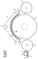
- This invention relates to cards with sliding flats in which fibrous material in thin layer form is worked by a series of surfaces provided with a plurality of points of various shape, inclination and rigidity and driven to move relative to each other, in which the fibrous material is opened into single fibre form, the small trash particles being eliminated together with waste and tangles, the fibres undergoing mutual mixing to form a sliver of untwisted fibres to be fed to the subsequent working stages.
- the raw material 1 consisting of staple fibres collected into the form of a web of approximately rectangular cross-section is fed to the machine by a feed roller 2 which presses and controls it against the board 3 to feed a strip 4 to the opening cylinder 5.
- This cylinder is provided with clothing, ie points inclined in its direction of rotation, and is driven at a considerable rotational speed.
- the fibre strip 4 is hence roughly combed and distributed over the opening cylinder into a layer thinner than the original layer 1. During its anticlockwise rotation the fibre layer encounters clothed segments and blades for removing impurities, after which the fibres pass to the subsequent carding drum 6.
- the drum 6 is driven at a rotational speed less than the cylinder 5, but as it has a much larger diameter its peripheral speed is higher.
- the points on the drum 6 are also inclined in the direction of movement, to remove the fibres from the surface of the cylinder 5 along the closest generating lines between 5 and 6.
- moving flats 7 are located above the top of the drum 6.
- flat cards are also provided with fixed flats, however these do not concern the present invention and hence reference will not be made thereto in the present description.
- the moving flats are in the form of bars having a useful length corresponding to the generating line of the carding drum 6 and a few centimetres in width. That part thereof which faces the drum 6 is provided with clothing in the form of points pointing in the direction of movement. Generally the moving flats move slowly in a direction of rotation which is the same as or opposite to the that of the drum. The two clothes cooperate with typical carding action to provide fibre extension, cleaning, retention and depth control within the point clothing. For some processes it may be required to rotate the flats in the opposite direction to the drum 6. It should however be noted that the peripheral drum speed is generally within the range of 15-40 metres per second, whereas the flat speed is of the order of a few millimetres per second.
- the flats 7 By rotating in the same direction as the drum, the flats 7 circulate in the opposite direction to the drum, conveyed by an articulated chain 8 circulating about a series of drive and guide sprockets 9.
- the flats are guided by guides 10 which precisely control the distance between the drum clothing and the flat clothing, this being the main factor in the good outcome of the operation.
- the guides 10 are positioned at the edge of the flat faces of the drum, and on them there slide the end parts, without points, of the flats 7. The extended and cleaned fibres become arranged into a thin layer on the carding drum 6.
- a discharge cylinder 11 also provided with points inclined in the direction of rotation, to enable the fibres carded by the drum 6 to be withdrawn and then discharged from the cylinder 11 by detachment cylinders not shown in the figure.
- the present invention relates in particular to an improved sliding flat for said flat cards and a system for guiding and driving it.
- German patent application DE-A-3814412 describes various connections using lead-ins, clips and locking keys.
- German patent DE-A-3907396 describes a drive and guide system for flats using toothed belts to which the flats are coupled by various form fits without locking the flats with rigid fixing elements such as nuts and bolts.
- the system has however the typical drawbacks of toothed belts for this type of service.
- the object of the invention is to provide an improved flat for said flat cards, and a system for guiding and driving it which uses an articulated chain drive but without the stated drawbacks of this type of drive when used in systems of the known art.
- coupling between the flat and articulated chain is provided only in the direction of movement of the flats and in the direction along the drum generating line, while leaving said elements not coupled together in the direction perpendicular to the chain movement, by means of a form fit between the flats and chain using recesses and projections of mutually consistent shape, without fixed means for retaining them in position.
- Figures 2 to 5 relate to the chain/flat system, whereas Figure 6 relates to the guiding of the flats along the drum.
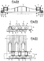
- FIGs 2a, b, c show a flat/chain system according to the invention.
- the flat 7 is preferably of T cross-section to provide sufficient rigidity against flexural stress between the two guide supports 10, which are spaced apart transversely by a distance of the order of one metre or slightly more.
- Their lower face, on the part 12 not involved with the guides 10, carries the card clothing indicated roughly as a series of points in Figures 2 onwards.
- the articulated chain 8 consists essentially of pins 13 and plates 14.
- Those plates 14 which face outwards are provided with an L-bent piece 15 for engaging the flat 7.
- a peg 16 which can be conical or cylindrical, to engage in a likewise conical or cylindrical hole 17 provided in the most outer part of the flat 7.
- This hole can be a through or non-through hole.
- the guiding precision between the chain and flat corresponds to the accuracy of the fit between the hole and peg.
- the flat 7 faithfully follows the guide 10 under the drive of the chain 8, because it is not constrained to the chain radially and is therefore substantially indifferent to its joints.
- FIGS 3a, b, c show an alternative embodiment in which with each pin 13 of the articulated chain 8 there is associated a U-shaped element 20 which carries on its lower part a peg 21 perpendicular to the axis of the pin 13, to engage a hole 22 provided in the most outer part of the flat 7.
- Functions and shapes are analogous to those of Figure 2.
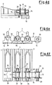
- the form fit is obtained by machining in the two ends of each flat 7 a rounded U-shaped cavity with two projections 30.
- the chains 8 are located external to the flats and carry at each pin 13 of the articulated chain, on that side facing the flats, a peg 31 with its axis parallel to and preferably coincident with the axis of the pin, and intended to fit into their rounded U-shaped cavities formed by the projections 30.
- the fit can be conical or cylindrical, as in the preceding embodiments.
- Figures 4d to 4i show two modifications of the coupling system shown in Figures 4a, b, c.
- the chain coupling element corresponding to the peg 31 of the preceding embodiment, consists of two coupling pegs 33 positioned symmetrically on the two ends of the pin 13.
- the rounded U-shaped cavity corresponding to the cavity formed by the projections 30 of the previous embodiment, consists of two coupling cavities 34 positioned symmetrically at the two ends of each pin 13.
- the chain coupling element corresponding to the peg 31 of the preceding embodiment, consists of the pin 13 itself.
- the rounded U-shaped cavities 35 corresponding to the cavity formed by the projections 30 of the preceding embodiment, are positioned within the gap between the two chain plates 14 at the two ends of each pin 13.
- the form fit is obtained by machining in the two ends of each flat 7 two sharp-edged notches to form prismatic cavities 40.
- a sharp-edged U-shaped profile is shown by way of example.
- the chains 8 carry at the two ends of each pin 13 of the articulated chain a pair of triangular elements 41 the bottom of which carries a sharp-edged projection 42 on the side facing the flats and which is intended to fit into the correspondingly shaped prismatic cavities formed by the sharp-edged notches 40.
- Figures 5d, e, f show a modification of the coupling system shown in Figures 5a, b, c.
- the chain coupling element corresponding to the two projections 42 of the triangular elements 41 of the preceding embodiment, consists of a sharp-edged prismatic element 43 which joins together the two triangles 41 positioned symmetrically at the two ends of each pin 13.
- the sharp-edged cavity 44 for receiving the element 43, and corresponding to the cavity 40 of the preceding embodiment extends towards the ends of the flat 7 and has a shape consistent with that of the prismatic end 43 which it is to receive.
- the embodiments shown in Figures 4 and 5 differ from each other in that the embodiment of Figure 4 enables the peg 31, and the pin 13, to rotate freely within its receiving cavity in the flat about the pin axis, whereas the embodiment of Figure 5 does not allow the prismatic projections to rotate within the prismatic cavities which receive them.
- Figure 6 shows an example of the drive for the flat/chain system according to the invention.
- the series of flats 7 is driven by the articulated chains 8 which follow the path defined by the sprockets 9, of which at least one is motorized and at least one is provided with chain tensioning members.
- the sprockets are in the form of pairs of corresponding sprockets, one for each side of the drum 6.
- the guides 10 are connected to a semicircular portion 50 of L cross-section which prevents the series of flats, connected to the chains 8 while they pass about the sprockets 9B, from separating from them by the effect of gravity and the freedom which they possess in the direction perpendicular to the chain movement.
- An adjustable chain tensioner 51 is shown schematically at the sprocket 9C.
- the guides 10 are connected to another semicircular portion 52 of L cross-section which prevents the series of flats, connected to the chains 8 while they pass about the sprockets 9A, from separating from them by the effect of gravity and the freedom which they possess in the direction perpendicular to the chain movement.
- the material is such that the cylinders and flats require frequent cleaning and clothing replacement.
Landscapes
- Engineering & Computer Science (AREA)
- Textile Engineering (AREA)
- Preliminary Treatment Of Fibers (AREA)
- Organic Low-Molecular-Weight Compounds And Preparation Thereof (AREA)
- Feeding Of Articles By Means Other Than Belts Or Rollers (AREA)
- Braiding, Manufacturing Of Bobbin-Net Or Lace, And Manufacturing Of Nets By Knotting (AREA)
Applications Claiming Priority (2)
| Application Number | Priority Date | Filing Date | Title |
|---|---|---|---|
| ITMI941557 | 1994-07-22 | ||
| ITMI941557A IT1273727B (it) | 1994-07-22 | 1994-07-22 | Cappello strisciante perfezionato per dispositivi di cardatura e sistema per la sua guida e trascinamento |
Publications (2)
| Publication Number | Publication Date |
|---|---|
| EP0693584A1 true EP0693584A1 (de) | 1996-01-24 |
| EP0693584B1 EP0693584B1 (de) | 2000-05-24 |
Family
ID=11369341
Family Applications (1)
| Application Number | Title | Priority Date | Filing Date |
|---|---|---|---|
| EP95201945A Expired - Lifetime EP0693584B1 (de) | 1994-07-22 | 1995-07-14 | Gleitführung und Antrieb für Kardenwanderdeckel |
Country Status (5)
| Country | Link |
|---|---|
| US (1) | US5761770A (de) |
| EP (1) | EP0693584B1 (de) |
| DE (1) | DE69517098T2 (de) |
| ES (1) | ES2148422T3 (de) |
| IT (1) | IT1273727B (de) |
Cited By (2)
| Publication number | Priority date | Publication date | Assignee | Title |
|---|---|---|---|---|
| EP0794271A1 (de) * | 1996-03-04 | 1997-09-10 | F.LLi Marzoli & C. S.p.A. | Deckelkarde mit Zahnriemenantrieb und Oberführung für die Deckel |
| EP0794272A1 (de) * | 1996-03-04 | 1997-09-10 | F.LLi Marzoli & C. S.p.A. | Vorrichtung für Führung und Verbindung des gleitenden Deckels mit dem Antriebsriemen in einer Deckelkarde |
Citations (7)
| Publication number | Priority date | Publication date | Assignee | Title |
|---|---|---|---|---|
| DE48569C (de) * | G. EBENAUER in Elisenfels, Post Seufsen, Bayern | Krempel mit wandernden Deckeln | ||
| DE609287C (de) * | 1933-06-18 | 1935-02-12 | Rieter Joh Jacob & Cie Ag | Vorrichtung zum Einstellen der Laufbogen fuer die Wanderdeckel von Karden |
| FR2403402A1 (fr) * | 1977-09-17 | 1979-04-13 | Truetzschler & Co | Chapelet a chapeaux marchants |
| US4757575A (en) | 1981-05-16 | 1988-07-19 | Carding Specialists (Canada) Ltd. | Carding engine; and to movable flats therefor |
| DE3907396A1 (de) | 1988-09-24 | 1990-03-29 | Truetzschler & Co | Vorrichtung an einer karde mit wanderndem deckel aus mit garnitur versehenen deckelstaeben |
| FR2674262A1 (fr) * | 1991-03-19 | 1992-09-25 | Truetzschler & Co | Dispositif de guidage ameliore pour carde a chapeaux marchants. |
| EP0567747A1 (de) * | 1992-04-30 | 1993-11-03 | Trützschler GmbH & Co. KG | Deckelstab für eine Karde |
Family Cites Families (3)
| Publication number | Priority date | Publication date | Assignee | Title |
|---|---|---|---|---|
| DE3814412A1 (de) * | 1988-04-28 | 1989-11-09 | Truetzschler & Co | Deckelstab fuer karden |
| IT8921641A0 (it) * | 1988-09-24 | 1989-09-06 | Truetzschler & Co | Dispositivo su una carda con cappello mobile fatto di sbarra provviste di guarnizioni. |
| DE59405557D1 (de) * | 1993-06-03 | 1998-05-07 | Rieter Ag Maschf | Wanderdeckelkarde |
-
1994
- 1994-07-22 IT ITMI941557A patent/IT1273727B/it active IP Right Grant
-
1995
- 1995-07-14 DE DE69517098T patent/DE69517098T2/de not_active Expired - Fee Related
- 1995-07-14 EP EP95201945A patent/EP0693584B1/de not_active Expired - Lifetime
- 1995-07-14 ES ES95201945T patent/ES2148422T3/es not_active Expired - Lifetime
- 1995-07-20 US US08/504,475 patent/US5761770A/en not_active Expired - Fee Related
Patent Citations (7)
| Publication number | Priority date | Publication date | Assignee | Title |
|---|---|---|---|---|
| DE48569C (de) * | G. EBENAUER in Elisenfels, Post Seufsen, Bayern | Krempel mit wandernden Deckeln | ||
| DE609287C (de) * | 1933-06-18 | 1935-02-12 | Rieter Joh Jacob & Cie Ag | Vorrichtung zum Einstellen der Laufbogen fuer die Wanderdeckel von Karden |
| FR2403402A1 (fr) * | 1977-09-17 | 1979-04-13 | Truetzschler & Co | Chapelet a chapeaux marchants |
| US4757575A (en) | 1981-05-16 | 1988-07-19 | Carding Specialists (Canada) Ltd. | Carding engine; and to movable flats therefor |
| DE3907396A1 (de) | 1988-09-24 | 1990-03-29 | Truetzschler & Co | Vorrichtung an einer karde mit wanderndem deckel aus mit garnitur versehenen deckelstaeben |
| FR2674262A1 (fr) * | 1991-03-19 | 1992-09-25 | Truetzschler & Co | Dispositif de guidage ameliore pour carde a chapeaux marchants. |
| EP0567747A1 (de) * | 1992-04-30 | 1993-11-03 | Trützschler GmbH & Co. KG | Deckelstab für eine Karde |
Cited By (3)
| Publication number | Priority date | Publication date | Assignee | Title |
|---|---|---|---|---|
| EP0794271A1 (de) * | 1996-03-04 | 1997-09-10 | F.LLi Marzoli & C. S.p.A. | Deckelkarde mit Zahnriemenantrieb und Oberführung für die Deckel |
| EP0794272A1 (de) * | 1996-03-04 | 1997-09-10 | F.LLi Marzoli & C. S.p.A. | Vorrichtung für Führung und Verbindung des gleitenden Deckels mit dem Antriebsriemen in einer Deckelkarde |
| US5749126A (en) * | 1996-03-04 | 1998-05-12 | F.Lli Marzoli & C. S.P.A. | Device for guiding and coupling the sliding flat with the drive belt in a flat card |
Also Published As
| Publication number | Publication date |
|---|---|
| EP0693584B1 (de) | 2000-05-24 |
| US5761770A (en) | 1998-06-09 |
| ES2148422T3 (es) | 2000-10-16 |
| ITMI941557A0 (it) | 1994-07-22 |
| ITMI941557A1 (it) | 1996-01-22 |
| IT1273727B (it) | 1997-07-09 |
| DE69517098T2 (de) | 2000-11-02 |
| DE69517098D1 (de) | 2000-06-29 |
Similar Documents
| Publication | Publication Date | Title |
|---|---|---|
| EP0794272B1 (de) | Vorrichtung für Führung und Verbindung des gleitenden Deckels mit dem Antriebsriemen in einer Deckelkarde | |
| EP1446350A1 (de) | Aufzugssystem | |
| US5054167A (en) | Combing needle for spinning machines | |
| EP0693584A1 (de) | Gleitführung und Antrieb für Kardenwanderdeckel | |
| US4955111A (en) | Travelling flats assembly for a carding machine | |
| EP0794271B1 (de) | Deckelkarde mit Zahnriemenantrieb und Oberführung für die Deckel | |
| US3995351A (en) | Flat section in carding machine | |
| CN87104662A (zh) | 梳理装置 | |
| US7062819B2 (en) | System for guiding and drawing along mobile flats in a flat card | |
| CN110002204B (zh) | 输送桥以及具有巷道输送机和输送桥的输送设备 | |
| WO2003087446A2 (en) | Carding element with saw-teeth | |
| DE684139C (de) | Trockenanlage fuer Bahnen aus Papier, Cellulose, Gewebe oder aehnlichen Stoffen | |
| EP3321400B1 (de) | Offenend-spinnmaschine mit einer schmutzentsorgungseinrichtung | |
| US6058582A (en) | Napper machine | |
| CN1327055C (zh) | 用于清理盖板梳棉机中的移动盖板导向件的装置 | |
| CN101239524A (zh) | 用于将承印物幅面拉入印刷机中的拉入装置 | |
| GB2323099A (en) | Making pinned devices for fibre treatment | |
| GB2121842A (en) | Needle bar drawing device | |
| US5237725A (en) | Method and apparatus for opening fiber bales | |
| US1732860A (en) | Card-cleaning device | |
| SU1454883A1 (ru) | Рабоча камера пильного джина | |
| SU1353846A1 (ru) | Устройство дл регенерации отходов волокнистого материала | |
| US1059726A (en) | Combing-machine. | |
| EP0936293A3 (de) | Schmutzentsorgungseinrichtung für eine Offenend-Spinnmaschine | |
| JP2024053758A (ja) | 除塵機 |
Legal Events
| Date | Code | Title | Description |
|---|---|---|---|
| PUAI | Public reference made under article 153(3) epc to a published international application that has entered the european phase |
Free format text: ORIGINAL CODE: 0009012 |
|
| AK | Designated contracting states |
Kind code of ref document: A1 Designated state(s): CH DE ES FR GB IT LI |
|
| 17P | Request for examination filed |
Effective date: 19960705 |
|
| 17Q | First examination report despatched |
Effective date: 19980907 |
|
| GRAG | Despatch of communication of intention to grant |
Free format text: ORIGINAL CODE: EPIDOS AGRA |
|
| GRAG | Despatch of communication of intention to grant |
Free format text: ORIGINAL CODE: EPIDOS AGRA |
|
| GRAH | Despatch of communication of intention to grant a patent |
Free format text: ORIGINAL CODE: EPIDOS IGRA |
|
| GRAH | Despatch of communication of intention to grant a patent |
Free format text: ORIGINAL CODE: EPIDOS IGRA |
|
| RAP1 | Party data changed (applicant data changed or rights of an application transferred) |
Owner name: MARZOLI S.P.A. |
|
| GRAA | (expected) grant |
Free format text: ORIGINAL CODE: 0009210 |
|
| ITF | It: translation for a ep patent filed | ||
| AK | Designated contracting states |
Kind code of ref document: B1 Designated state(s): CH DE ES FR GB IT LI |
|
| REG | Reference to a national code |
Ref country code: CH Ref legal event code: EP |
|
| REF | Corresponds to: |
Ref document number: 69517098 Country of ref document: DE Date of ref document: 20000629 |
|
| REG | Reference to a national code |
Ref country code: CH Ref legal event code: NV Representative=s name: AMMANN PATENTANWAELTE AG BERN |
|
| ET | Fr: translation filed | ||
| REG | Reference to a national code |
Ref country code: ES Ref legal event code: FG2A Ref document number: 2148422 Country of ref document: ES Kind code of ref document: T3 |
|
| PLBE | No opposition filed within time limit |
Free format text: ORIGINAL CODE: 0009261 |
|
| STAA | Information on the status of an ep patent application or granted ep patent |
Free format text: STATUS: NO OPPOSITION FILED WITHIN TIME LIMIT |
|
| 26N | No opposition filed | ||
| REG | Reference to a national code |
Ref country code: GB Ref legal event code: IF02 |
|
| PGFP | Annual fee paid to national office [announced via postgrant information from national office to epo] |
Ref country code: FR Payment date: 20040708 Year of fee payment: 10 |
|
| PGFP | Annual fee paid to national office [announced via postgrant information from national office to epo] |
Ref country code: GB Payment date: 20040714 Year of fee payment: 10 |
|
| PGFP | Annual fee paid to national office [announced via postgrant information from national office to epo] |
Ref country code: DE Payment date: 20050707 Year of fee payment: 11 |
|
| PGFP | Annual fee paid to national office [announced via postgrant information from national office to epo] |
Ref country code: CH Payment date: 20050713 Year of fee payment: 11 |
|
| PG25 | Lapsed in a contracting state [announced via postgrant information from national office to epo] |
Ref country code: GB Free format text: LAPSE BECAUSE OF NON-PAYMENT OF DUE FEES Effective date: 20050714 |
|
| PGFP | Annual fee paid to national office [announced via postgrant information from national office to epo] |
Ref country code: ES Payment date: 20050818 Year of fee payment: 11 |
|
| GBPC | Gb: european patent ceased through non-payment of renewal fee |
Effective date: 20050714 |
|
| PG25 | Lapsed in a contracting state [announced via postgrant information from national office to epo] |
Ref country code: FR Free format text: LAPSE BECAUSE OF NON-PAYMENT OF DUE FEES Effective date: 20060331 |
|
| REG | Reference to a national code |
Ref country code: FR Ref legal event code: ST Effective date: 20060331 |
|
| PG25 | Lapsed in a contracting state [announced via postgrant information from national office to epo] |
Ref country code: LI Free format text: LAPSE BECAUSE OF NON-PAYMENT OF DUE FEES Effective date: 20060731 Ref country code: CH Free format text: LAPSE BECAUSE OF NON-PAYMENT OF DUE FEES Effective date: 20060731 |
|
| PG25 | Lapsed in a contracting state [announced via postgrant information from national office to epo] |
Ref country code: DE Free format text: LAPSE BECAUSE OF NON-PAYMENT OF DUE FEES Effective date: 20070201 |
|
| REG | Reference to a national code |
Ref country code: CH Ref legal event code: PL |
|
| REG | Reference to a national code |
Ref country code: ES Ref legal event code: FD2A Effective date: 20060715 |
|
| PG25 | Lapsed in a contracting state [announced via postgrant information from national office to epo] |
Ref country code: ES Free format text: LAPSE BECAUSE OF NON-PAYMENT OF DUE FEES Effective date: 20060715 |
|
| PGFP | Annual fee paid to national office [announced via postgrant information from national office to epo] |
Ref country code: IT Payment date: 20130719 Year of fee payment: 19 |
|
| PG25 | Lapsed in a contracting state [announced via postgrant information from national office to epo] |
Ref country code: IT Free format text: LAPSE BECAUSE OF NON-PAYMENT OF DUE FEES Effective date: 20140714 |