EP0693455B1 - Auf flachen biegsamen Gurten wirkende Zug- oder Hebevorrichtung mit Backen - Google Patents
Auf flachen biegsamen Gurten wirkende Zug- oder Hebevorrichtung mit Backen Download PDFInfo
- Publication number
- EP0693455B1 EP0693455B1 EP95630085A EP95630085A EP0693455B1 EP 0693455 B1 EP0693455 B1 EP 0693455B1 EP 95630085 A EP95630085 A EP 95630085A EP 95630085 A EP95630085 A EP 95630085A EP 0693455 B1 EP0693455 B1 EP 0693455B1
- Authority
- EP
- European Patent Office
- Prior art keywords
- jaws
- strap
- pairs
- guide
- jaw
- Prior art date
- Legal status (The legal status is an assumption and is not a legal conclusion. Google has not performed a legal analysis and makes no representation as to the accuracy of the status listed.)
- Expired - Lifetime
Links
Images


Classifications
-
- B—PERFORMING OPERATIONS; TRANSPORTING
- B66—HOISTING; LIFTING; HAULING
- B66D—CAPSTANS; WINCHES; TACKLES, e.g. PULLEY BLOCKS; HOISTS
- B66D3/00—Portable or mobile lifting or hauling appliances
- B66D3/02—Manually-operated, e.g. lever-actuated, devices operating on ropes, cables, or chains for hauling in a mainly horizontal direction
Definitions
- the invention relates to a traction device or lifting of a link connected to a load, operating by two pairs of jaws, reciprocating, in particular according to the principle of self-tightening by the load and, in particular also, provided with a pre-tightening device off load and simultaneous declutching of the two pairs of jaws.
- French patent application No. 2,252,280 relates to a device for exerting traction on cables or ropes with a certain stiffness, such as those commonly used in pleasure cruising.
- the traction device has two cable or rope guide tubes, one engaged in the other and each carried by a plate also carrying a two-jaw cleat.
- the patent application German no. 37 31 383 relates to a traction device with flexible cable or strip provided with an envelope to guide the flexible cable or strip between the pairs of jaws.
- the object of the present invention is to apply a mechanical assembly with the same kinematic design as indicated above, when operating a flat strap and flexible used as a link for moving a charge.
- the traction and lifting device is characterized in that that said pairs of jaws having surfaces of flat tightening corresponding to the wide sides of a strap flexible flat profile are supplemented by two guides arranged respectively along each of the two faces wide of the strap and in its longitudinal direction, so as to prevent it from bending or loop between the two pairs of jaws when these approach each other, and in that each of the two jaws of a first pair of the two pairs of jaws is provided with a fitted cavity longitudinally in these jaws, and one of the two guides is attached to one of the jaws of the other pair of two pairs of jaws and the other guide is attached to the other jaw of the other pair of the two pairs of jaws, the guide located on one side of the strap being received sliding in the cavity of the jaw, located on the same side of the strap, from the first pair of the two pairs of jaws while the other guide is received sliding in the cavity of the other jaw the first pair of jaws.
- the strap can fold in its part between the two pairs of jaws, when these approach one of the other.
- the two guides are constantly in contact, or almost in contact with the strap to prevent everything disorder in its movement, and do not stand between the inner faces of the jaws and the strap. They are positioned on the longitudinal path of the jaws without hinder the translational movement of these and without their tightening movement only applies pressure from guides on the strap.
- At least two of the four jaws not located on the same side of the strap, slide on the guide located their side with respect to the strap, by means of cavities longitudinal arranged in these jaws and of section corresponding to that of said guide, while the other end of each guide will be attached to the jaw of the other pair.
- the traction and lifting device is characterized by what said pairs of jaws having surfaces of flat tightening corresponding to the wide sides of a strap flexible flat profile are supplemented by two guides arranged respectively along each of the two faces wide of the strap and in its longitudinal direction, so as to prevent it from bending or loop between the two pairs of jaws when these approach each other, and in that the guides are attached to either one or both ends of the device housing, and the jaws, located on one sides of the strap, two pairs of jaws are sliding mounted on the guide located on the same side of the strap, while in the other jaws of the two pairs of jaws are slidably mounted on each other guide.
- the longitudinal cavity of the jaws may be closed laterally inside the jaw, or be open laterally on the internal face of the jaw or a clamping plate thereof.
- the section of the cavity may have an appropriate shape such as a tail dovetail, in cooperation with a corresponding shape of the guide section, preventing the guide from escaping laterally from its housing.
- the guide rods serve as guide for both the strap and the jaws.
- the sides of the jaws with the surfaces clamps can be flat, but in order to wedge laterally the strap in each pair of jaws, one of the jaws or both jaws of each pair may have two side flanks bordering clamping surfaces. According to another mode of realization of one of the jaws with or without raised side is positioned inside its opposing jaw with lateral raised, so as to form with it a frame for the strap.
- the inner side of the jaws or of their clamping plates may include footprints or reliefs to improve cooperation between jaws and strap.
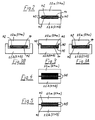
- FIG 1 the housing 10 of an apparatus traction or lifting is shown schematically.
- This housing has an inlet passage 12 through which the strap 14 enters inside the housing 10.
- the strap comes out of the device housing by an outlet (not shown) provided at the opposite end of the housing 10.
- the device is equipped with a walking lever forward 16 and a reverse lever 18 as well as a clutch release handle 20.
- a walking lever forward 16 and a reverse lever 18 as well as a clutch release handle 20.
- the forward lever 16 is mounted for pivoting around an axis 26 fixed relative to the casing 10.
- the forward lever 16 is connected by a connecting rod 28 to the jaw block before 22 and by a connecting rod 30 to the block rear jaw.
- the reverse lever 18 is pivotally connected to the front jaw block 22 and a connecting rod 32 is pivotally connected to the lever reverse 18 and rear jaw block 24.
- the release handle 20 is connected by a link 34 to the reverse lever 18.
- jaws 22a and 22b move away from the strap and the block front jaw 22 and moved backwards causing the two jaw blocks move closer together.
- the forward lever 16 is again pivoted to the right side clockwise around the axis 26 the movement of the jaws 22 and 24 is reversed, i.e. the jaws move away one from the other.
- the jaw block before 22 clamps now the strap to advance it to the left side while the rear jaw block 24 moves on the strap freely backwards.
- the jaws have a section simple rectangular cross.
- the jaws 22a, 22b, 24a, and 24b of each pair of jaws each have a U-shaped cross section with a 40 on each side of the clamping surface 42, the two forms in a U, in each grip of jaws, facing each other.
- a section housing flattened rectangular is made to receive the strap in the inner faces of the jaws. This housing allows the strap to be guided laterally between the jaws of the same pair.
- one 22b, 24b only of the jaws of a same pair is U-shaped, the other jaw 22a, 24a, of simple rectangular section being dimensioned for ability to lodge between branches of jaw U-shaped antagonist.
- one of the jaws 22b, 24b having a U shape the other jaw 22a, 24a of the same pair has a T shape obtained by lateral shoulders, the central part of the T fitting into the housing of the opposing U-shaped jaw.
- the two jaws 22a, 24a, 22b, 24b of the same pair are U-shaped and are face as in the embodiment of the figure 2 with the difference that one of the two jaws is wider than the other, so the latter can be accommodated in the tightening movement.
- the branches or jaw shoulders are sized in the tightening direction of the strap so that two opposing jaws never come to a stop against each other when the clamping movement of the strap 14 is brought to its maximum limit.
- FIG. 4 and 5 correspond to the embodiment of FIG. 2 except that according to the mode of execution of figure 4 of clamping pads of suitable materials 46 are provided between the opposing jaws 22a, 22b and 24a, 24b and strap 14 to ensure optimum grip between the jaws and the strap.
- the clamping surfaces 42 of the jaws 22a, 22b and 24a, 24b have imprints and / or reliefs 48 configured to optimize the cooperation of the jaws and strap.
- plates or footprints and / or reliefs can also be provided in the embodiment of Figures 3, 3A and 3B. Platelets may also have fingerprints and / or reliefs to allow optimal tightening of the strap.
- FIG. 6 represents a first mode of realization of a strap guide fixed on the jaw block upstream 24.
- This strap guide 50 comprises two pieces of guide 52 and 54.
- Each guide piece 52 and 54 has a head part attached by screws 56 to one of the jaws 22a, 22b of the rear jaw block 24 and includes a guide arm 50a, 50b extending axially and received in one of the jaws 22a, 22b of the front jaw block 22.
- the guide arms 50a, 50b of the strap guide 50 are slidably received in corresponding cavities 51a, 51b formed in the jaws 22a, 22b of the front jaw block 22 and are arranged respectively along each of the two wide sides of the strap 14 in its direction longitudinal so as to prohibit it from folding or looping movement between the two blocks jaws 22 and 24 when these approach one the other.
- This embodiment is also shown in Figure 1, see guide arms 50a, 50b of the rear jaws 24a, 24b, received in the passages made in the jaws before 22a and 22b.
- the upper jaws 22a, 24b slide on a fixed strap guide or runner 60 located on the upper side strap 14 while the jaws 22b, 24b slide on a strap guide or fixed slide similar 62 located on the lower side of the strap 14.
- the two slides 60 and 62 are fixed either to one either at the two ends of the casing 10 of the lifting or pulling.
- Backstage 60 and 62 are provided for the same purpose as the guide parts 52, 54 of the embodiment of FIG. 6, that is to say they serve to prevent strap 14 from moving fold or loop between the two jaw blocks 22 and 24 when these blocks approach each other.
- FIGS. 8A, 8B and 8C are views in cross section, along line 8-8 of figure 6, jaws 22a, 22b of the front jaw block 22. Tel that represented in FIG. 8A the cavities of sliding 51a, 51b for the guide arms 50a, 50b are laterally closed inside the jaws 22a, 22b and have a section corresponding to that of guide arm 50a, 50b.
- the cavities sliding 51a, 51b made in the jaws 22a, 22b for the guide arms 50a, 50b are formed by notches longitudinally open on the clamping surface 42 of the jaws 22a and 22b while according to figure 8B the section of the notch longitudinally open for sliding the jaws 22a, 22b on the guide arms 50a, 50b in cooperation with the guide arm section has a dovetail shape preventing the guide arm from escape from this gash.
- the cavities 60a, 62a formed in the jaws 22a, 22b and 24a, 24b of the embodiment of the Figure 7 for sliding mounting on the slides 60 and 62 can also be formed such that shown in Figures 8A, 8B and 8C.
Landscapes
- Engineering & Computer Science (AREA)
- Mechanical Engineering (AREA)
- Basic Packing Technique (AREA)
- Clamps And Clips (AREA)
- Folding Of Thin Sheet-Like Materials, Special Discharging Devices, And Others (AREA)
- Load-Engaging Elements For Cranes (AREA)
- Buckles (AREA)
Claims (9)
- Vorrichtung zum Ziehen oder Heben eines an eine Last angeschlossenen Zugmittels, mit zwei Klemmbackenpaaren (22a, 22b; 24a, 24b), die hin und her beweglich sind, insbesondere entsprechend dem Prinzip des automatischen Klemmens durch die Last, und insbesondere auch mit einer Einrichtung (20) zum Vorklemmen bei Lastabwesenheit und zum gleichzeitigen Öffnen der zwei Klemmbackenpaare (22a, 22b; 24a, 24b), dadurch gekennzeichnet, daß die Klemmbackenpaare (22a, 22b; 24a, 24b) versehen mit flachen Klemmflächen (42) entsprechend den breiten Flächen eines flexiblen Gurtes (14) mit flachem Querschnitt vervollständigt sind durch zwei Führungen (50a, 50b), welche sich jeweils längs einer jeden der zwei breiten Flächen des Gurtes (14) befinden und sich in Längsrichtung desselben erstrecken, um eine Falt- oder Schleifenbildung zwischen den zwei Klemmbackenpaaren (22a, 22b; 24a, 24b) zu verhindern, wenn diese sich aufeinander zu bewegen, und daß jede der zwei Klemmbacken (22a, 22b) eines ersten Paares der zwei Klemmbackenpaare mit einem Hohlraum (51a, 51b) in Längsrichtung in diesen Klemmbacken (22a, 22b) versehen ist, und eine (50a) der beiden Führungen (50a, 50b) an einer der Klemmbacken (24a) des anderen Paares der zwei Klemmbackenpaare und die andere Führung (50b) an der anderen Klemmbacke (24b) des anderen Paares der zwei Klemmbackenpaare befestigt ist, wobei die auf einer Seite des Gurtes liegende Führung gleitend aufgenommen ist in dem Hohlraum der Klemmbacke (22a), welche sich auf der gleichen Seite des Gurtes befindet, des ersten Paares der zwei Klemmbackenpaare, während die Führung (50b) gleitend aufgenommen ist in dem Hohlraum der anderen Klemmbacke (22b) des ersten Klemmbackenpaares (22a, 22b).
- Vorrichtung zum Ziehen oder Heben eines an eine Last angeschlossenen Zugmittels, mit zwei Klemmbackenpaaren (22a, 22b; 24a, 24b), die hin und her beweglich sind, insbesondere entsprechend dem Prinzip des automatischen Klemmens durch die Last, und insbesondere auch mit einer Einrichtung (20) zum Vorklemmen bei Lastabwesenheit und zum gleichzeitigen Öffnen der zwei Klemmbackenpaare (22a, 22b; 24a, 24b), dadurch gekennzeichnet, daß die Klemmbackenpaare (22a, 22b; 24a, 24b) versehen mit flachen Klemmflächen (42) entsprechend den breiten Flächen eines flexiblen Gurtes (14) mit flachem Querschnitt vervollständigt sind durch zwei Führungen (60, 62), welche sich jeweils längs einer jeden der zwei breiten Flächen des Gurtes (14) befinden und sich in Längsrichtung desselben erstrecken, um eine Falt- oder Schleifenbildung zwischen den zwei Klemmbackenpaaren (22a, 22b; 24a, 24b) zu verhindern, wenn diese sich aufeinander zu bewegen, und daß die Führungen (60, 62) an einem oder beiden Enden des Gehäuses (10) der Vorrichtung befestigt sind, und die sich auf einer Seite des Gurtes befindenden Klemmbacken (22a, 24a) der zwei Klemmbackenpaare verschiebbar auf der Führung (60) angeordnet sind, die sich auf der gleichen Seite des Gurtes befindet, während die anderen Klemmbacken (22b, 24b) der zwei Klemmbackenpaare verschiebbar auf der anderen Führung (62) angeordnet sind, wobei die Führungen (60, 62) durch Gleithohlräume (60a, 62a) in den Klemmbacken (22a, 22b; 24a, 24b) ragen.
- Vorrichtung nach Anspruch 1 oder 2, dadurch gekennzeichnet, daß eine der Klemmbacken oder die beiden Klemmbacken eines jeden Klemmbackenpaares (22a, 22b; 24a, 24b) seitliche Erhebungen (40) aufweisen, welche die Klemmflächen (42) säumen.
- Vorrichtung nach einem der Ansprüche 1 bis 3, dadurch gekennzeichnet, daß eine der Klemmbacken (22a, 24a) in der gegenüberliegenden Klemmbacke (22b; 24b) aufgenommen ist, welche seitliche Erhebungen (40) aufweist, um zusammen mit dieser eine Einrahmung für das Hindurchgleiten oder Klemmen des Gurtes (14) zu bilden, der sich darin befindet.
- Vorrichtung nach einem der Ansprüche 1 bis 4, dadurch gekennzeichnet, daß Plättchen (46) aus einem geeigneten Werkstoff für eine optimale Haftung zwischen der Klemmbacke und dem Gurt auf der Innenfläche der Klemmbacken (22a, 22b; 24a, 24b) befestigt sind.
- Vorrichtung nach einem der Ansprüche 1 bis 5, dadurch gekennzeichnet, daß die Klemmflächen (42) der Klemmbacken (22a, 22b; 24a, 24b) oder ihre Plättchen (46) Vertiefungen und/oder Erhebungen (48) aufweisen, die geformt sind, um die Zusammenwirkung der Klemmbacken (22a, 22b; 24a, 24b) und des Gurtes (14) zu optimieren.
- Vorrichtung nach einem der Ansprüche 1 bis 6, dadurch gekennzeichnet, daß der Gleithohlraum (51a, 51b; 60a, 62a) der Klemmbacken (22a, 22b; 24a, 24b) seitlich innerhalb der Klemmbacken verschlossen ist, gemäß einer Form, welche der Form der Führung (50a, 50b; 60, 62) entspricht.
- Vorrichtung nach einem der Ansprüche 1 bis 6, dadurch gekennzeichnet, daß der Gleithohlraum (51a, 51b; 60a, 62a) der Klemmbacken (22a, 22b; 24a, 24b) eine Nut ist, welche in Längsrichtung offen ist auf der Innenfläche dieser Klemmbacken (22a, 22b; 24a, 24b).
- Vorrichtung nach Anspruch 8, dadurch gekennzeichnet, daß der Querschnitt der Nut, in Zusammenwirkung mit dem Querschnitt der Führung (50a, 50b; 60, 62) eine Form aufweist, die ein Austritt der Führung (50a, 50b; 60, 62) aus dieser Nut verhindert.
Applications Claiming Priority (2)
| Application Number | Priority Date | Filing Date | Title |
|---|---|---|---|
| FR9408860 | 1994-07-18 | ||
| FR9408860A FR2722489B1 (fr) | 1994-07-18 | 1994-07-18 | Appareil de levage ou de traction a machoires, agissant sur des sangles souples a profil plat |
Publications (2)
| Publication Number | Publication Date |
|---|---|
| EP0693455A1 EP0693455A1 (de) | 1996-01-24 |
| EP0693455B1 true EP0693455B1 (de) | 1999-12-29 |
Family
ID=9465481
Family Applications (1)
| Application Number | Title | Priority Date | Filing Date |
|---|---|---|---|
| EP95630085A Expired - Lifetime EP0693455B1 (de) | 1994-07-18 | 1995-07-18 | Auf flachen biegsamen Gurten wirkende Zug- oder Hebevorrichtung mit Backen |
Country Status (6)
| Country | Link |
|---|---|
| US (1) | US5655754A (de) |
| EP (1) | EP0693455B1 (de) |
| CN (1) | CN1121480A (de) |
| DE (1) | DE69514161T2 (de) |
| ES (1) | ES2141319T3 (de) |
| FR (1) | FR2722489B1 (de) |
Families Citing this family (5)
| Publication number | Priority date | Publication date | Assignee | Title |
|---|---|---|---|---|
| US6488267B1 (en) * | 2000-09-12 | 2002-12-03 | The United States Of America As Represented By The Secretary Of The Army | Apparatus for lifting or pulling a load |
| US8020835B2 (en) * | 2007-11-02 | 2011-09-20 | Lockheed Martin Corporation | Device for installing and removing high insertion force modules |
| CN102439808B (zh) * | 2009-06-30 | 2016-01-20 | 株式会社永木精机 | 卡线器 |
| CN106882708B (zh) * | 2017-02-13 | 2018-02-16 | 太原理工大学 | 一种垂直提升装置及方法 |
| CN107618808A (zh) * | 2017-10-31 | 2018-01-23 | 山西新格机电科技有限公司 | 一种全自动液压输送带夹紧牵引设备 |
Family Cites Families (13)
| Publication number | Priority date | Publication date | Assignee | Title |
|---|---|---|---|---|
| FR914400A (fr) | 1945-09-05 | 1946-10-07 | Appareil de traction et de levage à câble métallique | |
| US2990091A (en) * | 1953-01-13 | 1961-06-27 | Glastrusions | Apparatus for feeding plastic bars, tubes and like elongated stock |
| FR1342298A (fr) * | 1962-09-27 | 1963-11-08 | Pinces auto-serreuses pour appareil de traction et de levage ainsi que les appareils de traction et de levage pourvus desdites pinces auto-serreuses ou similaires | |
| FR1513335A (fr) * | 1966-10-25 | 1968-02-16 | Tractel S A Soc | Dispositif de pré-serrage des mâchoires de pinces agissant sur un câble avec effet d'auto-serrage |
| BE792753A (fr) * | 1971-12-15 | 1973-03-30 | Milbras S P R L | Perfectionnements aux pinces a auto-serrage pour un treuil a cable libre |
| FR2290385A2 (fr) * | 1973-11-23 | 1976-06-04 | Doucin Michel | Dispositif de traction pour cables et filins |
| FR2252280A1 (en) * | 1973-11-23 | 1975-06-20 | Doucin Michel | Rope and cable winch - has two gripping blocks alternately gripping rope and alternately sliding towards and away from each other |
| DE2928028A1 (de) * | 1979-07-11 | 1981-01-29 | Rutzki Geb Wilke Edith | Spannschloss fuer gurtbaender |
| EP0064571B1 (de) * | 1981-05-13 | 1985-01-23 | Secalt S.A. | Vorrichtung zum Einklemmen und/oder Längsbewegen eines langgestreckten Zugmittels |
| FR2524454A1 (fr) * | 1982-04-01 | 1983-10-07 | Tractel Sa | Appareil de traction pour le halage d'un cable, d'une barre ou d'un organe comparable |
| US4483517A (en) * | 1982-04-01 | 1984-11-20 | Secalt S.A. | Tractive apparatus for hauling a cable, a bar or a similar member |
| DD233744A3 (de) * | 1984-01-24 | 1986-03-12 | Bauakademie Ddr | Hydraulische seilzugvorrichtung |
| DE3731383A1 (de) * | 1987-09-18 | 1989-04-06 | Kreiss Burkhard | Seilzuggeraet |
-
1994
- 1994-07-18 FR FR9408860A patent/FR2722489B1/fr not_active Expired - Fee Related
-
1995
- 1995-07-13 US US08/502,096 patent/US5655754A/en not_active Expired - Fee Related
- 1995-07-18 ES ES95630085T patent/ES2141319T3/es not_active Expired - Lifetime
- 1995-07-18 DE DE69514161T patent/DE69514161T2/de not_active Expired - Fee Related
- 1995-07-18 EP EP95630085A patent/EP0693455B1/de not_active Expired - Lifetime
- 1995-07-18 CN CN95108437A patent/CN1121480A/zh active Pending
Also Published As
| Publication number | Publication date |
|---|---|
| US5655754A (en) | 1997-08-12 |
| DE69514161T2 (de) | 2000-08-24 |
| FR2722489A1 (fr) | 1996-01-19 |
| ES2141319T3 (es) | 2000-03-16 |
| DE69514161D1 (de) | 2000-02-03 |
| EP0693455A1 (de) | 1996-01-24 |
| CN1121480A (zh) | 1996-05-01 |
| FR2722489B1 (fr) | 1996-08-30 |
Similar Documents
| Publication | Publication Date | Title |
|---|---|---|
| FR2658108A1 (fr) | Dispositif de serrage a action rapide. | |
| EP0448484A1 (de) | Schutzabdeckung für einen linearen Führungsmodul zum Verschieben und Handhaben von Teilen und Zubehör | |
| FR2635289A1 (fr) | Etau a action rapide | |
| FR2658107A1 (fr) | Outil a main de serrage. | |
| EP0058375B1 (de) | Presszange | |
| FR2585610A1 (fr) | Pince de traction et de coupe pour laniere, en particulier pour collier de serrage | |
| EP0693455B1 (de) | Auf flachen biegsamen Gurten wirkende Zug- oder Hebevorrichtung mit Backen | |
| EP0958896A1 (de) | Mehrzwecktaschenwerkzeug mit einer Zange | |
| EP0074371B1 (de) | Verbesserungen an zangen | |
| EP0401099B1 (de) | Gerät für den Antrieb eines Lastenträgerbandes mit einer kombinierten Vorrichtung zur Ablenkung der Last und Führung des Bandes | |
| FR2945229A1 (fr) | Outils de prehension actionnes manuellement | |
| FR2672881A1 (fr) | Pince pour le levage d'elements plats, tels que des paquets de toles. | |
| FR2611650A1 (fr) | Dispositif de nouage d'un lien souple | |
| EP0136189B1 (de) | Vorrichtung zum Greifen von Behältern, insbesondere Lagerkassetten | |
| FR2500344A1 (fr) | Perfectionnements apportes aux cisailles hydrauliques | |
| EP0092455A1 (de) | Zugvorrichtung zum Einholen eines Seils, eines Stabs oder eines vergleichbaren Elements | |
| FR2524454A1 (fr) | Appareil de traction pour le halage d'un cable, d'une barre ou d'un organe comparable | |
| EP1375046B1 (de) | Tragbare Punktschweisszange | |
| EP1280632B1 (de) | Zange mit kraftverstärkung | |
| FR2640605A1 (fr) | Pince mecanique autoserrante | |
| FR2585608A1 (fr) | Dispositif de prehension | |
| FR2669861A1 (fr) | Dispositif d'actionnement pour un toit pare-soleil de vehicule automobile. | |
| FR2671689A1 (fr) | Elagueur. | |
| EP4252976A1 (de) | Parallelgreifer mit referenzierung eines zwei spannbackens | |
| BE334551A (de) |
Legal Events
| Date | Code | Title | Description |
|---|---|---|---|
| PUAI | Public reference made under article 153(3) epc to a published international application that has entered the european phase |
Free format text: ORIGINAL CODE: 0009012 |
|
| AK | Designated contracting states |
Kind code of ref document: A1 Designated state(s): CH DE ES GB LI |
|
| 17P | Request for examination filed |
Effective date: 19960530 |
|
| 17Q | First examination report despatched |
Effective date: 19980827 |
|
| GRAG | Despatch of communication of intention to grant |
Free format text: ORIGINAL CODE: EPIDOS AGRA |
|
| GRAG | Despatch of communication of intention to grant |
Free format text: ORIGINAL CODE: EPIDOS AGRA |
|
| GRAG | Despatch of communication of intention to grant |
Free format text: ORIGINAL CODE: EPIDOS AGRA |
|
| GRAH | Despatch of communication of intention to grant a patent |
Free format text: ORIGINAL CODE: EPIDOS IGRA |
|
| GRAH | Despatch of communication of intention to grant a patent |
Free format text: ORIGINAL CODE: EPIDOS IGRA |
|
| GRAA | (expected) grant |
Free format text: ORIGINAL CODE: 0009210 |
|
| AK | Designated contracting states |
Kind code of ref document: B1 Designated state(s): CH DE ES GB LI |
|
| REG | Reference to a national code |
Ref country code: CH Ref legal event code: EP |
|
| REF | Corresponds to: |
Ref document number: 69514161 Country of ref document: DE Date of ref document: 20000203 |
|
| REG | Reference to a national code |
Ref country code: ES Ref legal event code: FG2A Ref document number: 2141319 Country of ref document: ES Kind code of ref document: T3 |
|
| GBT | Gb: translation of ep patent filed (gb section 77(6)(a)/1977) |
Effective date: 20000317 |
|
| PLBE | No opposition filed within time limit |
Free format text: ORIGINAL CODE: 0009261 |
|
| STAA | Information on the status of an ep patent application or granted ep patent |
Free format text: STATUS: NO OPPOSITION FILED WITHIN TIME LIMIT |
|
| 26N | No opposition filed | ||
| REG | Reference to a national code |
Ref country code: GB Ref legal event code: IF02 |
|
| PGFP | Annual fee paid to national office [announced via postgrant information from national office to epo] |
Ref country code: GB Payment date: 20030716 Year of fee payment: 9 |
|
| PGFP | Annual fee paid to national office [announced via postgrant information from national office to epo] |
Ref country code: DE Payment date: 20040713 Year of fee payment: 10 |
|
| PG25 | Lapsed in a contracting state [announced via postgrant information from national office to epo] |
Ref country code: GB Free format text: LAPSE BECAUSE OF NON-PAYMENT OF DUE FEES Effective date: 20040718 |
|
| GBPC | Gb: european patent ceased through non-payment of renewal fee |
Effective date: 20040718 |
|
| PG25 | Lapsed in a contracting state [announced via postgrant information from national office to epo] |
Ref country code: DE Free format text: LAPSE BECAUSE OF NON-PAYMENT OF DUE FEES Effective date: 20060201 |
|
| PGFP | Annual fee paid to national office [announced via postgrant information from national office to epo] |
Ref country code: ES Payment date: 20070727 Year of fee payment: 13 |
|
| PGFP | Annual fee paid to national office [announced via postgrant information from national office to epo] |
Ref country code: CH Payment date: 20070713 Year of fee payment: 13 |
|
| REG | Reference to a national code |
Ref country code: CH Ref legal event code: PL |
|
| PG25 | Lapsed in a contracting state [announced via postgrant information from national office to epo] |
Ref country code: LI Free format text: LAPSE BECAUSE OF NON-PAYMENT OF DUE FEES Effective date: 20080731 Ref country code: CH Free format text: LAPSE BECAUSE OF NON-PAYMENT OF DUE FEES Effective date: 20080731 |
|
| REG | Reference to a national code |
Ref country code: ES Ref legal event code: FD2A Effective date: 20080719 |
|
| PG25 | Lapsed in a contracting state [announced via postgrant information from national office to epo] |
Ref country code: ES Free format text: LAPSE BECAUSE OF NON-PAYMENT OF DUE FEES Effective date: 20080719 |