EP0693455B1 - Traction or lifting device with jaws, acting on low profile flexible straps - Google Patents
Traction or lifting device with jaws, acting on low profile flexible straps Download PDFInfo
- Publication number
- EP0693455B1 EP0693455B1 EP95630085A EP95630085A EP0693455B1 EP 0693455 B1 EP0693455 B1 EP 0693455B1 EP 95630085 A EP95630085 A EP 95630085A EP 95630085 A EP95630085 A EP 95630085A EP 0693455 B1 EP0693455 B1 EP 0693455B1
- Authority
- EP
- European Patent Office
- Prior art keywords
- jaws
- strap
- pairs
- guide
- jaw
- Prior art date
- Legal status (The legal status is an assumption and is not a legal conclusion. Google has not performed a legal analysis and makes no representation as to the accuracy of the status listed.)
- Expired - Lifetime
Links
Images


Classifications
-
- B—PERFORMING OPERATIONS; TRANSPORTING
- B66—HOISTING; LIFTING; HAULING
- B66D—CAPSTANS; WINCHES; TACKLES, e.g. PULLEY BLOCKS; HOISTS
- B66D3/00—Portable or mobile lifting or hauling appliances
- B66D3/02—Manually-operated, e.g. lever-actuated, devices operating on ropes, cables, or chains for hauling in a mainly horizontal direction
Definitions
- the invention relates to a traction device or lifting of a link connected to a load, operating by two pairs of jaws, reciprocating, in particular according to the principle of self-tightening by the load and, in particular also, provided with a pre-tightening device off load and simultaneous declutching of the two pairs of jaws.
- French patent application No. 2,252,280 relates to a device for exerting traction on cables or ropes with a certain stiffness, such as those commonly used in pleasure cruising.
- the traction device has two cable or rope guide tubes, one engaged in the other and each carried by a plate also carrying a two-jaw cleat.
- the patent application German no. 37 31 383 relates to a traction device with flexible cable or strip provided with an envelope to guide the flexible cable or strip between the pairs of jaws.
- the object of the present invention is to apply a mechanical assembly with the same kinematic design as indicated above, when operating a flat strap and flexible used as a link for moving a charge.
- the traction and lifting device is characterized in that that said pairs of jaws having surfaces of flat tightening corresponding to the wide sides of a strap flexible flat profile are supplemented by two guides arranged respectively along each of the two faces wide of the strap and in its longitudinal direction, so as to prevent it from bending or loop between the two pairs of jaws when these approach each other, and in that each of the two jaws of a first pair of the two pairs of jaws is provided with a fitted cavity longitudinally in these jaws, and one of the two guides is attached to one of the jaws of the other pair of two pairs of jaws and the other guide is attached to the other jaw of the other pair of the two pairs of jaws, the guide located on one side of the strap being received sliding in the cavity of the jaw, located on the same side of the strap, from the first pair of the two pairs of jaws while the other guide is received sliding in the cavity of the other jaw the first pair of jaws.
- the strap can fold in its part between the two pairs of jaws, when these approach one of the other.
- the two guides are constantly in contact, or almost in contact with the strap to prevent everything disorder in its movement, and do not stand between the inner faces of the jaws and the strap. They are positioned on the longitudinal path of the jaws without hinder the translational movement of these and without their tightening movement only applies pressure from guides on the strap.
- At least two of the four jaws not located on the same side of the strap, slide on the guide located their side with respect to the strap, by means of cavities longitudinal arranged in these jaws and of section corresponding to that of said guide, while the other end of each guide will be attached to the jaw of the other pair.
- the traction and lifting device is characterized by what said pairs of jaws having surfaces of flat tightening corresponding to the wide sides of a strap flexible flat profile are supplemented by two guides arranged respectively along each of the two faces wide of the strap and in its longitudinal direction, so as to prevent it from bending or loop between the two pairs of jaws when these approach each other, and in that the guides are attached to either one or both ends of the device housing, and the jaws, located on one sides of the strap, two pairs of jaws are sliding mounted on the guide located on the same side of the strap, while in the other jaws of the two pairs of jaws are slidably mounted on each other guide.
- the longitudinal cavity of the jaws may be closed laterally inside the jaw, or be open laterally on the internal face of the jaw or a clamping plate thereof.
- the section of the cavity may have an appropriate shape such as a tail dovetail, in cooperation with a corresponding shape of the guide section, preventing the guide from escaping laterally from its housing.
- the guide rods serve as guide for both the strap and the jaws.
- the sides of the jaws with the surfaces clamps can be flat, but in order to wedge laterally the strap in each pair of jaws, one of the jaws or both jaws of each pair may have two side flanks bordering clamping surfaces. According to another mode of realization of one of the jaws with or without raised side is positioned inside its opposing jaw with lateral raised, so as to form with it a frame for the strap.
- the inner side of the jaws or of their clamping plates may include footprints or reliefs to improve cooperation between jaws and strap.
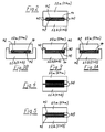
- FIG 1 the housing 10 of an apparatus traction or lifting is shown schematically.
- This housing has an inlet passage 12 through which the strap 14 enters inside the housing 10.
- the strap comes out of the device housing by an outlet (not shown) provided at the opposite end of the housing 10.
- the device is equipped with a walking lever forward 16 and a reverse lever 18 as well as a clutch release handle 20.
- a walking lever forward 16 and a reverse lever 18 as well as a clutch release handle 20.
- the forward lever 16 is mounted for pivoting around an axis 26 fixed relative to the casing 10.
- the forward lever 16 is connected by a connecting rod 28 to the jaw block before 22 and by a connecting rod 30 to the block rear jaw.
- the reverse lever 18 is pivotally connected to the front jaw block 22 and a connecting rod 32 is pivotally connected to the lever reverse 18 and rear jaw block 24.
- the release handle 20 is connected by a link 34 to the reverse lever 18.
- jaws 22a and 22b move away from the strap and the block front jaw 22 and moved backwards causing the two jaw blocks move closer together.
- the forward lever 16 is again pivoted to the right side clockwise around the axis 26 the movement of the jaws 22 and 24 is reversed, i.e. the jaws move away one from the other.
- the jaw block before 22 clamps now the strap to advance it to the left side while the rear jaw block 24 moves on the strap freely backwards.
- the jaws have a section simple rectangular cross.
- the jaws 22a, 22b, 24a, and 24b of each pair of jaws each have a U-shaped cross section with a 40 on each side of the clamping surface 42, the two forms in a U, in each grip of jaws, facing each other.
- a section housing flattened rectangular is made to receive the strap in the inner faces of the jaws. This housing allows the strap to be guided laterally between the jaws of the same pair.
- one 22b, 24b only of the jaws of a same pair is U-shaped, the other jaw 22a, 24a, of simple rectangular section being dimensioned for ability to lodge between branches of jaw U-shaped antagonist.
- one of the jaws 22b, 24b having a U shape the other jaw 22a, 24a of the same pair has a T shape obtained by lateral shoulders, the central part of the T fitting into the housing of the opposing U-shaped jaw.
- the two jaws 22a, 24a, 22b, 24b of the same pair are U-shaped and are face as in the embodiment of the figure 2 with the difference that one of the two jaws is wider than the other, so the latter can be accommodated in the tightening movement.
- the branches or jaw shoulders are sized in the tightening direction of the strap so that two opposing jaws never come to a stop against each other when the clamping movement of the strap 14 is brought to its maximum limit.
- FIG. 4 and 5 correspond to the embodiment of FIG. 2 except that according to the mode of execution of figure 4 of clamping pads of suitable materials 46 are provided between the opposing jaws 22a, 22b and 24a, 24b and strap 14 to ensure optimum grip between the jaws and the strap.
- the clamping surfaces 42 of the jaws 22a, 22b and 24a, 24b have imprints and / or reliefs 48 configured to optimize the cooperation of the jaws and strap.
- plates or footprints and / or reliefs can also be provided in the embodiment of Figures 3, 3A and 3B. Platelets may also have fingerprints and / or reliefs to allow optimal tightening of the strap.
- FIG. 6 represents a first mode of realization of a strap guide fixed on the jaw block upstream 24.
- This strap guide 50 comprises two pieces of guide 52 and 54.
- Each guide piece 52 and 54 has a head part attached by screws 56 to one of the jaws 22a, 22b of the rear jaw block 24 and includes a guide arm 50a, 50b extending axially and received in one of the jaws 22a, 22b of the front jaw block 22.
- the guide arms 50a, 50b of the strap guide 50 are slidably received in corresponding cavities 51a, 51b formed in the jaws 22a, 22b of the front jaw block 22 and are arranged respectively along each of the two wide sides of the strap 14 in its direction longitudinal so as to prohibit it from folding or looping movement between the two blocks jaws 22 and 24 when these approach one the other.
- This embodiment is also shown in Figure 1, see guide arms 50a, 50b of the rear jaws 24a, 24b, received in the passages made in the jaws before 22a and 22b.
- the upper jaws 22a, 24b slide on a fixed strap guide or runner 60 located on the upper side strap 14 while the jaws 22b, 24b slide on a strap guide or fixed slide similar 62 located on the lower side of the strap 14.
- the two slides 60 and 62 are fixed either to one either at the two ends of the casing 10 of the lifting or pulling.
- Backstage 60 and 62 are provided for the same purpose as the guide parts 52, 54 of the embodiment of FIG. 6, that is to say they serve to prevent strap 14 from moving fold or loop between the two jaw blocks 22 and 24 when these blocks approach each other.
- FIGS. 8A, 8B and 8C are views in cross section, along line 8-8 of figure 6, jaws 22a, 22b of the front jaw block 22. Tel that represented in FIG. 8A the cavities of sliding 51a, 51b for the guide arms 50a, 50b are laterally closed inside the jaws 22a, 22b and have a section corresponding to that of guide arm 50a, 50b.
- the cavities sliding 51a, 51b made in the jaws 22a, 22b for the guide arms 50a, 50b are formed by notches longitudinally open on the clamping surface 42 of the jaws 22a and 22b while according to figure 8B the section of the notch longitudinally open for sliding the jaws 22a, 22b on the guide arms 50a, 50b in cooperation with the guide arm section has a dovetail shape preventing the guide arm from escape from this gash.
- the cavities 60a, 62a formed in the jaws 22a, 22b and 24a, 24b of the embodiment of the Figure 7 for sliding mounting on the slides 60 and 62 can also be formed such that shown in Figures 8A, 8B and 8C.
Description
L'invention concerne un appareil de traction ou de levage d'un lien relié à une charge, fonctionnant par deux paires de mâchoires, à mouvement alternatif, notamment suivant le principe d'auto-serrage par la charge et, notamment également, pourvu d'un dispositif de pré-serrage hors charge et de débrayage simultané des deux paires de mâchoires.The invention relates to a traction device or lifting of a link connected to a load, operating by two pairs of jaws, reciprocating, in particular according to the principle of self-tightening by the load and, in particular also, provided with a pre-tightening device off load and simultaneous declutching of the two pairs of jaws.
On connaít des palans à mâchoires permettant le levage ou la descente d'une charge par un mécanisme de leviers actionnant deux paires de mâchoires dans un mouvement alternatif, l'une des paires de mâchoires se serrant sur un câble métallique, qui constitue un lien relativement peu souple, dans le sens de déplacement de la charge tandis que l'autre paire de mâchoires se desserre dans un mouvement inverse. De tels appareils sont décrits notamment dans le brevet français N° 914.400 sur lequel la forme en deux parties des revendications indépendantes est basée.We know jaws hoists allowing the lifting or lowering of a load by a mechanism levers operating two pairs of jaws in one reciprocating, one of the pairs of jaws tightening on a metal cable, which constitutes a link relatively inflexible, in the direction of movement of the load while the other pair of jaws loosens in a reverse movement. Such devices are described in particular in French patent N ° 914,400 on which the two-part form of the independent claims is based.
La demande de brevet français No. 2,252,280 concerne un dispositif permettant d'exercer une traction sur des câbles ou des filins présentant une certaine rigidité, tels que ceux qui sont couramment utilisés dans la navigation de plaisance. Le dispositif de traction a deux tubes de guidage du câble ou filin, engagé l'un dans l'autre et chacun porté par une plaque portant aussi un taquet coinceur à deux mâchoires. La demande de brevet allemand no. 37 31 383 concerne un dispositif de traction à câble ou bande flexible pourvu d'une enveloppe pour guider le câble ou la bande flexible entre les paires de mâchoires.French patent application No. 2,252,280 relates to a device for exerting traction on cables or ropes with a certain stiffness, such as those commonly used in pleasure cruising. The traction device has two cable or rope guide tubes, one engaged in the other and each carried by a plate also carrying a two-jaw cleat. The patent application German no. 37 31 383 relates to a traction device with flexible cable or strip provided with an envelope to guide the flexible cable or strip between the pairs of jaws.
La présente invention a pour objet d'appliquer un ensemble mécanique de même conception cinématique qu'indiqué ci-dessus, à la manoeuvre d'une sangle plate et souple utilisée comme lien pour le déplacement d'une charge.The object of the present invention is to apply a mechanical assembly with the same kinematic design as indicated above, when operating a flat strap and flexible used as a link for moving a charge.
Selon une première réalisation de l'invention l'appareil de traction et de levage est caractérisé en ce que lesdites paires de mâchoires dotées de surfaces de serrage plates correspondant aux faces larges d'une sangle souple à profil plat sont complétées par deux guides disposés respectivement le long de chacune des deux faces larges de la sangle et suivant sa direction longitudinale, de façon à interdire à celle-ci un mouvement de pliure ou de boucle entre les deux paires de mâchoires lorsque celles-ci se rapprochent l'une de l'autre, et en ce que chacune des deux mâchoires d'une première paire des deux paires de mâchoires est pourvue d'une cavité aménagée longitudinalement dans ces mâchoires, et l'un des deux guides est fixé à l'une des mâchoires de l'autre paire des deux paires de mâchoires et l'autre guide est fixé à l'autre mâchoire de l'autre paire des deux paires de mâchoires, le guide situé sur l'un des côtés de la sangle étant reçu à coulissement dans la cavité de la mâchoire, située sur le même côté de la sangle, de la première paire des deux paires de mâchoires alors que l'autre guide est reçu à coulissement dans la cavité de l'autre mâchoire de la première paire de mâchoires.According to a first embodiment of the invention the traction and lifting device is characterized in that that said pairs of jaws having surfaces of flat tightening corresponding to the wide sides of a strap flexible flat profile are supplemented by two guides arranged respectively along each of the two faces wide of the strap and in its longitudinal direction, so as to prevent it from bending or loop between the two pairs of jaws when these approach each other, and in that each of the two jaws of a first pair of the two pairs of jaws is provided with a fitted cavity longitudinally in these jaws, and one of the two guides is attached to one of the jaws of the other pair of two pairs of jaws and the other guide is attached to the other jaw of the other pair of the two pairs of jaws, the guide located on one side of the strap being received sliding in the cavity of the jaw, located on the same side of the strap, from the first pair of the two pairs of jaws while the other guide is received sliding in the cavity of the other jaw the first pair of jaws.
Comme la plupart des sangles, et notamment les sangles tissées, sont relativement souples, la sangle peut se plier dans sa partie comprise entre les deux paires de mâchoires, lorsque celles-ci se rapprochent l'une de l'autre. Les guides disposés selon l'invention le long de chaque face large de la sangle, parallèlement à son axe longitudinal interdisent ce pliage.Like most straps, especially woven straps, are relatively flexible, the strap can fold in its part between the two pairs of jaws, when these approach one of the other. The guides arranged according to the invention along each wide side of the strap, parallel to its axis longitudinal prohibit this folding.
Ces guides sont fixés de façon à tenir leur position et leur fonction sur une longueur comprise entre les deux paires de mâchoires, au moins égale à leur plus grand éloignement mutuel, sans gêner le serrage des mâchoires ni leur translation.These guides are fixed so as to hold their position and their function over a length between the two pairs of jaws, at least equal to their most great mutual distance, without hindering the tightening of jaws nor their translation.
Les deux guides sont constamment au contact, ou quasiment au contact de la sangle afin d'interdire tout désordre dans son mouvement, et ne s'interposent pas entre les faces internes des mâchoires et la sangle. Ils sont positionnés sur le trajet longitudinal des mâchoires sans gêner le mouvement de translation de celles-ci et sans que leur mouvement de serrage n'applique une pression des guides sur la sangle.The two guides are constantly in contact, or almost in contact with the strap to prevent everything disorder in its movement, and do not stand between the inner faces of the jaws and the strap. They are positioned on the longitudinal path of the jaws without hinder the translational movement of these and without their tightening movement only applies pressure from guides on the strap.
Deux au moins des quatre mâchoires, non situées du même côté de la sangle, coulissent sur le guide situé de leur côté par rapport à la sangle, par le moyen de cavités longitudinales aménagées dans ces mâchoires et de section correspondant à celle dudit guide, cependant que l'autre extrémité de chaque guide sera fixée à la mâchoire de l'autre paire.At least two of the four jaws, not located on the same side of the strap, slide on the guide located their side with respect to the strap, by means of cavities longitudinal arranged in these jaws and of section corresponding to that of said guide, while the other end of each guide will be attached to the jaw of the other pair.
Pour des raisons évidentes de construction, il est entendu qu'un guide ne peut être fixé à la fois sur les deux mâchoires situées du même côté de la sangle.For obvious construction reasons, it it is understood that a guide cannot be fixed at the same time on the two jaws located on the same side of the strap.
Selon une deuxième réalisation de l'invention l'appareil de traction et de levage est caractérisé par en ce que lesdites paires de mâchoires dotées de surfaces de serrage plates correspondant aux faces larges d'une sangle souple à profil plat sont complétées par deux guides disposés respectivement le long de chacune des deux faces larges de la sangle et suivant sa direction longitudinale, de façon à interdire à celle-ci un mouvement de pliure ou de boucle entre les deux paires de mâchoires lorsque celles-ci se rapprochent l'une de l'autre, et en ce que les guides sont fixés soit à l'une soit aux deux extrémités du carter de l'appareil, et les mâchoires, situées sur l'un des côtés de la sangle, des deux paires de mâchoires sont montées à coulissement sur le guide situé du même côté de la sangle, alors que dans les autres mâchoires des deux paires de mâchoires sont montées à coulissement sur l'autre guide.According to a second embodiment of the invention the traction and lifting device is characterized by what said pairs of jaws having surfaces of flat tightening corresponding to the wide sides of a strap flexible flat profile are supplemented by two guides arranged respectively along each of the two faces wide of the strap and in its longitudinal direction, so as to prevent it from bending or loop between the two pairs of jaws when these approach each other, and in that the guides are attached to either one or both ends of the device housing, and the jaws, located on one sides of the strap, two pairs of jaws are sliding mounted on the guide located on the same side of the strap, while in the other jaws of the two pairs of jaws are slidably mounted on each other guide.
La cavité longitudinale des mâchoires pourra être fermée latéralement à l'intérieur de la mâchoire, ou être ouverte latéralement sur la face interne de la mâchoire ou d'une plaquette de serrage de celle-ci. The longitudinal cavity of the jaws may be closed laterally inside the jaw, or be open laterally on the internal face of the jaw or a clamping plate thereof.
Dans ce dernier cas, la section de la cavité pourra avoir une forme appropriée telle qu'une queue d'aronde, en coopération avec une forme correspondante de la section du guide, empêchant celui-ci d'échapper latéralement de son logement.In the latter case, the section of the cavity may have an appropriate shape such as a tail dovetail, in cooperation with a corresponding shape of the guide section, preventing the guide from escaping laterally from its housing.
Dans tous les cas, l'action de serrage des mâchoires sur la sangle de devra pas entraíner de pression positive du guide contre la sangle.In all cases, the tightening action of the jaws on the strap should not lead to positive pressure of the guide against the strap.
On voit donc que les tiges-guides servent de guide à la fois pour la sangle et pour les mâchoires.We therefore see that the guide rods serve as guide for both the strap and the jaws.
Les côtés des mâchoires munis des surfaces de serrage peuvent être plats, mais afin de caler latéralement la sangle dans chaque paire de mâchoires, l'une des mâchoires ou les deux mâchoires de chaque paire peuvent comporter deux relevés latéraux bordant les surfaces de serrage. Selon un autre mode de réalisation l'une des mâchoires avec ou sans relevés latéraux vient se positionner à l'intérieur de sa mâchoire antagoniste comportant des relevés latéraux, de façon à former avec elle un encadrement pour la sangle.The sides of the jaws with the surfaces clamps can be flat, but in order to wedge laterally the strap in each pair of jaws, one of the jaws or both jaws of each pair may have two side flanks bordering clamping surfaces. According to another mode of realization of one of the jaws with or without raised side is positioned inside its opposing jaw with lateral raised, so as to form with it a frame for the strap.
On peut prévoir des plaquettes de serrage en matière appropriée fixées sur les faces internes des mâchoires pour réaliser les conditions d'adhérence optimum entre mâchoire et sangle.We can provide clamping plates in suitable material attached to the inner faces of jaws to achieve grip conditions optimum between jaw and strap.
En outre, la face interne des mâchoires ou de leurs plaquettes de serrage peut comporter des empreintes ou reliefs pour améliorer la coopération des mâchoires et de la sangle.In addition, the inner side of the jaws or of their clamping plates may include footprints or reliefs to improve cooperation between jaws and strap.
L'appareil de traction ou de levage sera
maintenant expliqué en plus grand détail en référence
aux figures annexées, sur lesquelles:
Sur la figure 1 le carter 10 d'un appareil
de traction ou de levage est représenté schématiquement.
Ce carter a un passage d'entrée 12 par lequel la sangle
14 pénètre à l'intérieur du carter 10. La sangle sort du
carter de l'appareil par une sortie (non représentée)
prévue à l'extrémité opposée du carter 10.In Figure 1 the
L'appareil est équipé d'un levier de marche
avant 16 et d'un levier de marche arrière 18 ainsi que
d'une poignée de debrayage 20. A l'intérieur du carter
10 sont disposés deux blocs mâchoires 22, 24 comportant
chacun deux mâchoires 22a, 22b respectivement 24a, 24b.
Le levier de marche avant 16 est monté pour pivotement
autour d'un axe 26 fixe par rapport au carter 10. Le
levier de marche avant 16 est relié par une bielle 28 au
bloc mâchoire avant 22 et par une bielle 30 au bloc
mâchoire arrière. Le levier de marche arrière 18 est
relié de façon pivotable au bloc mâchoire avant 22 et
une bielle 32 est reliée à pivotement au levier de
marche arrière 18 et au bloc mâchoire arrière 24. La
poignée de débrayage 20 est reliée par une biellette 34
au levier de marche arrière 18.The device is equipped with a walking lever
forward 16 and a
La construction d'un appareil de traction ou
de levage décrite ci-avant, ainsi que son
fonctionnement, sont bien connus dans l'état de la
technique des appareils pour la manoeuvre d'un câble
métallique et n'ont pas besoin d'être décrits ici en
plus grand détail. La différence entre l'appareil de
traction ou de levage selon la présente invention, et
l'appareil de l'état de la technique réside dans la
forme et la construction des blocs mâchoires conçus,
selon la présente invention, pour coopérer avec la
sangle flexible 14 au lieu du câble métallique. Il
suffit de mentionner ici que par pivotement du levier de
marche avant 16 la sangle 14 est avancée vers le côté
gauche. Lorsque le levier 16 est pivoté dans le sens
contraire au mouvement des aiguilles d'une montre les
deux mâchoires 24a et 24b du bloc mâchoire arrière 24
serrent la sangle entre elles et se déplacent avec la
sangle vers l'avant ou le côté gauche. En même temps les
mâchoires 22a et 22b s'écartent de la sangle et le bloc
mâchoire avant 22 et déplacé vers l'arrière faisant que
les deux blocs mâchoires se rapprochent. Lorsque le
levier de marche avant 16 est de nouveau pivoté vers le
côté droit dans le sens des aiguilles d'une montre
autour de l'axe 26 le mouvement des mâchoires 22 et 24
est inversé, c'est-à-dire les mâchoires s'éloignent
l'une de l'autre. Le bloc mâchoire avant 22 serre
maintenant la sangle pour l'avancer vers le côté gauche
alors que le bloc mâchoire arrière 24 se déplace sur la
sangle librement vers l'arrière.The construction of a traction device or
described above, as well as its
are well known in the state of
technical devices for cable operation
metallic and need not be described here in
greater detail. The difference between the
traction or lifting according to the present invention, and
the state of the art apparatus resides in the
shape and construction of the designed jaw blocks,
according to the present invention, to cooperate with the
Lorsque le levier de marche arrière 18 est
pivoté autour de son pivot le reliant au bloc mâchoire
avant 22 vers l'avant dans le sens contraire au
mouvement des aiguilles d'une montre les deux mâchoires
22 et 24 se rapprochent l'une de l'autre, le bloc
mâchoire avant 22 serrant la sangle pour la déplacer
vers le côté droit alors que le bloc mâchoire arrière 24
glisse sur la sangle. Les deux blocs mâchoires 22 et 24
sont déplacés en directions opposées lorsque le levier
de marche arrière 18 est pivoté dans le sens opposé,
c'est-à-dire dans la direction de mouvement des
aiguilles d'une montre. Les deux blocs mâchoires 22 et
24 s'éloignent maintenant l'une de l'autre, la sangle
étant coincée dans le bloc mâchoire 24 et le bloc
mâchoire 22 glissant sur la sangle en s'éloignant du
bloc mâchoire 24. Pour introduire la sangle 14 dans
l'appareil de levage ou de traction, les deux blocs
mâchoires 22 et 24 doivent être amenés en position
ouverte. Cela est réalisé en poussant la poignée de
débrayage 20 vers le côté gauche qui agit par
l'intermédiaire de la biellette 34, du levier de marche
arrière 18 et de la bielle 32 sur les deux blocs
mâchoires 22 et 24 en vue de les ouvrir. Un appareil de
traction ou de levage selon la construction décrite ci-avant,
à l'exception des mâchoires conçues pour
coopération avec une sangle flexible, est connu dans
l'état de la technique.When the
Dans la forme de réalisation la plus simple (non-représentée), les mâchoires ont une section transversale rectangulaire simple.In the simplest embodiment (not shown), the jaws have a section simple rectangular cross.
Selon la figure 2, les mâchoires 22a, 22b,
24a, et 24b de chaque paire de mâchoires ont chacune une
section transversale en forme de U avec un relevé 40 sur
chaque côté de la surface de serrage 42, les deux formes
en U, dans chaque prise de mâchoires, se faisant face.According to FIG. 2, the jaws 22a, 22b,
24a, and 24b of each pair of jaws each have a
U-shaped cross section with a 40 on
each side of the
De cette façon, un logement de section rectangulaire aplatie est pratiqué pour recevoir la sangle dans les faces internes des mâchoires. Ce logement permet de guider la sangle latéralement entre les mâchoires d'une même paire.In this way, a section housing flattened rectangular is made to receive the strap in the inner faces of the jaws. This housing allows the strap to be guided laterally between the jaws of the same pair.
Selon une variante représentée dans la figure 3A, l'une 22b, 24b seulement des mâchoires d'une même paire est en forme de U, l'autre mâchoire 22a, 24a, de section rectangulaire simple étant dimensionnée pour pouvoir se loger entre les branches de la mâchoire antagoniste en forme de U.According to a variant shown in the Figure 3A, one 22b, 24b only of the jaws of a same pair is U-shaped, the other jaw 22a, 24a, of simple rectangular section being dimensioned for ability to lodge between branches of jaw U-shaped antagonist.
Selon un autre mode d'exécution, représenté dans la figure 3, l'une des mâchoires 22b, 24b ayant une forme de U, l'autre mâchoire 22a, 24a de la même paire a une forme de T obtenue par des épaulements latéraux, la partie centrale du T venant s'emboíter dans le logement de la mâchoire antagoniste en forme de U. According to another embodiment, shown in FIG. 3, one of the jaws 22b, 24b having a U shape, the other jaw 22a, 24a of the same pair has a T shape obtained by lateral shoulders, the central part of the T fitting into the housing of the opposing U-shaped jaw.
Selon un quatrième mode de réalisation, représenté par la figure 3B, les deux mâchoires 22a, 24a, 22b, 24b d'une même paire sont en forme de U et se font face comme dans le mode de réalisation de la figure 2 avec la différence que l'une des deux mâchoires est plus large que l'autre, de sorte que cette dernière puisse venir s'y loger dans le mouvement de serrage.According to a fourth embodiment, represented by FIG. 3B, the two jaws 22a, 24a, 22b, 24b of the same pair are U-shaped and are face as in the embodiment of the figure 2 with the difference that one of the two jaws is wider than the other, so the latter can be accommodated in the tightening movement.
Dans les différents cas de figure ci-dessus
formant logement pour la sangle 14, les branches ou
épaulements de mâchoire sont dimensionnés dans la
direction de serrage de la sangle de façon telle que
deux mâchoires antagonistes ne viennent jamais en butée
l'une contre l'autre lorsque le mouvement de serrage de
la sangle 14 est porté à sa limite maximum.In the different cases above
forming a housing for the
Les modes de réalisation selon les figures 4
et 5 correspondent au mode d'exécution de la figure 2
sauf que selon le mode d'exécution de la figure 4 des
plaquettes de serrage de matériaux appropriés 46 sont
prévues entre les mâchoires opposées 22a, 22b et 24a,
24b et la sangle 14 pour assurer une adhérence optimum
entre les mâchoires et la sangle. Selon la figure 5 les
surfaces de serrage 42 des mâchoires 22a, 22b et 24a,
24b comportent des empreintes et/ou des reliefs 48
configurés pour optimiser la cooperation des mâchoires
et de la sangle. Bien entendu de telles plaquettes ou
des empreintes et/ou de reliefs peuvent aussi être
prévus dans le mode d'exécution des figures 3, 3A et 3B.
Les plaquettes peuvent aussi avoir des empreintes et/ou
des reliefs pour permettre un serrage optimal de la
sangle.The embodiments according to Figures 4
and 5 correspond to the embodiment of FIG. 2
except that according to the mode of execution of figure 4 of
clamping pads of
La figure 6 représente un premier mode de
réalisation d'un guide-sangle fixé sur le bloc mâchoire
amont 24. Ce guide-sangle 50 comporte deux pièces de
guidage 52 et 54. Chaque pièce de guidage 52 et 54 a une
partie de tête attachée par des vis 56 à l'une des
mâchoires 22a, 22b du bloc mâchoire arrière 24 et
comporte un bras de guidage 50a, 50b s'étendant
axialement et reçu dans l'une des mâchoires 22a, 22b du
bloc mâchoire avant 22. Les bras de guidage 50a, 50b du
guide-sangle 50 sont reçues à coulissement dans des
cavités correspondantes 51a, 51b pratiquées dans les
mâchoires 22a, 22b du bloc mâchoire avant 22 et sont
disposés respectivement le long de chacune des deux
faces larges de la sangle 14 suivant sa direction
longitudinale de façon à interdire à celle-ci un
mouvement de pliure ou de boucle entre les deux blocs
mâchoires 22 et 24 lorsque ceux-ci se rapprochent l'un
de l'autre. Ce mode de réalisation est également
représenté sur la figure 1, voir les bras de guidage
50a, 50b des mâchoires arrières 24a, 24b, reçues dans
les passages pratiqués dans les mâchoires avant 22a et
22b.FIG. 6 represents a first mode of
realization of a strap guide fixed on the jaw block
upstream 24. This strap guide 50 comprises two pieces of
Selon le mode de réalisation de la figure 7
les mâchoires supérieures 22a, 24b coulissent sur un
guide-sangle ou coulisse fixe 60 situé du côté supérieur
de la sangle 14 alors que les mâchoires 22b, 24b
coulissent sur un guide-sangle ou coulisse fixe
semblable 62 situé du côté inférieur de la sangle 14.
Les deux coulisses 60 et 62 sont fixées soit à l'une
soit aux deux extrémités du carter 10 de l'appareil de
levage ou de traction. Les coulisses 60 et 62 sont
prévues pour le même but que les pièces de guidage 52,
54 du mode d'exécution de la figure 6, c'est-à-dire
elles servent à interdire à la sangle 14 un mouvement de
pliure ou de boucle entre les deux blocs de mâchoires 22
et 24 lors que ces blocs se rapprochent l'un de l'autre.According to the embodiment of Figure 7
the upper jaws 22a, 24b slide on a
fixed strap guide or
Les figures 8A, 8B et 8C sont des vues en
coupe transversale, le long de la ligne 8-8 de la figure
6, des mâchoires 22a, 22b du bloc mâchoire avant 22. Tel
que représenté sur la figure 8A les cavités de
coulissement 51a, 51b pour les bras de guidage 50a, 50b
sont latéralement fermés à l'intérieur des mâchoires
22a, 22b et ont une section correspondante à celle des
bras de guidage 50a, 50b. Selon la figure 8C les cavités
de coulissement 51a, 51b pratiquées dans les mâchoires
22a, 22b pour les bras de guidage 50a, 50b sont formées
par des entailles longitudinalement ouvertes sur les
surface de serrage 42 des mâchoires 22a et 22b alors que
selon la figure 8B la section de l'entaille
longitudinalement ouverte pour le coulissement des
mâchoires 22a, 22b sur les bras de guidage 50a, 50b en
coopération avec la section du bras de guidage a une
forme en queue d'arronde empêchant le bras de guidage de
s'échapper de cette entaille.FIGS. 8A, 8B and 8C are views in
cross section, along line 8-8 of figure
6, jaws 22a, 22b of the
Les cavités 60a, 62a pratiquées dans les
mâchoires 22a, 22b et 24a, 24b du mode d'exécution de la
figure 7 pour le montage à coulissement sur les
coulisses 60 et 62 peuvent aussi être formées tel que
représenté sur les figures 8A, 8B et 8C.The
Claims (9)
- Traction or lifting device of a tie connected to a load, operating by two pairs of jaws (22a, 22b; 24a, 24b), of alternating movement, especially according to the principle of automatic gripping by the load and, in particular, also provided with a means (20) for pre-clamping under no load and for simultaneously unclamping the two pairs of jaws (22a, 22b; 24a, 24b), characterized in that said pairs of jaws (22a, 22b; 24a, 24b) provided with flat clamping surfaces (42) corresponding to the wide faces of a flexible strap (14) of flat profile are completed by two guides (50a, 50b) disposed along each of the two wide faces, respectively, of the strap (14) and along its longitudinal direction, so as to prevent the strap forming a fold or loop between the two pairs of jaws (22a, 22b; 24a, 24b) when said pairs of jaws move towards one another, and in that each of the two jaws (22a, 22b) of a first pair of the two pairs of jaws is provided with a cavity (51a, 51b) formed longitudinally within said jaws (22a, 22b), and one (50a) of the two guides (50a, 50b) is fixed to one of the jaws (24a) of the other pair of the two pairs of jaws and the other guide (50b) is fixed to the other jaw (24b) of the other pair of the two pairs of jaws, the guide located on one of the sides of the strap being slidably received in the cavity of the jaw (22a), located on the same side of the strap, of the first pair of the two pairs of jaws while the other guide (50b) is slidably received in the cavity of the other jaw (22b) of the first pair of jaws (22a, 22b).
- Traction or lifting device of a tie connected to a load, operating by two pairs of jaws (22a, 22b; 24a, 24b) of alternating movement, especially according to the principle of automatic gripping by the load and, in particular, also provided with a means (20) for pre-clamping under no load and for simultaneously unclamping the two pairs of jaws (22a, 22b; 24a, 24b), characterized in that said pairs of jaws (22a, 22b; 24a, 24b) provided with flat clamping surfaces (42) corresponding to the wide faces of a flexible strap (14) of flat profile are completed by two guides (60, 62) disposed along each of the two wide faces, respectively, of the strap (14) and along its longitudinal direction, so as to prevent the strap forming a fold or loop between the two pairs of jaws (22a, 22b; 24a, 24b) when said pairs of jaws move towards one another, and in that the guides (60, 62) are attached to one or to both extremities of the housing (10) of the device, and the jaws (22a, 24a), located on one of the sides of the strap, of the two pairs of jaws are slidably mounted on the guide (60) located on the same side of the strap while the other jaws (22b, 24b) of the two pairs of jaws are slidably mounted on the other guide (62), said guides (60, 62) passing through slide cavities (60a, 62a) in the jaws (22a, 22b; 24a, 24b).
- Device according to claim 1 or 2, characterized in that one of the jaws of the two jaws of each pair of jaws (22a, 22b; 24a, 24b) comprise two lateral raised sections (40) bordering the clamping surfaces (42).
- Device according to any one of claims 1 to 3, characterized in that one of the jaws (22a, 24b) is received in its opposing jaw (22b; 24b) having lateral raised sections (40) to form therewith an enclosure for the passage or the clamping of the strap (14) located therein.
- Device according to any one of claims 1 through 4, characterized in that shims (46) of appropriate material for providing optimum adhesion between the jaw and the strap are fixed to the inner surface of the jaws (22a, 22b; 24a, 24b).
- Device according to any one of claims 1 through 5, characterized in that the clamping surface (42) of the jaws (22a, 22b; 24a, 24b) or of the shims (46) thereof comprise indentations and/or elevations (48) configured to optimise the cooperation of the jaws (22a, 22b; 24a, 24b) and the strap (14).
- Device according to any one of claims 1 to 6, characterized in that the slide cavity (51a, 51b; 60a, 62a) of the jaws (22a, 22b; 24a, 24b) is laterally closed within the interior of the jaws by having a cross-section corresponding to that of the guide (50a, 50b; 60, 62).
- Device according to any one of claims 1 to 6, characterized in that the slide cavity (51a, 51b; 60a, 62a) of the jaws (22a, 22b; 24a, 24b) is a slot which is longitudinally open on the internal face of said jaws (22a, 22b; 24a, 24b).
- Device according to claim 8, characterized in that the cross-section of the slot, in cooperation with the cross-section of the guide (50a, 50b; 60, 62) has a shape preventing the guide (50a, 50b; 60, 62) to disengage said slot.
Applications Claiming Priority (2)
| Application Number | Priority Date | Filing Date | Title |
|---|---|---|---|
| FR9408860A FR2722489B1 (en) | 1994-07-18 | 1994-07-18 | JAW LIFTING OR TRACTION APPARATUS ACTING ON FLEXIBLE STRAPS WITH A FLAT PROFILE |
| FR9408860 | 1994-07-18 |
Publications (2)
| Publication Number | Publication Date |
|---|---|
| EP0693455A1 EP0693455A1 (en) | 1996-01-24 |
| EP0693455B1 true EP0693455B1 (en) | 1999-12-29 |
Family
ID=9465481
Family Applications (1)
| Application Number | Title | Priority Date | Filing Date |
|---|---|---|---|
| EP95630085A Expired - Lifetime EP0693455B1 (en) | 1994-07-18 | 1995-07-18 | Traction or lifting device with jaws, acting on low profile flexible straps |
Country Status (6)
| Country | Link |
|---|---|
| US (1) | US5655754A (en) |
| EP (1) | EP0693455B1 (en) |
| CN (1) | CN1121480A (en) |
| DE (1) | DE69514161T2 (en) |
| ES (1) | ES2141319T3 (en) |
| FR (1) | FR2722489B1 (en) |
Families Citing this family (5)
| Publication number | Priority date | Publication date | Assignee | Title |
|---|---|---|---|---|
| US6488267B1 (en) * | 2000-09-12 | 2002-12-03 | The United States Of America As Represented By The Secretary Of The Army | Apparatus for lifting or pulling a load |
| US8020835B2 (en) * | 2007-11-02 | 2011-09-20 | Lockheed Martin Corporation | Device for installing and removing high insertion force modules |
| WO2011001502A1 (en) * | 2009-06-30 | 2011-01-06 | 株式会社永木精機 | Wire gripper |
| CN106882708B (en) * | 2017-02-13 | 2018-02-16 | 太原理工大学 | A kind of perpendicular lifting apparatus and method |
| CN107618808A (en) * | 2017-10-31 | 2018-01-23 | 山西新格机电科技有限公司 | A kind of fully automatic hydraulic conveyer belt clamps pulling equipment |
Family Cites Families (13)
| Publication number | Priority date | Publication date | Assignee | Title |
|---|---|---|---|---|
| FR914400A (en) | 1945-09-05 | 1946-10-07 | Wire rope pulling and lifting device | |
| US2990091A (en) * | 1953-01-13 | 1961-06-27 | Glastrusions | Apparatus for feeding plastic bars, tubes and like elongated stock |
| FR1342298A (en) * | 1962-09-27 | 1963-11-08 | Self-tightening pliers for traction and lifting apparatus as well as traction and lifting apparatus provided with said self-tightening pliers or the like | |
| FR1513335A (en) * | 1966-10-25 | 1968-02-16 | Tractel S A Soc | Device for pre-tightening the jaws of pliers acting on a cable with self-tightening effect |
| BE792753A (en) * | 1971-12-15 | 1973-03-30 | Milbras S P R L | SELF-TIGHTENING PLIERS FOR A FREE WIRE WINCH |
| FR2290385A2 (en) * | 1973-11-23 | 1976-06-04 | Doucin Michel | Cable traction device - has telescopic tubes on fixed and slidable stops on common slide |
| FR2252280A1 (en) * | 1973-11-23 | 1975-06-20 | Doucin Michel | Rope and cable winch - has two gripping blocks alternately gripping rope and alternately sliding towards and away from each other |
| DE2928028A1 (en) * | 1979-07-11 | 1981-01-29 | Rutzki Geb Wilke Edith | TENSION LOCK FOR BELT TAPES |
| DE3168444D1 (en) * | 1981-05-13 | 1985-03-07 | Secalt | Device for gripping and/or longitudinally moving an elongated traction member |
| US4483517A (en) * | 1982-04-01 | 1984-11-20 | Secalt S.A. | Tractive apparatus for hauling a cable, a bar or a similar member |
| FR2524454A1 (en) * | 1982-04-01 | 1983-10-07 | Tractel Sa | TENSION APPARATUS FOR HAULING A CABLE, BAR OR COMPARABLE BODY |
| DD233744A3 (en) * | 1984-01-24 | 1986-03-12 | Bauakademie Ddr | HYDRAULIC PULLING DEVICE |
| DE3731383A1 (en) * | 1987-09-18 | 1989-04-06 | Kreiss Burkhard | Rope hauling device |
-
1994
- 1994-07-18 FR FR9408860A patent/FR2722489B1/en not_active Expired - Fee Related
-
1995
- 1995-07-13 US US08/502,096 patent/US5655754A/en not_active Expired - Fee Related
- 1995-07-18 EP EP95630085A patent/EP0693455B1/en not_active Expired - Lifetime
- 1995-07-18 CN CN95108437A patent/CN1121480A/en active Pending
- 1995-07-18 DE DE69514161T patent/DE69514161T2/en not_active Expired - Fee Related
- 1995-07-18 ES ES95630085T patent/ES2141319T3/en not_active Expired - Lifetime
Also Published As
| Publication number | Publication date |
|---|---|
| DE69514161D1 (en) | 2000-02-03 |
| DE69514161T2 (en) | 2000-08-24 |
| FR2722489A1 (en) | 1996-01-19 |
| EP0693455A1 (en) | 1996-01-24 |
| CN1121480A (en) | 1996-05-01 |
| ES2141319T3 (en) | 2000-03-16 |
| FR2722489B1 (en) | 1996-08-30 |
| US5655754A (en) | 1997-08-12 |
Similar Documents
| Publication | Publication Date | Title |
|---|---|---|
| FR2658108A1 (en) | FAST ACTING CLAMPING DEVICE. | |
| EP0448484A1 (en) | Protective covering for a linear guide module for translation and manipulation of pieces and accessories | |
| FR2635289A1 (en) | FAST ACTION TANK | |
| FR2658107A1 (en) | TOOL HAND TIGHTENING. | |
| EP0058375B1 (en) | Crimping pliers | |
| FR2585610A1 (en) | TRACTION AND CUTTING CLAMP FOR LANIERE, ESPECIALLY FOR CLAMPING NECK | |
| EP0693455B1 (en) | Traction or lifting device with jaws, acting on low profile flexible straps | |
| EP0958896A1 (en) | Multifunction pocket tool with a plier | |
| EP0074371B1 (en) | Improvement to clamping pliers | |
| FR2597060A1 (en) | FRONT DERAILLEUR FOR A BICYCLE | |
| EP0401099B1 (en) | Apparatus for driving a load carrying strap with a coordinated device for deflection of the load and guiding of the strap | |
| CH622459A5 (en) | Pulling and cutting pliers for a thin strip, in particular that of a clamping collar | |
| FR2945229A1 (en) | GRIPPING TOOLS MANUALLY ACTUATED | |
| FR2672881A1 (en) | CLAMP FOR LIFTING FLAT ELEMENTS, SUCH AS PACKAGES OF SHEETS. | |
| FR2611650A1 (en) | DEVICE FOR TIETING A FLEXIBLE LINK | |
| EP0136189B1 (en) | Device for retrieving containers such as storage bins | |
| FR2500344A1 (en) | Scissor-action jack-actuated sheet metal shears - has centre blade between pair of counter blades with fulcrum tied to jack case | |
| EP0092455A1 (en) | Traction apparatus for hauling a cable, a bar or a comparable element | |
| FR2524454A1 (en) | TENSION APPARATUS FOR HAULING A CABLE, BAR OR COMPARABLE BODY | |
| EP1375046B1 (en) | Portable spot welding gun | |
| FR2610562A1 (en) | Articulated handling gripper with five degrees of freedom | |
| EP1280632B1 (en) | Reducer pliers | |
| FR2640605A1 (en) | Self-tightening mechanical grip | |
| FR2585608A1 (en) | GRIPPING DEVICE | |
| FR2669861A1 (en) | OPERATION DEVICE FOR A SUNROOF OF A MOTOR VEHICLE. |
Legal Events
| Date | Code | Title | Description |
|---|---|---|---|
| PUAI | Public reference made under article 153(3) epc to a published international application that has entered the european phase |
Free format text: ORIGINAL CODE: 0009012 |
|
| AK | Designated contracting states |
Kind code of ref document: A1 Designated state(s): CH DE ES GB LI |
|
| 17P | Request for examination filed |
Effective date: 19960530 |
|
| 17Q | First examination report despatched |
Effective date: 19980827 |
|
| GRAG | Despatch of communication of intention to grant |
Free format text: ORIGINAL CODE: EPIDOS AGRA |
|
| GRAG | Despatch of communication of intention to grant |
Free format text: ORIGINAL CODE: EPIDOS AGRA |
|
| GRAG | Despatch of communication of intention to grant |
Free format text: ORIGINAL CODE: EPIDOS AGRA |
|
| GRAH | Despatch of communication of intention to grant a patent |
Free format text: ORIGINAL CODE: EPIDOS IGRA |
|
| GRAH | Despatch of communication of intention to grant a patent |
Free format text: ORIGINAL CODE: EPIDOS IGRA |
|
| GRAA | (expected) grant |
Free format text: ORIGINAL CODE: 0009210 |
|
| AK | Designated contracting states |
Kind code of ref document: B1 Designated state(s): CH DE ES GB LI |
|
| REG | Reference to a national code |
Ref country code: CH Ref legal event code: EP |
|
| REF | Corresponds to: |
Ref document number: 69514161 Country of ref document: DE Date of ref document: 20000203 |
|
| REG | Reference to a national code |
Ref country code: ES Ref legal event code: FG2A Ref document number: 2141319 Country of ref document: ES Kind code of ref document: T3 |
|
| GBT | Gb: translation of ep patent filed (gb section 77(6)(a)/1977) |
Effective date: 20000317 |
|
| PLBE | No opposition filed within time limit |
Free format text: ORIGINAL CODE: 0009261 |
|
| STAA | Information on the status of an ep patent application or granted ep patent |
Free format text: STATUS: NO OPPOSITION FILED WITHIN TIME LIMIT |
|
| 26N | No opposition filed | ||
| REG | Reference to a national code |
Ref country code: GB Ref legal event code: IF02 |
|
| PGFP | Annual fee paid to national office [announced via postgrant information from national office to epo] |
Ref country code: GB Payment date: 20030716 Year of fee payment: 9 |
|
| PGFP | Annual fee paid to national office [announced via postgrant information from national office to epo] |
Ref country code: DE Payment date: 20040713 Year of fee payment: 10 |
|
| PG25 | Lapsed in a contracting state [announced via postgrant information from national office to epo] |
Ref country code: GB Free format text: LAPSE BECAUSE OF NON-PAYMENT OF DUE FEES Effective date: 20040718 |
|
| GBPC | Gb: european patent ceased through non-payment of renewal fee |
Effective date: 20040718 |
|
| PG25 | Lapsed in a contracting state [announced via postgrant information from national office to epo] |
Ref country code: DE Free format text: LAPSE BECAUSE OF NON-PAYMENT OF DUE FEES Effective date: 20060201 |
|
| PGFP | Annual fee paid to national office [announced via postgrant information from national office to epo] |
Ref country code: ES Payment date: 20070727 Year of fee payment: 13 |
|
| PGFP | Annual fee paid to national office [announced via postgrant information from national office to epo] |
Ref country code: CH Payment date: 20070713 Year of fee payment: 13 |
|
| REG | Reference to a national code |
Ref country code: CH Ref legal event code: PL |
|
| PG25 | Lapsed in a contracting state [announced via postgrant information from national office to epo] |
Ref country code: LI Free format text: LAPSE BECAUSE OF NON-PAYMENT OF DUE FEES Effective date: 20080731 Ref country code: CH Free format text: LAPSE BECAUSE OF NON-PAYMENT OF DUE FEES Effective date: 20080731 |
|
| REG | Reference to a national code |
Ref country code: ES Ref legal event code: FD2A Effective date: 20080719 |
|
| PG25 | Lapsed in a contracting state [announced via postgrant information from national office to epo] |
Ref country code: ES Free format text: LAPSE BECAUSE OF NON-PAYMENT OF DUE FEES Effective date: 20080719 |