EP0693338A1 - Feuerfestes Verschlussteil für ein Verschlussorgan am Ausguss eines Metallschmelze enthaltenden Gefässes - Google Patents
Feuerfestes Verschlussteil für ein Verschlussorgan am Ausguss eines Metallschmelze enthaltenden Gefässes Download PDFInfo
- Publication number
- EP0693338A1 EP0693338A1 EP95110890A EP95110890A EP0693338A1 EP 0693338 A1 EP0693338 A1 EP 0693338A1 EP 95110890 A EP95110890 A EP 95110890A EP 95110890 A EP95110890 A EP 95110890A EP 0693338 A1 EP0693338 A1 EP 0693338A1
- Authority
- EP
- European Patent Office
- Prior art keywords
- stator
- refractory
- insert
- rotor
- opening
- Prior art date
- Legal status (The legal status is an assumption and is not a legal conclusion. Google has not performed a legal analysis and makes no representation as to the accuracy of the status listed.)
- Withdrawn
Links
- 239000002184 metal Substances 0.000 title claims abstract description 5
- 238000006073 displacement reaction Methods 0.000 claims abstract description 6
- 239000011819 refractory material Substances 0.000 claims description 3
- 229910000831 Steel Inorganic materials 0.000 description 7
- 239000010959 steel Substances 0.000 description 7
- 238000007654 immersion Methods 0.000 description 4
- 238000004519 manufacturing process Methods 0.000 description 3
- 239000003570 air Substances 0.000 description 1
- 239000012080 ambient air Substances 0.000 description 1
- QVGXLLKOCUKJST-UHFFFAOYSA-N atomic oxygen Chemical compound [O] QVGXLLKOCUKJST-UHFFFAOYSA-N 0.000 description 1
- 230000005540 biological transmission Effects 0.000 description 1
- 238000005266 casting Methods 0.000 description 1
- 229910010293 ceramic material Inorganic materials 0.000 description 1
- 238000009749 continuous casting Methods 0.000 description 1
- 238000009434 installation Methods 0.000 description 1
- 239000007788 liquid Substances 0.000 description 1
- 239000000155 melt Substances 0.000 description 1
- 239000004570 mortar (masonry) Substances 0.000 description 1
- 238000000465 moulding Methods 0.000 description 1
- 229910052760 oxygen Inorganic materials 0.000 description 1
- 239000001301 oxygen Substances 0.000 description 1
- 238000007789 sealing Methods 0.000 description 1
- 239000000161 steel melt Substances 0.000 description 1
- 239000000126 substance Substances 0.000 description 1
Images

Classifications
-
- B—PERFORMING OPERATIONS; TRANSPORTING
- B22—CASTING; POWDER METALLURGY
- B22D—CASTING OF METALS; CASTING OF OTHER SUBSTANCES BY THE SAME PROCESSES OR DEVICES
- B22D41/00—Casting melt-holding vessels, e.g. ladles, tundishes, cups or the like
- B22D41/14—Closures
Definitions
- the invention relates to a fireproof closure part for a closure member on the spout of a metal-containing vessel, which is designed as a stator which can be fastened in the spout or as a rotor rotatably guided therein via a cylindrical sliding surface, the stator having a central longitudinal opening and at least one transverse one emanating therefrom Opening, in which the rotor has at least one opening corresponding to the latter, and the overlap of these transverse openings can be changed by twisting and / or an axial longitudinal displacement of the rotor in order to open or close the closure member.
- a closure device in which the stator forms the container spout and is mortared into the refractory lining of the molten steel container or, more generally, is embedded.
- the rotor which is arranged coaxially with this stator, is rotatably placed at the lower end in a cylindrical opening of the stator and he extends above the vessel. In principle, the rotor could also have an opening into which the stator with a machined dome would be guided.
- a drive rod which also extends beyond the container, projects into a longitudinal opening in this rotor, which is positively connected to the rotor at the bottom in the direction of rotation and is coupled at the top to a rotary drive device.
- a transverse opening in the lower part of the rotor corresponds to that of the stator in its upper part and, when the two are covered, liquid steel flows from the container, for example a distributor vessel, through said openings and through the central opening in the stator into a mold Continuous caster.
- the stator could be designed so that it extends into the mold and would then be designed as a so-called immersion spout, which prevents the steel melt flowing from this container from being covered with the ambient air and therefore not being contaminated with oxygen or other substances.
- the refractory stator as well as the rotor are each made of a certain refractory material and it takes relatively complex shapes for their manufacture in order to be able to produce them with sufficient dimensional accuracy.
- the object of the present invention is to provide a fireproof closure part according to the type described at the outset, which is simple and therefore inexpensive to produce and with which an equivalent or even improved durability is achieved.
- the object is achieved in that the closure part has a refractory insert which at least partially forms the sliding surface.
- This refractory insert very advantageously forms the cylindrical part with the sliding surface sealingly coming into contact with the other closure part.
- the refractory closure part according to the invention With this design of the refractory closure part according to the invention, this can be produced significantly more easily than if it is formed in one piece.
- fine-grained ceramic material is usually filled into molds, pressed therein and subsequently fired in an oven to harden the molded part. Due to the two-part design of the closure part according to the invention, simple shapes can be built for this in the simplified manufacturing process.
- the insert on the outer cylindrical sliding surface can be machined very easily before assembly with the rest of the stator part.
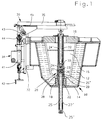
- FIG. 1 shows a vessel 10 containing metal melt 15 with a steel jacket 14 and a refractory lining 12 walled therein.
- a removable cover 16 is also placed on the top of the vessel 10, by means of which the melt is sealed from the outside air.
- a sleeve 18 serving as a spout is embedded in the refractory lining 12 on the underside of the vessel 10.
- a closure member 10 with a refractory stator 22 which can be fastened in the aforementioned sleeve 18 by means of mortar or the like as the one closure part and a refractory rotor 23 rotatably guided thereon as another closure part are arranged in this spout .
- the stator 22 extends from the inside of the vessel 10 through the spout and is outside it as a so-called immersion spout 22 ' trained, he protrudes into a mold, not shown, and enables a so-called hidden casting.
- the stator could also be made in two parts, the immersion pouring part 22 'being separate from the upper part of the stator.
- the stator 22 there is a central longitudinal opening 25, at the top a transverse opening 26 extending from this and at the bottom two side openings 25 'are provided through which the molten steel 15 advantageously flows into the mold of a continuous casting plant. Instead of four side openings 25 ', only two of them could be provided.
- this rotor 24 On its underside, this rotor 24 has a cylindrical recess with an advantageously concentric axis to that of the rotor 24, in which the stator 22 engages with an outer cylindrical sliding surface 27 in a sealing manner.
- An opening corresponding to the transverse opening 26 of the stator 22 is provided in the wall region of this recess in the rotor 24. which when covered - as shown - form a through opening between the inside of the vessel 10 and the longitudinal opening 25 of the stator 22 and therefore this closure member 20 is in the open position.
- the lower end face of the rotor 24 rests on one of the stator 22 and it is in rotary connection with a drive rod 32 projecting into it, which is coupled at its upper end to a drive unit 30.
- the rotor 24 has an opening 24 'at the top, which extends approximately to the aforementioned recess and has a polygon at the lower end, into which a polygonal head 33 of the drive rod 32 engages in a form-fitting manner as seen in the direction of rotation and consequently entrains when the same is rotated of the rotor.
- the polygonal head 33 is designed in such a way that the drive rod 32 can incline to the rotor axis by a few degrees, thus ensuring that the rotor and the drive rod do not have to be exactly aligned after installation in the vessel, and nevertheless a faultless transmission of rotation is ensured.
- the stator 22 has a refractory insert 23 as the closure part, which forms the entire sliding surface 27 and the transverse opening 26 thereof.
- This insert 23 therefore forms the upper cylindrical part of the stator 22 and has a coaxial opening 25 ′′, which overlaps the longitudinal opening 25 of the stator 22 and merges into the transverse opening 26 at the top.
- the insert 23 is expediently inserted into a recess 29 on the upper end face of the stator part and is mortar-locked therein.
- the anti-rotation device is provided via at least one lateral inclined surface or via a polygonal design of the insert 23 and the stator part in the area that engages against one another.
- the drive unit 30 mainly functions in a manner known per se and it is therefore not explained in every detail. It essentially comprises a support 32 which can be attached laterally to the vessel 10, a linear displacement element 34 arranged vertically thereon, and a cantilever arm 35 which extends from the latter and extends horizontally above the vessel and with the rotating part 36 of which the drive rod 32 for the rotor 24 in Slewing ring is in place.
- the displacement member 34 is designed such that automatic operation with a piston / cylinder unit 41 associated therewith with a control member (not shown in more detail) or manual operation by turning the indicated handwheel 42 is made possible.
- a lever linkage 43 coupled thereto causes a deflection into a horizontal movement, for example a rack 45, in the extension arm 35.
- This rack 45 in turn rotates the rotary part 36 and in the longitudinal displacement thereof Effectively the rotor 24.
- the refractory rotor 54 has the refractory insert 53, which forms the cylindrical sliding surface 57 and the transverse opening 56 of this rotor 54.
- the stator 52 embedded in the indicated refractory lining 12 of the vessel 10 is provided with a cylindrical recess in which the rotor 54 is rotatably and sealingly guided.
- the insert 53 is in turn provided with a coaxial opening 55 'which is continuous or - as shown - a blind hole and is in overlap with the longitudinal opening 55 of the stator 52 and from which the transverse opening 56 extends, which is in the fully opened state of the closure member 50 in turn overlaps with the transverse opening 56 'of the stator.
- the refractory insert 54 is mortared in a recess on the end face of the rotor, similar to the one already described above, and again an anti-rotation device is provided between these rotor parts.
- the rotor 54 is supported on an appropriate end face of the stator 52 with an annular surface which forms the beginning of the protruding part of the insert 53. This defines the position of the rotor relative to the stator seen in the axial direction and consequently also the position of the transverse openings 56, 56 'relative to one another.
- the longitudinal opening 55 of the stator 52 is provided with a funnel-like extension 55 ′′ at the top, so that a gap is formed between the lower end face of the insert 53 and the stator 52, into which molten steel could result and cause the rotor to jam.
- the insert is advantageously made of a higher quality refractory material than the stator part or as the rotor part, since this is exposed to greater wear than the rest of the respective closure part.
- both closure parts i.e. the stator and the rotor are provided with a refractory insert.
Landscapes
- Engineering & Computer Science (AREA)
- Mechanical Engineering (AREA)
- Casting Support Devices, Ladles, And Melt Control Thereby (AREA)
- Furnace Charging Or Discharging (AREA)
Applications Claiming Priority (2)
| Application Number | Priority Date | Filing Date | Title |
|---|---|---|---|
| CH2326/94 | 1994-07-22 | ||
| CH02326/94A CH688712A5 (de) | 1994-07-22 | 1994-07-22 | Verschlussorgan am Ausguss eines Metallschmelze enthaltenden Gefässes. |
Publications (1)
| Publication Number | Publication Date |
|---|---|
| EP0693338A1 true EP0693338A1 (de) | 1996-01-24 |
Family
ID=4231201
Family Applications (1)
| Application Number | Title | Priority Date | Filing Date |
|---|---|---|---|
| EP95110890A Withdrawn EP0693338A1 (de) | 1994-07-22 | 1995-07-12 | Feuerfestes Verschlussteil für ein Verschlussorgan am Ausguss eines Metallschmelze enthaltenden Gefässes |
Country Status (8)
| Country | Link |
|---|---|
| US (1) | US5620627A (OSRAM) |
| EP (1) | EP0693338A1 (OSRAM) |
| JP (1) | JPH08174201A (OSRAM) |
| CN (1) | CN1123204A (OSRAM) |
| CA (1) | CA2154321A1 (OSRAM) |
| CH (1) | CH688712A5 (OSRAM) |
| TW (1) | TW307703B (OSRAM) |
| ZA (1) | ZA955889B (OSRAM) |
Cited By (1)
| Publication number | Priority date | Publication date | Assignee | Title |
|---|---|---|---|---|
| WO1998016337A1 (de) * | 1996-10-12 | 1998-04-23 | Stopinc Ag | Antriebseinrichtung für ein schliess- und/oder regelorgan am ausguss eines metallschmelze enthaltenden gefässes |
Families Citing this family (1)
| Publication number | Priority date | Publication date | Assignee | Title |
|---|---|---|---|---|
| US6524006B1 (en) | 2000-04-11 | 2003-02-25 | International Business Machines Corporation | Fluid dynamic bearing assembly |
Citations (4)
| Publication number | Priority date | Publication date | Assignee | Title |
|---|---|---|---|---|
| GB2211449A (en) * | 1987-10-27 | 1989-07-05 | Thor Ceramics Ltd | Outlet valve for melt-vessel |
| EP0429860A2 (de) * | 1989-11-28 | 1991-06-05 | Didier-Werke Ag | Schliess- und/oder Regelorgan |
| DE4032084C1 (OSRAM) | 1990-10-10 | 1992-05-27 | Didier-Werke Ag, 6200 Wiesbaden, De | |
| DE4301329A1 (de) * | 1993-01-20 | 1994-07-21 | Didier Werke Ag | Anordnung eines Gießrohres an einem Schmelzengefäß |
Family Cites Families (3)
| Publication number | Priority date | Publication date | Assignee | Title |
|---|---|---|---|---|
| CH681435A5 (OSRAM) * | 1989-07-11 | 1993-03-31 | Stopinc Ag | |
| US5230813A (en) * | 1989-11-28 | 1993-07-27 | Didier-Werke Ag | Stator and rotor members for use in apparatus for closing and/or regulating the discharge or tapping of molten metal |
| DE4001095A1 (de) * | 1990-01-17 | 1991-07-18 | Didier Werke Ag | Verschlusseinrichtung fuer ein schmelzengefaess |
-
1994
- 1994-07-22 CH CH02326/94A patent/CH688712A5/de not_active IP Right Cessation
-
1995
- 1995-06-30 CN CN95107757A patent/CN1123204A/zh active Pending
- 1995-07-10 TW TW084107119A patent/TW307703B/zh active
- 1995-07-12 EP EP95110890A patent/EP0693338A1/de not_active Withdrawn
- 1995-07-13 JP JP7208278A patent/JPH08174201A/ja active Pending
- 1995-07-14 US US08/502,065 patent/US5620627A/en not_active Expired - Fee Related
- 1995-07-14 ZA ZA955889A patent/ZA955889B/xx unknown
- 1995-07-20 CA CA002154321A patent/CA2154321A1/en not_active Abandoned
Patent Citations (4)
| Publication number | Priority date | Publication date | Assignee | Title |
|---|---|---|---|---|
| GB2211449A (en) * | 1987-10-27 | 1989-07-05 | Thor Ceramics Ltd | Outlet valve for melt-vessel |
| EP0429860A2 (de) * | 1989-11-28 | 1991-06-05 | Didier-Werke Ag | Schliess- und/oder Regelorgan |
| DE4032084C1 (OSRAM) | 1990-10-10 | 1992-05-27 | Didier-Werke Ag, 6200 Wiesbaden, De | |
| DE4301329A1 (de) * | 1993-01-20 | 1994-07-21 | Didier Werke Ag | Anordnung eines Gießrohres an einem Schmelzengefäß |
Cited By (1)
| Publication number | Priority date | Publication date | Assignee | Title |
|---|---|---|---|---|
| WO1998016337A1 (de) * | 1996-10-12 | 1998-04-23 | Stopinc Ag | Antriebseinrichtung für ein schliess- und/oder regelorgan am ausguss eines metallschmelze enthaltenden gefässes |
Also Published As
| Publication number | Publication date |
|---|---|
| TW307703B (OSRAM) | 1997-06-11 |
| CA2154321A1 (en) | 1996-01-23 |
| CN1123204A (zh) | 1996-05-29 |
| ZA955889B (en) | 1996-02-19 |
| JPH08174201A (ja) | 1996-07-09 |
| CH688712A5 (de) | 1998-01-30 |
| US5620627A (en) | 1997-04-15 |
Similar Documents
| Publication | Publication Date | Title |
|---|---|---|
| DE3300217A1 (de) | Stroemungssteuerungsventil | |
| EP0302215B1 (de) | Drehverschluss für ein metallurgisches Gefäss sowie Rotor bzw. Stator für einen solchen Drehverschluss | |
| DE2226173A1 (de) | Verschließeinrichtung fur Auslaß öffnungen von Gießpfannen | |
| DE2902096C2 (OSRAM) | ||
| DE2849159A1 (de) | Spruehpistole zum aufspruehen einer feuerfesten auskleidung | |
| DE3809072C2 (OSRAM) | ||
| EP1486277B1 (de) | Vorrichtung zum Beschicken von Giesseinrichtungen mit Metallschmelze | |
| EP0422141B1 (de) | Schiebeverschluss am ausguss eines insbesondere metallschmelze enthaltenden gefässes sowie zugehörige feuerfeste verschlussteile | |
| EP0361052B1 (de) | Feuerfeste Stator/Rotor-Einheit für einen Verschluss am Ausguss eines Metallschmelze enthaltenden Behälters | |
| EP0693338A1 (de) | Feuerfestes Verschlussteil für ein Verschlussorgan am Ausguss eines Metallschmelze enthaltenden Gefässes | |
| EP0332868B1 (de) | Dreh- und/oder Schieberverschluss für einen Ausguss eines Metallschmelze enthaltenden Gefässes. | |
| DE2947035C2 (de) | Füllelement für Gegendruck-Gefäßfüllmaschine | |
| DE3022320C2 (OSRAM) | ||
| EP0407712B1 (de) | Feuerfeste Stator/Rotor-Einheit für einen Verschluss im Ausguss eines Metallschmelze enthaltenden Behälters | |
| CH645036A5 (de) | Wirbelschichtapparatur. | |
| DE3926678C2 (de) | Schließ- und Regelorgan für ein metallurgisches Gefäß | |
| DE3843865C1 (OSRAM) | ||
| DE3939241C2 (de) | Schließ- und/oder Regelorgan | |
| DE68920334T3 (de) | Vorrichtung zum regeln der fliessgeschwindigkeit von geschmolzenem metall. | |
| DE2744443C2 (de) | Drehschieberverschluß | |
| DE3900961C1 (OSRAM) | ||
| EP0741621A1 (de) | Schliess- und/oder regelorgan für ein metallurgisches gefäss | |
| DE8633222U1 (de) | Mühle für Getreide und dgl. | |
| DE4103269C2 (de) | Abgußvorrichtung für flüssige Chargen aus einem kippbaren Bahälter | |
| DE9410628U1 (de) | Abdeckhaube zur Abdeckung insbesondere von offenen Behältern |
Legal Events
| Date | Code | Title | Description |
|---|---|---|---|
| PUAI | Public reference made under article 153(3) epc to a published international application that has entered the european phase |
Free format text: ORIGINAL CODE: 0009012 |
|
| 17P | Request for examination filed |
Effective date: 19950718 |
|
| AK | Designated contracting states |
Kind code of ref document: A1 Designated state(s): AT CH DE ES FR IT LI |
|
| 17Q | First examination report despatched |
Effective date: 19971125 |
|
| GRAG | Despatch of communication of intention to grant |
Free format text: ORIGINAL CODE: EPIDOS AGRA |
|
| GRAG | Despatch of communication of intention to grant |
Free format text: ORIGINAL CODE: EPIDOS AGRA |
|
| GRAH | Despatch of communication of intention to grant a patent |
Free format text: ORIGINAL CODE: EPIDOS IGRA |
|
| STAA | Information on the status of an ep patent application or granted ep patent |
Free format text: STATUS: THE APPLICATION HAS BEEN WITHDRAWN |
|
| 18W | Application withdrawn |
Withdrawal date: 19981105 |