EP0691046B1 - Anordnung zur freischaltung von abzweigen eines niederspannungs-leitungsnetzes im kurzschlussfall - Google Patents
Anordnung zur freischaltung von abzweigen eines niederspannungs-leitungsnetzes im kurzschlussfall Download PDFInfo
- Publication number
- EP0691046B1 EP0691046B1 EP94910342A EP94910342A EP0691046B1 EP 0691046 B1 EP0691046 B1 EP 0691046B1 EP 94910342 A EP94910342 A EP 94910342A EP 94910342 A EP94910342 A EP 94910342A EP 0691046 B1 EP0691046 B1 EP 0691046B1
- Authority
- EP
- European Patent Office
- Prior art keywords
- circuit
- bridging
- breaker
- arrangement according
- switch
- Prior art date
- Legal status (The legal status is an assumption and is not a legal conclusion. Google has not performed a legal analysis and makes no representation as to the accuracy of the status listed.)
- Expired - Lifetime
Links
- 239000004020 conductor Substances 0.000 claims abstract description 24
- 230000007935 neutral effect Effects 0.000 claims abstract description 14
- 238000011144 upstream manufacturing Methods 0.000 claims abstract description 4
- 239000000463 material Substances 0.000 claims description 5
- 230000007246 mechanism Effects 0.000 claims description 4
- BQCADISMDOOEFD-UHFFFAOYSA-N Silver Chemical compound [Ag] BQCADISMDOOEFD-UHFFFAOYSA-N 0.000 claims description 3
- 229910044991 metal oxide Inorganic materials 0.000 claims description 2
- OKTJSMMVPCPJKN-UHFFFAOYSA-N Carbon Chemical compound [C] OKTJSMMVPCPJKN-UHFFFAOYSA-N 0.000 claims 4
- RYGMFSIKBFXOCR-UHFFFAOYSA-N Copper Chemical compound [Cu] RYGMFSIKBFXOCR-UHFFFAOYSA-N 0.000 claims 1
- 229910052802 copper Inorganic materials 0.000 claims 1
- 239000010949 copper Substances 0.000 claims 1
- 229910002804 graphite Inorganic materials 0.000 claims 1
- 239000010439 graphite Substances 0.000 claims 1
- 230000001681 protective effect Effects 0.000 description 6
- 239000004065 semiconductor Substances 0.000 description 5
- 230000005405 multipole Effects 0.000 description 3
- 230000004913 activation Effects 0.000 description 2
- 230000000694 effects Effects 0.000 description 2
- 230000010354 integration Effects 0.000 description 2
- 238000001514 detection method Methods 0.000 description 1
- 230000005611 electricity Effects 0.000 description 1
- 230000005284 excitation Effects 0.000 description 1
- 239000007770 graphite material Substances 0.000 description 1
- 230000008018 melting Effects 0.000 description 1
- 238000002844 melting Methods 0.000 description 1
- 238000012544 monitoring process Methods 0.000 description 1
- 238000010791 quenching Methods 0.000 description 1
- 230000000171 quenching effect Effects 0.000 description 1
- 230000009467 reduction Effects 0.000 description 1
- 230000004044 response Effects 0.000 description 1
- 229920006395 saturated elastomer Polymers 0.000 description 1
- 229910052709 silver Inorganic materials 0.000 description 1
- 239000004332 silver Substances 0.000 description 1
Images

Classifications
-
- H—ELECTRICITY
- H02—GENERATION; CONVERSION OR DISTRIBUTION OF ELECTRIC POWER
- H02H—EMERGENCY PROTECTIVE CIRCUIT ARRANGEMENTS
- H02H3/00—Emergency protective circuit arrangements for automatic disconnection directly responsive to an undesired change from normal electric working condition with or without subsequent reconnection ; integrated protection
- H02H3/02—Details
- H02H3/021—Details concerning the disconnection itself, e.g. at a particular instant, particularly at zero value of current, disconnection in a predetermined order
- H02H3/023—Details concerning the disconnection itself, e.g. at a particular instant, particularly at zero value of current, disconnection in a predetermined order by short-circuiting
Definitions
- the invention relates to an arrangement for activation of branches of a low-voltage network in the event of a short circuit, in the consumer branch connected to the phase conductor and an associated neutral conductor are, with the consumer a switching element for and / or switching upstream and in the phase conductor and / or neutral conductor additional switching elements for short-circuit switching are provided to which a bypass circuit is switched on with switch, in Phase conductor a single circuit breaker is present.
- EP-A-0 504 463 Bridging low voltage feeders proposed in which the circuit breaker with a tap of the Extinguishing plate chamber is provided and the switching arc Bridging switches on.
- the short-circuit protection depends on this on the switching speed of the switch mechanism and on the running speed of the switching arc. It is therefore only a relatively small reduction in the electricity heat integral reached on the load side of the protective device, which is about half of the forward current heat integral is.
- From DE-A-41 10 335 is a device for Short-circuit protection known to the sensitive consumer in particular a semiconductor switch upstream is connected in series with a mechanical switch and a bridging current branch to the neutral conductor contains.
- the bridging current branch is with a Bypass switch provided by the short circuit current is switched on without delay and the consumer and bridged an additional circuit breaker.
- the object is achieved in that on the bridging circuit on the load side of the single circuit breaker part of the short-circuit current on Switch passed by, being in the bypass circuit there is a bridging current branch with resistance, whose resistance value is between 25 and 50% of the value oer smallest expected load circuit impedance is and via the magnetically driven switch on the neutral conductor connected.
- the arrangement according to the invention is therefore opposite State of the art simplified. At the bridging contact is therefore an essential part of the short-circuit current Neutral conductor is passed by. Advantageously the bridging branch now forms together with the Circuit breaker one unit.
- FIG. 1 shows a single-phase electrical network with an impedance L 1 , R 1 on the feed-in side of a circuit breaker, which has a bypass circuit on the load side and a short-circuit impedance L 2 , R 2 , which leads to a sensitive system part with a consumer.
- L 1 , R 1 on the feed-in side of a circuit breaker, which has a bypass circuit on the load side and a short-circuit impedance L 2 , R 2 , which leads to a sensitive system part with a consumer.
- the circuit breaker already mentioned, 8 a contactor and 9 a motor as a consumer, contactor 8 and motor 9 forming a sensitive system part.
- bypass circuit 10 On the load side of the circuit breaker 1 with the connection points A and B is a bypass circuit 10 connected from one, the actual bypass contact forming switch 11, an associated Magnet drive 12 and a bridging current branch 13 with resistor 14.
- the bypass branch 13 is over components 11, 12 and 13 at point B. switched on and has a connection point C to contactor 8 and a connection point C to the neutral conductor.
- a corresponding circuit is also available on multi-phase line systems can be designed so that a multi-pole monitoring circuit is realized.
- the magnetic drive of the bridging device can be designed using FIG. 1 so that in the event of saturated short circuits of I prosp. 3 to 6 kA response times of the magnetic drive of about 1.2 to 0.8 ms can be achieved.
- the rapid relief of the load circuit by the bypass circuit 10 leads to an I 2 .t load, which is now about 1/5 to 1/10 of the forward I 2 .t value of the circuit breaker.
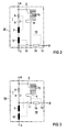
- the circuit breaker 1 is shown in FIGS Figure 1 in detail from an arc chamber with quenching plates 3 and rails 4, an associated switch 5, a thermal release 6 and a magnetic drive 7 formed.
- the dashed line always outputs that the integration of the circuit breaker 1 and the bridging device 10 common protective device formed on.
- the magnetic drive 12 Bridging device 10 de-energized and the switch 11 interrupts relatively early with its switching voltage the load current.
- the protective device differs from that of Figure 2 essentially by the arrangement the magnetic drives 7 and 12 in the load circuit instead of in the feed circuit.
- the magnetic drives 7 and 12 need this no longer designed for the full short-circuit load will.
- the arrangement according to FIG. 3 is therefore special advantageous because after the current relief of the switch 11 through the arc commutation into the switching chamber 2 whose switch-on contact remains closed as long as the magnetic excitation of the magnetic drives 7 and 12 by stops the load current.
- the switch 11 opens the switch-on contact therefore free of arcing after the decay of the Load current.
- connection C the connection point of the Bridging branch.
- the magnetic drives 7 and 12 can by a common magnetic drive for triggering and bridging are replaced.
- bypass circuit can be designed with multiple poles the individual connections are to be connected or connected to the neutral conductor. With an integrated Set up as a multi-pole bypass switch the connection of connections D in the device.
Landscapes
- Arc-Extinguishing Devices That Are Switches (AREA)
- Emergency Protection Circuit Devices (AREA)
Description
- Figur 1
- das Prinzip einer Überbrückungsschaltung zum Kurzschlußschutz empfindlicher Anlagenteile eines Lastkreises und die
- Figuren 2 und 3
- zwei erfindungsgemäße Möglichkeiten der Integration des Leistungsschalters und der Überbrückungsschaltung gemäß Figur 1 zu einer gemeinsamen Schutzeinrichtung.
Claims (10)
- Anordnung zur Freischaltung von Abzweigen eines Niederspannungs-Leitungsnetzes im Kurzschlußfall, bei dem im Abzweig Verbraucher (9) an Phasenleiter (L) und einen zugehörigen Nulleiter (N) geschaltet sind, wobei dem Verbraucher (9) ein Schaltelement (8) zum Ein- und/oder Ausschalten vorgeschaltet ist und im Phasenleiter (L) und/oder Nulleiter (N) zusätzliche Schaltelemente zur Kurzschlußabschaltung vorgesehen sind, an die eine Uberbrückungsschaltung (10) mit Schalter (11) angeschaltet ist, wobei nur im Phasenleiter (L) ein einziger Leistungsschalter (1) vorhanden ist, dadurch gekennzeichnet, daß auf der Lastseite des einzigen Leistungsschalters (1) die Überbrückungsschaltung (10) einen Teil des Kurzschlußstromes am Schalter (11) vorbeileitet, wobei in der Überbrückungsschaltung (10) ein Überbrückungsstromzweig (13) mit Widerstand (14) vorhanden ist, dessen Widerstandswert zwischen 25 und 50 % des Wertes der kleinsten zu erwartenden Lastkreisimpedanz beträgt und über den der magnetisch angetriebene Schalter (11) am Nullleiter (N) angeschlossen ist.
- Anordnung nach Anspruch 1, dadurch gekennzeichnet, daß die Überbrückungsschaltung (10) zusammen mit dem Leistungsschalter (1) eine Einheit (20) bildet.
- Anordnung nach Anspruch 2, dadurch gekennzeichnet, daß die beiden Magnetantriebe (7, 12) für den Leistungsschalter (1) einerseits und den Überbrückungsstromzweig (13) andererseits sich im Lastkreis befinden.
- Anordnung nach Anspruch 3, dadurch gekennzeichnet, daß für die Auslösung des Leistungsschalters (1) einerseits und für das Einschalten des Schalters (11) andererseits ein gemeinsamer Magnetantrieb vorhanden ist.
- Anordnung nach einem der vorhergehenden Ansprüche, mit einem thermischen Auslöser für den Leistungsschalter, dadurch gekennzeichnet, daß der thermische Auslöser (6) auf der Lastseite des überbrückungsstromzweiges (13) angeordnet ist.
- Anordnung nach Anspruch 2 und Anspruch 5, dadurch gekennzeichnet, daß der Überbrückungsstromzweig (13) mit dem Anschlußpunkt der Laufschiene (4) des Leistungsschalters (1) verbunden ist, so daß über die Lichtbogenkammer (2) des Leistungsschalters (1) der thermische und der magnetische Auslöser (6, 7) sowie oer Magnetantrieb (12) überbrückt werden.
- Anordnung nach einem der vorhergehenden Ansprüche, gekennzeichnet in der Anwendung als mehrpolige Überbrückungsschaltung bei mehrphasigen Netzen.
- Anordnung nach einem der vorhergehenden Ansprüche, gekennzeichnet durch die Verwendung von verschweißsicheren Kontaktwerkstoffen beim Einschaltkontakt des Schalters (11) der Überbrückungsschaltung (10).
- Anordnung nach Anspruch 8, dadurch gekennzeichnet, daß Kontaktwerkstoffe auf der Basis von Silber-Metalloxid (AgMeO), Silber-Graphit (AgC) oder Kupfer-Graphit (CuC) verwendet werden.
- Anordnung nach Anspruch 8 und Anspruch 9, gekennzeichnet durch eine unsymmetrische Kontaktpaarung.
Applications Claiming Priority (3)
| Application Number | Priority Date | Filing Date | Title |
|---|---|---|---|
| DE4309794 | 1993-03-25 | ||
| DE4309794A DE4309794A1 (de) | 1993-03-25 | 1993-03-25 | Anordnung zur Freischaltung von Abzweigen eines Niederspannungs-Leitungsnetzes im Kurzschlußfall |
| PCT/DE1994/000296 WO1994022197A1 (de) | 1993-03-25 | 1994-03-17 | Anordnung zur freischaltung von abzweigen eines niederspannungs-leitungsnetzes im kurzschlussfall |
Publications (2)
| Publication Number | Publication Date |
|---|---|
| EP0691046A1 EP0691046A1 (de) | 1996-01-10 |
| EP0691046B1 true EP0691046B1 (de) | 1998-01-21 |
Family
ID=6483886
Family Applications (1)
| Application Number | Title | Priority Date | Filing Date |
|---|---|---|---|
| EP94910342A Expired - Lifetime EP0691046B1 (de) | 1993-03-25 | 1994-03-17 | Anordnung zur freischaltung von abzweigen eines niederspannungs-leitungsnetzes im kurzschlussfall |
Country Status (5)
| Country | Link |
|---|---|
| US (1) | US5689397A (de) |
| EP (1) | EP0691046B1 (de) |
| JP (1) | JP3456996B2 (de) |
| DE (2) | DE4309794A1 (de) |
| WO (1) | WO1994022197A1 (de) |
Cited By (1)
| Publication number | Priority date | Publication date | Assignee | Title |
|---|---|---|---|---|
| DE19834474A1 (de) * | 1998-07-30 | 2000-02-10 | Siemens Ag | Einrichtung zum Kurzschlußschutz |
Families Citing this family (7)
| Publication number | Priority date | Publication date | Assignee | Title |
|---|---|---|---|---|
| DE19813952C1 (de) * | 1998-03-28 | 1999-11-04 | Telefunken Microelectron | Signalisierungsendstufe zur Erzeugung digitaler Spannungssignale auf einem Bussystem |
| US7408274B2 (en) * | 2004-12-30 | 2008-08-05 | Inpower Llc | Control and operating condition monitoring of dual series switch contactors for electric motor or other electrical load |
| FR2912253B1 (fr) * | 2007-02-01 | 2009-03-06 | Schneider Electric Ind Sas | Dispositif de protection contre les surtensions a contact mobile comprenant des moyens de deconnexions selectifs contre des courts-circuits |
| DE102008030987A1 (de) * | 2008-06-27 | 2010-01-07 | Siemens Aktiengesellschaft | Verfahren zum selektiven Auslösen von Leistungsschaltern im Falle eines Kurzschlusses |
| WO2011116832A1 (en) * | 2010-03-26 | 2011-09-29 | Abb Research Ltd | A hybrid circuit breaker |
| GB202018480D0 (en) * | 2020-11-24 | 2021-01-06 | Gridon Ltd | Fault current limiter-divrter (fcld) |
| KR20260023038A (ko) | 2023-07-25 | 2026-02-20 | 미쓰비시덴키 가부시키가이샤 | 전력 계통 보호 시스템 |
Family Cites Families (5)
| Publication number | Priority date | Publication date | Assignee | Title |
|---|---|---|---|---|
| US2924752A (en) * | 1957-07-12 | 1960-02-09 | Ite Circuit Breaker Ltd | Combined circuit breaker and short circuiter |
| DE2222517B2 (de) * | 1972-05-08 | 1972-12-21 | Josef Pfanzelt | Schaltvorrichtung in hybrid-technik zum lastfreien schalten von mit alternierender spannung gespeisten stromverbrauchern mit beliebigem phasenverschiebungswinkel |
| DE4040359C2 (de) * | 1990-12-17 | 1994-01-27 | Siemens Ag | Einrichtung zum Kurzschlußschutz |
| EP0504463B1 (de) * | 1991-03-21 | 1996-10-09 | Siemens Aktiengesellschaft | Schaltungsanordnung zur Stromversorgung |
| DE4110335C2 (de) * | 1991-03-28 | 1995-07-20 | Siemens Ag | Einrichtung zum Kurzschlußschutz |
-
1993
- 1993-03-25 DE DE4309794A patent/DE4309794A1/de not_active Withdrawn
-
1994
- 1994-03-17 WO PCT/DE1994/000296 patent/WO1994022197A1/de not_active Ceased
- 1994-03-17 EP EP94910342A patent/EP0691046B1/de not_active Expired - Lifetime
- 1994-03-17 DE DE59405117T patent/DE59405117D1/de not_active Expired - Fee Related
- 1994-03-17 US US08/525,676 patent/US5689397A/en not_active Expired - Fee Related
- 1994-03-17 JP JP52051794A patent/JP3456996B2/ja not_active Expired - Fee Related
Cited By (1)
| Publication number | Priority date | Publication date | Assignee | Title |
|---|---|---|---|---|
| DE19834474A1 (de) * | 1998-07-30 | 2000-02-10 | Siemens Ag | Einrichtung zum Kurzschlußschutz |
Also Published As
| Publication number | Publication date |
|---|---|
| JP3456996B2 (ja) | 2003-10-14 |
| JPH08508154A (ja) | 1996-08-27 |
| WO1994022197A1 (de) | 1994-09-29 |
| US5689397A (en) | 1997-11-18 |
| DE59405117D1 (de) | 1998-02-26 |
| EP0691046A1 (de) | 1996-01-10 |
| DE4309794A1 (de) | 1994-09-29 |
Similar Documents
| Publication | Publication Date | Title |
|---|---|---|
| EP2048679B1 (de) | Lasttrenner-Anordnung | |
| EP0691046B1 (de) | Anordnung zur freischaltung von abzweigen eines niederspannungs-leitungsnetzes im kurzschlussfall | |
| DE4335965A1 (de) | Motorstarter mit integriertem Kurzschlußschutz | |
| DE4110335C2 (de) | Einrichtung zum Kurzschlußschutz | |
| DE3431581A1 (de) | Elektrischer Schalter | |
| EP1685578A1 (de) | Sicherungsbehaftetes schaltschutzger t | |
| EP1101234B1 (de) | Einrichtung zum kurzschlussschutz | |
| EP3101678B1 (de) | Stromunterbrecher | |
| EP0343390B1 (de) | Motorstarter mit Kurzschlussschutz | |
| DE4023237A1 (de) | Schalteinrichtung mit einem lastschalter oder lasttrennschalter und einer sicherung | |
| EP3889986B1 (de) | Elektromechanisches kompakt-schutzschaltgerät | |
| EP0504463B1 (de) | Schaltungsanordnung zur Stromversorgung | |
| DE69734277T2 (de) | Nullstromkreisunterbrechung | |
| DE3133200A1 (de) | Leitungsschutzschalter, geeignet als vorautomat | |
| EP4213175B1 (de) | Niederspannungs-schutzschaltgerät mit einer leiterplatte und einem spannungsabgriff und montageverfahren | |
| DE2720736C2 (de) | Höchststrombegrenzer für eine elektrische Schaltanlage | |
| DE102022204329A1 (de) | Modulares Isolierstoffgehäuse und mehrpoliges modulares Reiheneinbaugerät | |
| AT413168B (de) | Fehlerstrom-schutzeinrichtung mit netzspannungsabhängiger fehlerstromauslösung und hohem eigenschaltvermögen | |
| DE102020211531A1 (de) | Niederspannungs-Schutzschaltgerät | |
| DE102023212542A1 (de) | Schutzschaltgerät | |
| WO2024046795A1 (de) | Schutzschaltgerät und verfahren | |
| EP0504464B1 (de) | Schalteinrichtung zur Unterbrechung eines Stromkreises | |
| DE254796C (de) | ||
| EP4548441A1 (de) | Schutzschaltgerät und verfahren | |
| DE1202863B (de) | Elektrischer Kurzschlussunterbrecher |
Legal Events
| Date | Code | Title | Description |
|---|---|---|---|
| PUAI | Public reference made under article 153(3) epc to a published international application that has entered the european phase |
Free format text: ORIGINAL CODE: 0009012 |
|
| 17P | Request for examination filed |
Effective date: 19950705 |
|
| AK | Designated contracting states |
Kind code of ref document: A1 Designated state(s): CH DE FR IT LI SE |
|
| 17Q | First examination report despatched |
Effective date: 19960711 |
|
| GRAG | Despatch of communication of intention to grant |
Free format text: ORIGINAL CODE: EPIDOS AGRA |
|
| GRAG | Despatch of communication of intention to grant |
Free format text: ORIGINAL CODE: EPIDOS AGRA |
|
| GRAH | Despatch of communication of intention to grant a patent |
Free format text: ORIGINAL CODE: EPIDOS IGRA |
|
| GRAH | Despatch of communication of intention to grant a patent |
Free format text: ORIGINAL CODE: EPIDOS IGRA |
|
| GRAA | (expected) grant |
Free format text: ORIGINAL CODE: 0009210 |
|
| AK | Designated contracting states |
Kind code of ref document: B1 Designated state(s): CH DE FR IT LI SE |
|
| REG | Reference to a national code |
Ref country code: CH Ref legal event code: NV Representative=s name: SIEMENS SCHWEIZ AG Ref country code: CH Ref legal event code: EP |
|
| REF | Corresponds to: |
Ref document number: 59405117 Country of ref document: DE Date of ref document: 19980226 |
|
| ET | Fr: translation filed | ||
| ITF | It: translation for a ep patent filed | ||
| PLBE | No opposition filed within time limit |
Free format text: ORIGINAL CODE: 0009261 |
|
| STAA | Information on the status of an ep patent application or granted ep patent |
Free format text: STATUS: NO OPPOSITION FILED WITHIN TIME LIMIT |
|
| 26N | No opposition filed | ||
| PGFP | Annual fee paid to national office [announced via postgrant information from national office to epo] |
Ref country code: SE Payment date: 20030318 Year of fee payment: 10 |
|
| PGFP | Annual fee paid to national office [announced via postgrant information from national office to epo] |
Ref country code: CH Payment date: 20030612 Year of fee payment: 10 |
|
| PG25 | Lapsed in a contracting state [announced via postgrant information from national office to epo] |
Ref country code: SE Free format text: LAPSE BECAUSE OF NON-PAYMENT OF DUE FEES Effective date: 20040318 |
|
| PG25 | Lapsed in a contracting state [announced via postgrant information from national office to epo] |
Ref country code: LI Free format text: LAPSE BECAUSE OF NON-PAYMENT OF DUE FEES Effective date: 20040331 Ref country code: CH Free format text: LAPSE BECAUSE OF NON-PAYMENT OF DUE FEES Effective date: 20040331 |
|
| EUG | Se: european patent has lapsed | ||
| REG | Reference to a national code |
Ref country code: CH Ref legal event code: PL |
|
| PG25 | Lapsed in a contracting state [announced via postgrant information from national office to epo] |
Ref country code: IT Free format text: LAPSE BECAUSE OF NON-PAYMENT OF DUE FEES;WARNING: LAPSES OF ITALIAN PATENTS WITH EFFECTIVE DATE BEFORE 2007 MAY HAVE OCCURRED AT ANY TIME BEFORE 2007. THE CORRECT EFFECTIVE DATE MAY BE DIFFERENT FROM THE ONE RECORDED. Effective date: 20050317 |
|
| PGFP | Annual fee paid to national office [announced via postgrant information from national office to epo] |
Ref country code: DE Payment date: 20070521 Year of fee payment: 14 |
|
| PGFP | Annual fee paid to national office [announced via postgrant information from national office to epo] |
Ref country code: FR Payment date: 20070320 Year of fee payment: 14 |
|
| REG | Reference to a national code |
Ref country code: FR Ref legal event code: ST Effective date: 20081125 |
|
| PG25 | Lapsed in a contracting state [announced via postgrant information from national office to epo] |
Ref country code: DE Free format text: LAPSE BECAUSE OF NON-PAYMENT OF DUE FEES Effective date: 20081001 |
|
| PG25 | Lapsed in a contracting state [announced via postgrant information from national office to epo] |
Ref country code: FR Free format text: LAPSE BECAUSE OF NON-PAYMENT OF DUE FEES Effective date: 20080331 |